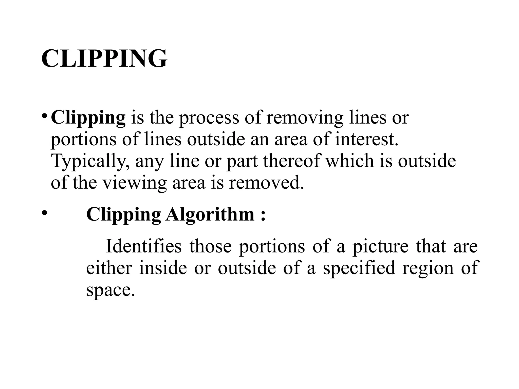
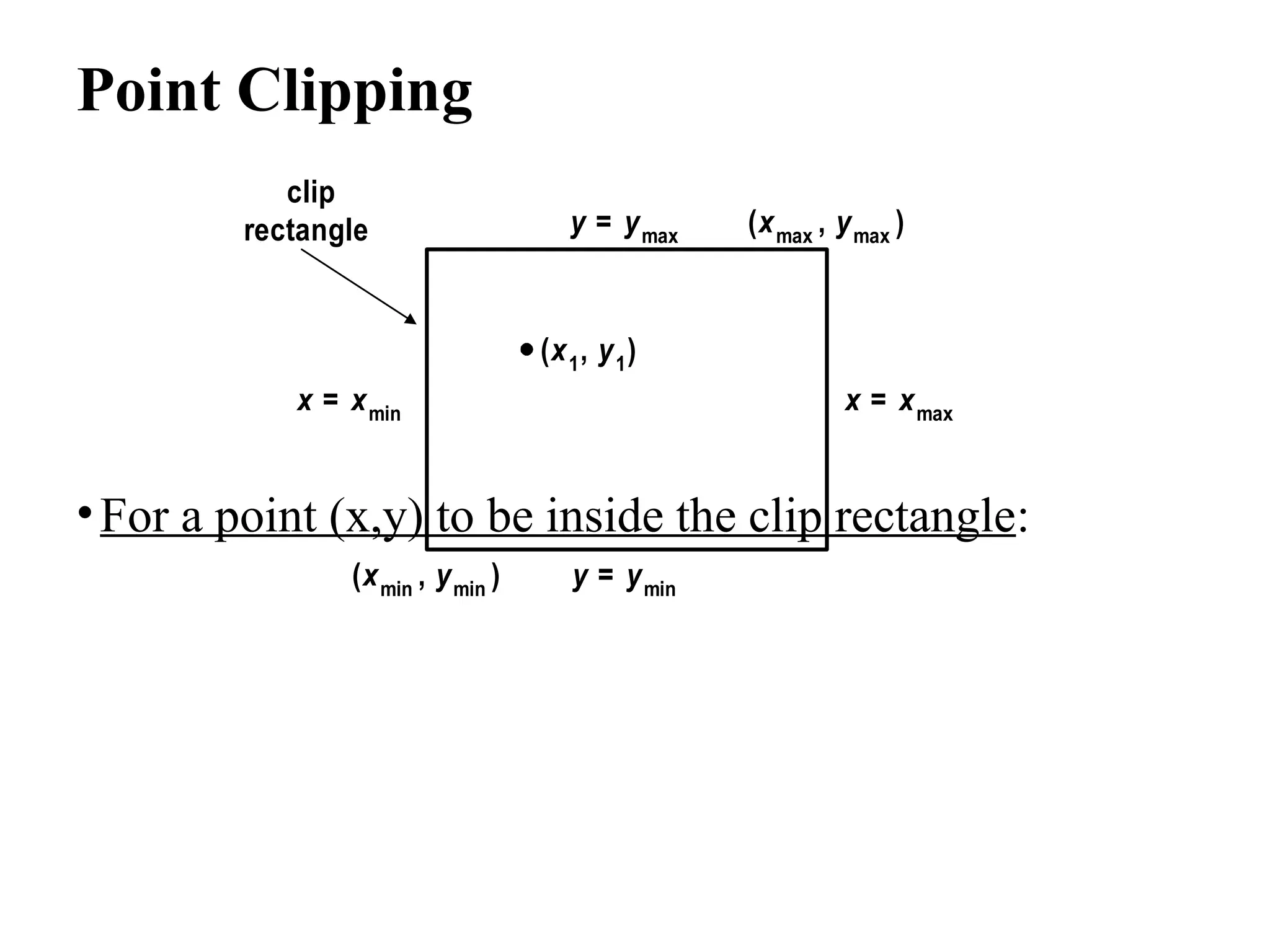
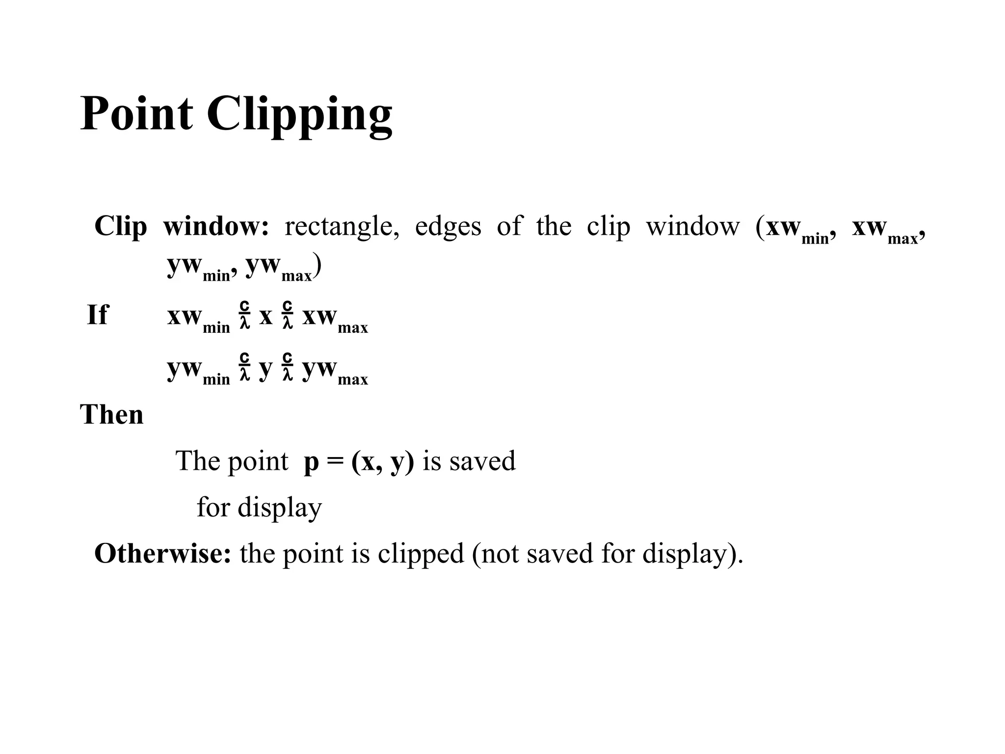
COMPUTER GRAPHICS
CLIPPING
CLIPPING
•Clipping is the process of removing lines or
portions of lines outside an area of interest.
Typically, any line or part thereof which is outside
of the viewing area is removed.
• Clipping Algorithm :
Identifies those portions of a picture that are
either inside or outside of a specified region of
space.
TYPES OF CLIPPING
-Point Clipping
-Line Clipping
-Area Clipping(polygon clipping)
-Curve Clipping
-Text Clipping
Point Clipping
•For a point (x,y) to be inside the clip rectangle:
(xmin , ymin )
(xmax , ymax )
x = xmin x = xmax
y = ymin
y = ymax
(x1, y1)
clip
rectangle
Point Clipping
Clip window: rectangle, edges of the clip window (xwmin
, xwmax
,
ywmin
, ywmax
)
If xwmin
 x  xwmax
ywmin
 y  ywmax
Then
The point p = (x, y) is saved
for display
Otherwise: the point is clipped (not saved for display).
Line Clipping
Before clipping After clipping
Line clipping against a rectangular window
Line Clipping
Inside – Outside test:
• Completely Inside: A line with both endpoints inside
all clipping boundaries, such as the line from p1
to p2
,
is saved.
•Completely Outside: A line with both endpoints
outside any one of the clip boundaries, such as the line
from p3
to p4
, is not saved.
•If the line is not completely inside or completely
outside, we must perform intersection calculations
with one or more clipping boundaries.
Cohen-Sutherland Line Clipping
•This method speeds up the processing of the line
segment by performing initial tests that reduce the
number of intersections that must be calculated.
• Every line endpoint in a picture is assigned a four-
digit binary code, called region code that identifies
the location of the point relative to the boundaries of
the clipping rectangle.
Bit 4 Bit 3 Bit 2 Bit 1
Above Below Right Left
Cohen-Sutherland Line Clipping
1001 1000 1010
0001
Window
0000 0010
0101 0100 0110
Bit 4 Bit 3 Bit 2 Bit 1
Above Below Right Left
Cohen-Sutherland Line Clipping
Region-code bit values can be determined
as follows:
Bit 1 is the sign bit of x – xwmin
Bit 2 is the sign bit of xwmax – x
Bit 3 is the sign bit of y – ywmin
Bit 4 is the sign bit of ywmax – y
If the sign is negative the bit is set to 1
otherwise is set to 0.
Cohen-Sutherland Line Clipping
•Any lines that has a region code of 0000 for both
endpoint are completely inside, we save these lines.
• Any lines that have a 1 in the same bit position in
the region-codes for each endpoint are completely
outside and we reject these lines.
• A method that can be used to test lines for total
clipping is to perform the logical AND operation
with both region codes. If the result is not 0000, the
line is completely outside the clipping region.
Cohen-Sutherland Line Clipping
• p1 0100
• p2 1001
• p3 0001
• p4 0100
•p1 AND p2 =0000
•p3 AND p4 =0000
Bit 4 Bit 3 Bit 2 Bit 1
Above Below Right Left
Cohen-Sutherland Line Clipping
• For a line with endpoint (x1
, y1
) and (x2
, y2
)
m = (y2
– y1
) / (x2
– x1
)
• Intersection points with the clipping boundary:
• The intersection with vertical boundary (x=xwmin
or x=xwmax
), the y
coordinate can be calculated as:
y = y1
+ m(x – x1
)
• The intersection with a horizontal boundary (y=ywmin
or y=ywmax.
),
the x coordinate can be calculated as
x = x1
+ (y – y1
) / m
Liang-Barsky Line Clipping
Algorithm
1. For each line, calculate the parameters p, q and r:
• p1
= – x, q1
= x1
– xwmin
, r1
= q1
/ p1
• p2
= x, q2
= xwmax
– x1
, r2
= q2
/ p2
• p3
= – y, q3
= y1
– ywmin
, r3
= q3
/ p3
• p4
= y, q4
= ywmax
– y1
, r1
= q4
/ p4
Liang-Barsky Line Clipping
Algorithm
2. Determine the value of u1
is by looking at the
rectangle edges for which the line proceeds from
outside to the inside (pk
< 0). The value of u1
is
taken as the largest of the set consisting of 0 and
the various values of r.
3. Determine the value of u2
by examining the
boundaries for which the line proceeds from
inside to the outside (pk
> 0). A value of rk
is
calculated for each of these boundaries, and the
value of u2
is the minimum of the set consisting
of 1 and the calculated r values.
Liang-Barsky Line Clipping Algorithm
4. If u1
> u2
, the line is completely outside the clip
window and it can be discarded.
5.Otherwise, the endpoints of the clipped line are
calculated from the two values of parameter u.
• If u2
<1 x= x1
+u2
x, y = y1
+u2
y
• Otherwise x = x2
, y = y2
• If u1
>0 x= x1
+u1
x, y = y1
+u1
dy
• Otherwise x = x1
, y = y1
Area Clipping (polygon clipping)
To clip a polygon, we cannot directly apply a line-
clipping method to the individual polygon edges
because this approach would produce a series of
unconnected line segments as shown in figure .
Area Clipping (polygon clipping)
• The clipped polygons must be a bounded area after clipping
as shown in figure.
• For polygon clipping, we require an algorithm that will
generate one or more closed areas that are then scan
converted for the appreciate area fill.
• The output of a polygon clipper should be a sequence of
vertices that defines the clipped polygon boundaries.
Sutherland-Hodgman Polygon
Clipping
• Clip a polygon by processing the polygon boundary as a
whole against each window edge.
• Processing all polygon vertices against each clip rectangle
boundary in turn.
• Beginning with the initial set of polygon vertices, we could
first clip the polygon against the left rectangle boundary to
produce a new sequence of vertices
• The new set of vertices could be successively passed to a
right boundary clipper, a bottom boundary clipper, and a
top boundary clipper, a right boundary clipper.
Sutherland-Hodgman Polygon
Clipping
There are four possible cases when processing
vertices in sequence around the perimeter of a
polygon.
As each pair of adjacent polygon vertices is passed
to a next window boundary clipper, we make the
following tests:
Sutherland-Hodgman Polygon
Clipping
1. If the first vertex is outside the window boundary
and the second vertex is inside
• Then , both the intersection point of the polygon
edge with the window boundary and the second
vertex are added to the output vertex list.
Sutherland-Hodgman Polygon
Clipping
2. If both input vertices are inside the window
boundary.
• Then, only the second vertex is added to the
output vertex list.
Sutherland-Hodgman Polygon
Clipping
3. If the first vertex is inside the window boundary
and the second vertex is outside.
• Then, only the edge intersection with the window
boundary is added to the output vertex list.
Sutherland-Hodgman Polygon
Clipping
4. If both input vertices are outside the window
boundary.
• Then, nothing is added to the output vertex list.
Curve Clipping
•Curve clipping procedures will
involve non-linear equations.
•So requires more processing
than for objects with linear
Boundaries.
Text Clipping
•There are several techniques that can be used to
provide text clipping in a graphics packages.
•The choice of clipping method depends on how
characters are generated and what requirements
we have for displaying character strings.
Text Clipping
•All-or-none string-clipping
• If all of the string is inside a clip window, we keep
it.
•Otherwise the string is discarded.
Text Clipping
•All-or-none character-clipping
•Here we discard only those characters that are not
completely inside the window
Text Clipping
•Clip the components of individual characters
•We treat characters in much the same way that we
treated lines.
•If an individual character overlaps a clip window
boundary, we clip off the parts of the character that are
outside the window

clippiNG COMPUTER GRAPHICS A NEW ERA.pptx

  • 1.
  • 2.
    CLIPPING •Clipping is theprocess of removing lines or portions of lines outside an area of interest. Typically, any line or part thereof which is outside of the viewing area is removed. • Clipping Algorithm : Identifies those portions of a picture that are either inside or outside of a specified region of space.
  • 3.
    TYPES OF CLIPPING -PointClipping -Line Clipping -Area Clipping(polygon clipping) -Curve Clipping -Text Clipping
  • 4.
    Point Clipping •For apoint (x,y) to be inside the clip rectangle: (xmin , ymin ) (xmax , ymax ) x = xmin x = xmax y = ymin y = ymax (x1, y1) clip rectangle
  • 5.
    Point Clipping Clip window:rectangle, edges of the clip window (xwmin , xwmax , ywmin , ywmax ) If xwmin  x  xwmax ywmin  y  ywmax Then The point p = (x, y) is saved for display Otherwise: the point is clipped (not saved for display).
  • 6.
    Line Clipping Before clippingAfter clipping Line clipping against a rectangular window
  • 7.
    Line Clipping Inside –Outside test: • Completely Inside: A line with both endpoints inside all clipping boundaries, such as the line from p1 to p2 , is saved. •Completely Outside: A line with both endpoints outside any one of the clip boundaries, such as the line from p3 to p4 , is not saved. •If the line is not completely inside or completely outside, we must perform intersection calculations with one or more clipping boundaries.
  • 8.
    Cohen-Sutherland Line Clipping •Thismethod speeds up the processing of the line segment by performing initial tests that reduce the number of intersections that must be calculated. • Every line endpoint in a picture is assigned a four- digit binary code, called region code that identifies the location of the point relative to the boundaries of the clipping rectangle. Bit 4 Bit 3 Bit 2 Bit 1 Above Below Right Left
  • 9.
    Cohen-Sutherland Line Clipping 10011000 1010 0001 Window 0000 0010 0101 0100 0110 Bit 4 Bit 3 Bit 2 Bit 1 Above Below Right Left
  • 10.
    Cohen-Sutherland Line Clipping Region-codebit values can be determined as follows: Bit 1 is the sign bit of x – xwmin Bit 2 is the sign bit of xwmax – x Bit 3 is the sign bit of y – ywmin Bit 4 is the sign bit of ywmax – y If the sign is negative the bit is set to 1 otherwise is set to 0.
  • 11.
    Cohen-Sutherland Line Clipping •Anylines that has a region code of 0000 for both endpoint are completely inside, we save these lines. • Any lines that have a 1 in the same bit position in the region-codes for each endpoint are completely outside and we reject these lines. • A method that can be used to test lines for total clipping is to perform the logical AND operation with both region codes. If the result is not 0000, the line is completely outside the clipping region.
  • 12.
    Cohen-Sutherland Line Clipping •p1 0100 • p2 1001 • p3 0001 • p4 0100 •p1 AND p2 =0000 •p3 AND p4 =0000 Bit 4 Bit 3 Bit 2 Bit 1 Above Below Right Left
  • 13.
    Cohen-Sutherland Line Clipping •For a line with endpoint (x1 , y1 ) and (x2 , y2 ) m = (y2 – y1 ) / (x2 – x1 ) • Intersection points with the clipping boundary: • The intersection with vertical boundary (x=xwmin or x=xwmax ), the y coordinate can be calculated as: y = y1 + m(x – x1 ) • The intersection with a horizontal boundary (y=ywmin or y=ywmax. ), the x coordinate can be calculated as x = x1 + (y – y1 ) / m
  • 14.
    Liang-Barsky Line Clipping Algorithm 1.For each line, calculate the parameters p, q and r: • p1 = – x, q1 = x1 – xwmin , r1 = q1 / p1 • p2 = x, q2 = xwmax – x1 , r2 = q2 / p2 • p3 = – y, q3 = y1 – ywmin , r3 = q3 / p3 • p4 = y, q4 = ywmax – y1 , r1 = q4 / p4
  • 15.
    Liang-Barsky Line Clipping Algorithm 2.Determine the value of u1 is by looking at the rectangle edges for which the line proceeds from outside to the inside (pk < 0). The value of u1 is taken as the largest of the set consisting of 0 and the various values of r. 3. Determine the value of u2 by examining the boundaries for which the line proceeds from inside to the outside (pk > 0). A value of rk is calculated for each of these boundaries, and the value of u2 is the minimum of the set consisting of 1 and the calculated r values.
  • 16.
    Liang-Barsky Line ClippingAlgorithm 4. If u1 > u2 , the line is completely outside the clip window and it can be discarded. 5.Otherwise, the endpoints of the clipped line are calculated from the two values of parameter u. • If u2 <1 x= x1 +u2 x, y = y1 +u2 y • Otherwise x = x2 , y = y2 • If u1 >0 x= x1 +u1 x, y = y1 +u1 dy • Otherwise x = x1 , y = y1
  • 17.
    Area Clipping (polygonclipping) To clip a polygon, we cannot directly apply a line- clipping method to the individual polygon edges because this approach would produce a series of unconnected line segments as shown in figure .
  • 18.
    Area Clipping (polygonclipping) • The clipped polygons must be a bounded area after clipping as shown in figure. • For polygon clipping, we require an algorithm that will generate one or more closed areas that are then scan converted for the appreciate area fill. • The output of a polygon clipper should be a sequence of vertices that defines the clipped polygon boundaries.
  • 20.
    Sutherland-Hodgman Polygon Clipping • Clipa polygon by processing the polygon boundary as a whole against each window edge. • Processing all polygon vertices against each clip rectangle boundary in turn. • Beginning with the initial set of polygon vertices, we could first clip the polygon against the left rectangle boundary to produce a new sequence of vertices • The new set of vertices could be successively passed to a right boundary clipper, a bottom boundary clipper, and a top boundary clipper, a right boundary clipper.
  • 21.
    Sutherland-Hodgman Polygon Clipping There arefour possible cases when processing vertices in sequence around the perimeter of a polygon. As each pair of adjacent polygon vertices is passed to a next window boundary clipper, we make the following tests:
  • 22.
    Sutherland-Hodgman Polygon Clipping 1. Ifthe first vertex is outside the window boundary and the second vertex is inside • Then , both the intersection point of the polygon edge with the window boundary and the second vertex are added to the output vertex list.
  • 23.
    Sutherland-Hodgman Polygon Clipping 2. Ifboth input vertices are inside the window boundary. • Then, only the second vertex is added to the output vertex list.
  • 24.
    Sutherland-Hodgman Polygon Clipping 3. Ifthe first vertex is inside the window boundary and the second vertex is outside. • Then, only the edge intersection with the window boundary is added to the output vertex list.
  • 25.
    Sutherland-Hodgman Polygon Clipping 4. Ifboth input vertices are outside the window boundary. • Then, nothing is added to the output vertex list.
  • 26.
    Curve Clipping •Curve clippingprocedures will involve non-linear equations. •So requires more processing than for objects with linear Boundaries.
  • 27.
    Text Clipping •There areseveral techniques that can be used to provide text clipping in a graphics packages. •The choice of clipping method depends on how characters are generated and what requirements we have for displaying character strings.
  • 28.
    Text Clipping •All-or-none string-clipping •If all of the string is inside a clip window, we keep it. •Otherwise the string is discarded.
  • 29.
    Text Clipping •All-or-none character-clipping •Herewe discard only those characters that are not completely inside the window
  • 30.
    Text Clipping •Clip thecomponents of individual characters •We treat characters in much the same way that we treated lines. •If an individual character overlaps a clip window boundary, we clip off the parts of the character that are outside the window