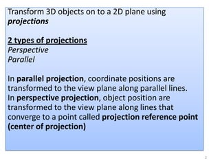
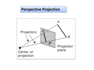
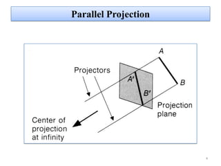
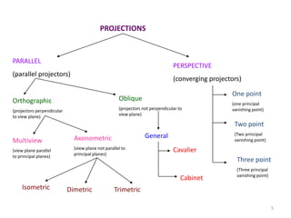
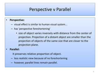
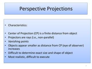
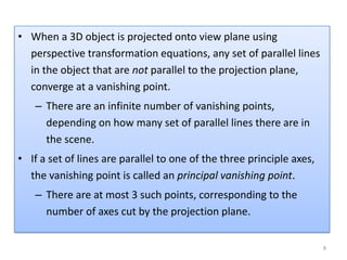
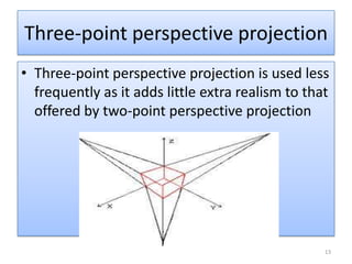
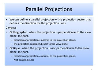
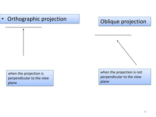
PROJECTIONS
Sanu Philip
No:47
1
Transform 3D objects on to a 2D plane using
projections
2 types of projections
Perspective
Parallel
In parallel projection, coordinate positions are
transformed to the view plane along parallel lines.
In perspective projection, object position are
transformed to the view plane along lines that
converge to a point called projection reference point
(center of projection)
2
Perspective Projection
3
Parallel Projection
4
PROJECTIONS
PARALLEL
(parallel projectors)
PERSPECTIVE
(converging projectors)
One point
(one principal
vanishing point)
Two point
(Two principal
vanishing point)
Three point
(Three principal
vanishing point)
Orthographic
(projectors perpendicular
to view plane)
Oblique
(projectors not perpendicular to
view plane)
General
Cavalier
Cabinet
Multiview
(view plane parallel
to principal planes)
Axonometric
(view plane not parallel to
principal planes)
Isometric Dimetric Trimetric
5
• Perspective:
– visual effect is similar to human visual system...
– has 'perspective foreshortening'
• size of object varies inversely with distance from the center of
projection. Projection of a distant object are smaller than the
projection of objects of the same size that are closer to the
projection plane.
• Parallel:
It preserves relative proportion of object.
– less realistic view because of no foreshortening
– however, parallel lines remain parallel.
Perspective v Parallel
6
Perspective Projections
• Characteristics:
• Center of Projection (CP) is a finite distance from object
• Projectors are rays (i.e., non-parallel)
• Vanishing points
• Objects appear smaller as distance from CP (eye of observer)
increases
• Difficult to determine exact size and shape of object
• Most realistic, difficult to execute
7
• When a 3D object is projected onto view plane using
perspective transformation equations, any set of parallel lines
in the object that are not parallel to the projection plane,
converge at a vanishing point.
– There are an infinite number of vanishing points,
depending on how many set of parallel lines there are in
the scene.
• If a set of lines are parallel to one of the three principle axes,
the vanishing point is called an principal vanishing point.
– There are at most 3 such points, corresponding to the
number of axes cut by the projection plane.
8
• Certain set of parallel lines appear to meet at a different point
– The Vanishing point for this direction
• Principal vanishing points are formed by the apparent
intersection of lines parallel to one of the three principal x, y, z
axes.
• The number of principal vanishing points is determined by the
number of principal axes intersected by the view plane.
• Sets of parallel lines on the same plane lead to collinear
vanishing points.
– The line is called the horizon for that plane
Vanishing points
9
Classes of Perspective Projection
• One-Point Perspective
• Two-Point Perspective
• Three-Point Perspective
10
One-Point Perspective
11
Two-point perspective projection:
– This is often used in architectural, engineering and
industrial design drawings.
–
12
Three-point perspective projection
• Three-point perspective projection is used less
frequently as it adds little extra realism to that
offered by two-point perspective projection
13
• We can define a parallel projection with a projection vector that
defines the direction for the projection lines.
2 types:
• Orthographic : when the projection is perpendicular to the view
plane. In short,
– direction of projection = normal to the projection plane.
– the projection is perpendicular to the view plane.
• Oblique : when the projection is not perpendicular to the view
plane. In short,
– direction of projection normal to the projection plane.
– Not perpendicular.
Parallel Projections
14
when the projection is
perpendicular to the view
plane
when the projection is not
perpendicular to the view
plane
• Orthographic projection Oblique projection
15
– Front, side and rear orthographic projection of an object are
called elevations and the top orthographic projection is called
plan view.
– all have projection plane perpendicular to a principle axes.
– Here length and angles are accurately depicted and measured
from the drawing, so engineering and architectural drawings
commonly employee this.
• However, As only one face of an object is shown, it can be hard to
create a mental image of the object, even when several views are
available.
Orthographic (or orthogonal) projections:
16
Orthogonal projections:
17
Axonometric orthographic projections
• Orthographic projections that show more than one face of an
object are called axonometric orthographic projections.
•
 The most common axonometric
projection is an isometric
projection where the projection
plane intersects each coordinate
axis in the model coordinate
system at an equal distance.
18
Cavalier projection:
All lines perpendicular to the projection plane are projected with
no change in length.
• 2 common oblique parallel projections:
Cavalier and Cabinet
19
Cabinet projection:
– Lines which are perpendicular to the projection plane
(viewing surface) are projected at 1 / 2 the length .
– This results in foreshortening of the z axis, and
provides a more “realistic” view.
20
THANK YOU
21

ppt.pdf

  • 1.
  • 2.
    Transform 3D objectson to a 2D plane using projections 2 types of projections Perspective Parallel In parallel projection, coordinate positions are transformed to the view plane along parallel lines. In perspective projection, object position are transformed to the view plane along lines that converge to a point called projection reference point (center of projection) 2
  • 3.
  • 4.
  • 5.
    PROJECTIONS PARALLEL (parallel projectors) PERSPECTIVE (converging projectors) Onepoint (one principal vanishing point) Two point (Two principal vanishing point) Three point (Three principal vanishing point) Orthographic (projectors perpendicular to view plane) Oblique (projectors not perpendicular to view plane) General Cavalier Cabinet Multiview (view plane parallel to principal planes) Axonometric (view plane not parallel to principal planes) Isometric Dimetric Trimetric 5
  • 6.
    • Perspective: – visualeffect is similar to human visual system... – has 'perspective foreshortening' • size of object varies inversely with distance from the center of projection. Projection of a distant object are smaller than the projection of objects of the same size that are closer to the projection plane. • Parallel: It preserves relative proportion of object. – less realistic view because of no foreshortening – however, parallel lines remain parallel. Perspective v Parallel 6
  • 7.
    Perspective Projections • Characteristics: •Center of Projection (CP) is a finite distance from object • Projectors are rays (i.e., non-parallel) • Vanishing points • Objects appear smaller as distance from CP (eye of observer) increases • Difficult to determine exact size and shape of object • Most realistic, difficult to execute 7
  • 8.
    • When a3D object is projected onto view plane using perspective transformation equations, any set of parallel lines in the object that are not parallel to the projection plane, converge at a vanishing point. – There are an infinite number of vanishing points, depending on how many set of parallel lines there are in the scene. • If a set of lines are parallel to one of the three principle axes, the vanishing point is called an principal vanishing point. – There are at most 3 such points, corresponding to the number of axes cut by the projection plane. 8
  • 9.
    • Certain setof parallel lines appear to meet at a different point – The Vanishing point for this direction • Principal vanishing points are formed by the apparent intersection of lines parallel to one of the three principal x, y, z axes. • The number of principal vanishing points is determined by the number of principal axes intersected by the view plane. • Sets of parallel lines on the same plane lead to collinear vanishing points. – The line is called the horizon for that plane Vanishing points 9
  • 10.
    Classes of PerspectiveProjection • One-Point Perspective • Two-Point Perspective • Three-Point Perspective 10
  • 11.
  • 12.
    Two-point perspective projection: –This is often used in architectural, engineering and industrial design drawings. – 12
  • 13.
    Three-point perspective projection •Three-point perspective projection is used less frequently as it adds little extra realism to that offered by two-point perspective projection 13
  • 14.
    • We candefine a parallel projection with a projection vector that defines the direction for the projection lines. 2 types: • Orthographic : when the projection is perpendicular to the view plane. In short, – direction of projection = normal to the projection plane. – the projection is perpendicular to the view plane. • Oblique : when the projection is not perpendicular to the view plane. In short, – direction of projection normal to the projection plane. – Not perpendicular. Parallel Projections 14
  • 15.
    when the projectionis perpendicular to the view plane when the projection is not perpendicular to the view plane • Orthographic projection Oblique projection 15
  • 16.
    – Front, sideand rear orthographic projection of an object are called elevations and the top orthographic projection is called plan view. – all have projection plane perpendicular to a principle axes. – Here length and angles are accurately depicted and measured from the drawing, so engineering and architectural drawings commonly employee this. • However, As only one face of an object is shown, it can be hard to create a mental image of the object, even when several views are available. Orthographic (or orthogonal) projections: 16
  • 17.
  • 18.
    Axonometric orthographic projections •Orthographic projections that show more than one face of an object are called axonometric orthographic projections. •  The most common axonometric projection is an isometric projection where the projection plane intersects each coordinate axis in the model coordinate system at an equal distance. 18
  • 19.
    Cavalier projection: All linesperpendicular to the projection plane are projected with no change in length. • 2 common oblique parallel projections: Cavalier and Cabinet 19
  • 20.
    Cabinet projection: – Lineswhich are perpendicular to the projection plane (viewing surface) are projected at 1 / 2 the length . – This results in foreshortening of the z axis, and provides a more “realistic” view. 20
  • 21.