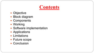
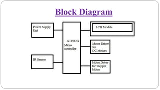
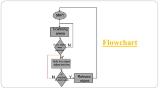
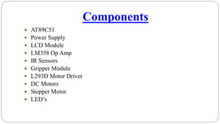
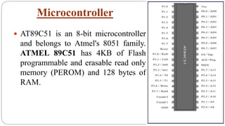
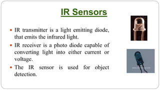
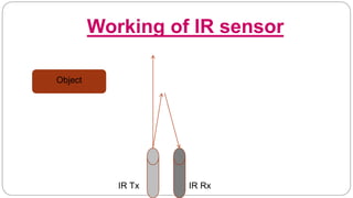
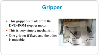
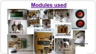
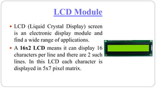
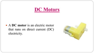
By
A. prem kumar
Autonomous Pick & Place
Robot
Contents
 Objective
 Block diagram
 Components
 Working
 Software implementation
 Applications
 Limitations
 Future scope
 Conclusion
Objective
 The main objective of this project is to built a
autonomous robot that can scan the specified arena
and picks the objects and place them in a specific
place with out human interference.
What is Autonomous Robot?
 Autonomous robots are robots that can perform
desired tasks in unstructured environments without
continuous human guidance.
Block Diagram
Flowchart
Y
If any object
was
detected
Hold the object
follow the line
Release
object
Y
N
N
start
Scanning
arena
IF
reached
to destination
Components
 AT89C51
 Power Supply
 LCD Module
 LM358 Op Amp
 IR Sensors
 Gripper Module
 L293D Motor Driver
 DC Motors
 Stepper Motor
 LED’s
Microcontroller
 AT89C51 is an 8-bit microcontroller
and belongs to Atmel's 8051 family.
ATMEL 89C51 has 4KB of Flash
programmable and erasable read only
memory (PEROM) and 128 bytes of
RAM.
IR Sensors
 IR transmitter is a light emitting diode,
that emits the infrared light.
 IR receiver is a photo diode capable of
converting light into either current or
voltage.
 The IR sensor is used for object
detection.
Working of IR sensor
Object
IR Tx IR Rx
Gripper
 This gripper is made from the
DVD-ROM stepper motor.
 This is very simple mechanism.
 One gripper if fixed and the other
is movable.
Modules used
LCD MODULE
DC MOTORS
ASSEMBLED ROBOT
8051 MAIN BOARD
MOTOR DRIVERS
TACTILE SWITCH
WHEELS
GRIPPER
IR SENSORS
CASTOR WHEEL
Power Supply
 Work based on 5V regulated supply.
 Supply is given through 12V DC rechargeable battery.
 Contain rechargeable circuit also.
LCD Module
 LCD (Liquid Crystal Display) screen
is an electronic display module and
find a wide range of applications.
 A 16x2 LCD means it can display 16
characters per line and there are 2 such
lines. In this LCD each character is
displayed in 5x7 pixel matrix.
DC Motors
 A DC motor is an electric motor
that runs on direct current (DC)
electricity.
Stepper Motor
 A stepper motor is an electromechanical device which
converts electrical pulses into discrete mechanical
movements.
Motor Driver
 L293D is a dual H-bridge motor driver
integrated circuit (IC).
 L293D contains two inbuilt H-bridge
driver circuits.
Working
 When it start’s it will scan for objects in the arena, if any
objects were found, it will pick it and follows the line until
it reaches it’s destination, then it will release the object at
destination and again goes into arena for scanning.
Software Implementation
 The Keil software is a user-friendly software suite
to develop the ‘C’ code and test the same in a virtual
8051 environment.
Applications
 This is applicable in the areas where the human
involvement is not required.
Limitations
 As it cannot sense the type of object it will try to pick
any object present in the fixed environment.
 It will scan for the objects even there are no objects
present in specific environment.
Future Scope
 Our project can be further extended by adding the color
sensor or a camera to sense the color and type of the
object to be handled. With this the accuracy to pick the
particular object in the arena will be increased.
Conclusion
 The development of this autonomous robots are very fast
now-a-days, so many new autonomous robots in different
fields were made.

Robotics

  • 1.
    By A. prem kumar AutonomousPick & Place Robot
  • 2.
    Contents  Objective  Blockdiagram  Components  Working  Software implementation  Applications  Limitations  Future scope  Conclusion
  • 3.
    Objective  The mainobjective of this project is to built a autonomous robot that can scan the specified arena and picks the objects and place them in a specific place with out human interference.
  • 4.
    What is AutonomousRobot?  Autonomous robots are robots that can perform desired tasks in unstructured environments without continuous human guidance.
  • 5.
  • 6.
    Flowchart Y If any object was detected Holdthe object follow the line Release object Y N N start Scanning arena IF reached to destination
  • 7.
    Components  AT89C51  PowerSupply  LCD Module  LM358 Op Amp  IR Sensors  Gripper Module  L293D Motor Driver  DC Motors  Stepper Motor  LED’s
  • 8.
    Microcontroller  AT89C51 isan 8-bit microcontroller and belongs to Atmel's 8051 family. ATMEL 89C51 has 4KB of Flash programmable and erasable read only memory (PEROM) and 128 bytes of RAM.
  • 9.
    IR Sensors  IRtransmitter is a light emitting diode, that emits the infrared light.  IR receiver is a photo diode capable of converting light into either current or voltage.  The IR sensor is used for object detection.
  • 10.
    Working of IRsensor Object IR Tx IR Rx
  • 11.
    Gripper  This gripperis made from the DVD-ROM stepper motor.  This is very simple mechanism.  One gripper if fixed and the other is movable.
  • 12.
    Modules used LCD MODULE DCMOTORS ASSEMBLED ROBOT 8051 MAIN BOARD MOTOR DRIVERS TACTILE SWITCH WHEELS GRIPPER IR SENSORS CASTOR WHEEL
  • 13.
    Power Supply  Workbased on 5V regulated supply.  Supply is given through 12V DC rechargeable battery.  Contain rechargeable circuit also.
  • 14.
    LCD Module  LCD(Liquid Crystal Display) screen is an electronic display module and find a wide range of applications.  A 16x2 LCD means it can display 16 characters per line and there are 2 such lines. In this LCD each character is displayed in 5x7 pixel matrix.
  • 15.
    DC Motors  ADC motor is an electric motor that runs on direct current (DC) electricity.
  • 16.
    Stepper Motor  Astepper motor is an electromechanical device which converts electrical pulses into discrete mechanical movements.
  • 17.
    Motor Driver  L293Dis a dual H-bridge motor driver integrated circuit (IC).  L293D contains two inbuilt H-bridge driver circuits.
  • 18.
    Working  When itstart’s it will scan for objects in the arena, if any objects were found, it will pick it and follows the line until it reaches it’s destination, then it will release the object at destination and again goes into arena for scanning.
  • 19.
    Software Implementation  TheKeil software is a user-friendly software suite to develop the ‘C’ code and test the same in a virtual 8051 environment.
  • 20.
    Applications  This isapplicable in the areas where the human involvement is not required.
  • 21.
    Limitations  As itcannot sense the type of object it will try to pick any object present in the fixed environment.  It will scan for the objects even there are no objects present in specific environment.
  • 22.
    Future Scope  Ourproject can be further extended by adding the color sensor or a camera to sense the color and type of the object to be handled. With this the accuracy to pick the particular object in the arena will be increased.
  • 23.
    Conclusion  The developmentof this autonomous robots are very fast now-a-days, so many new autonomous robots in different fields were made.