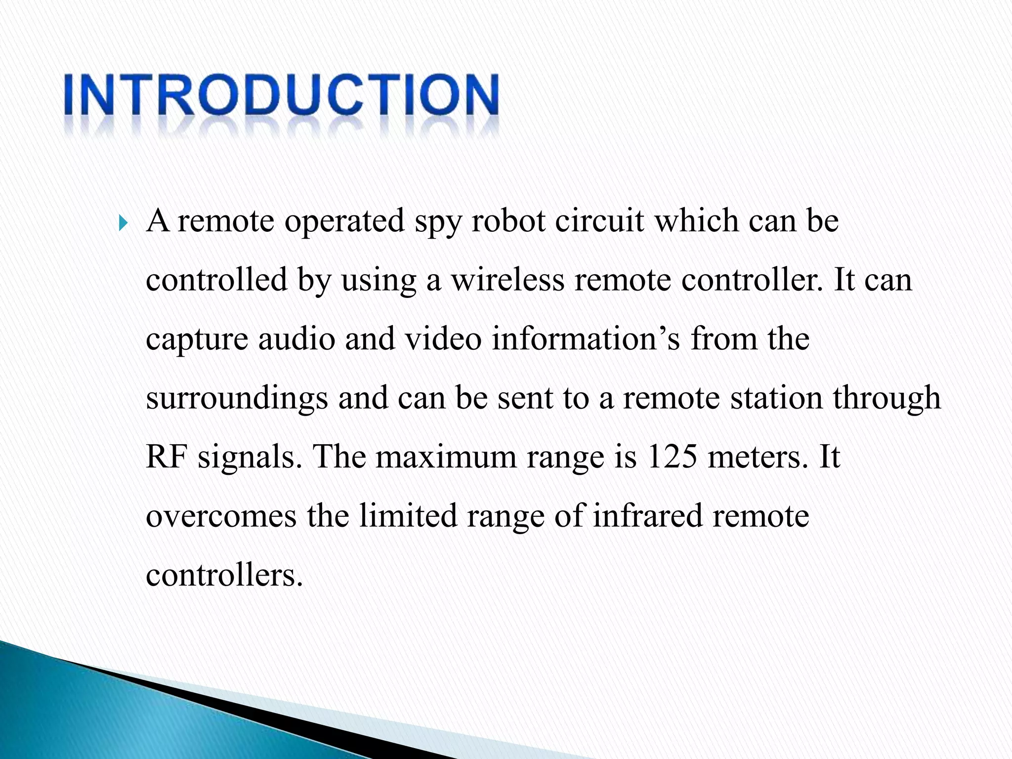
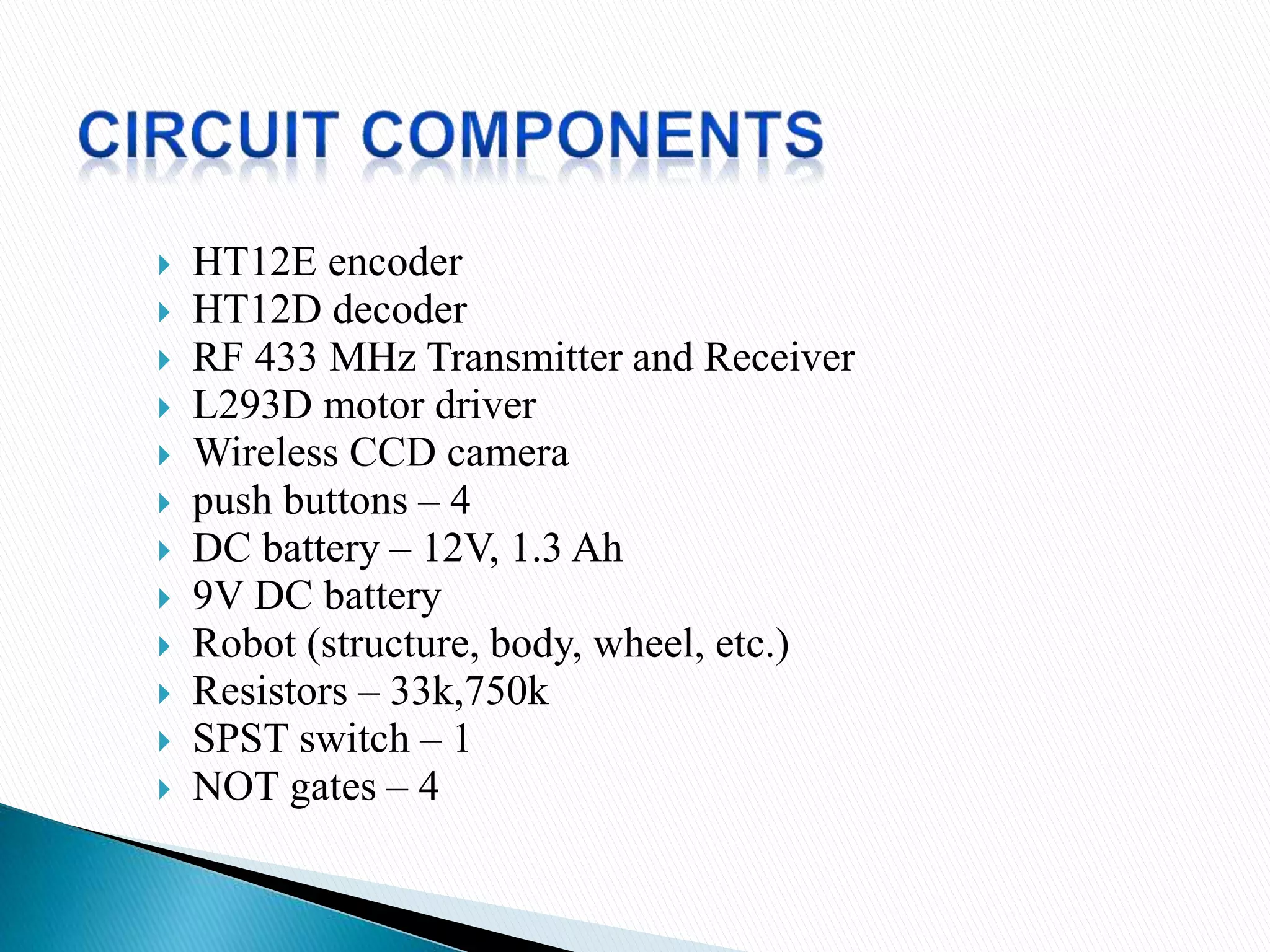
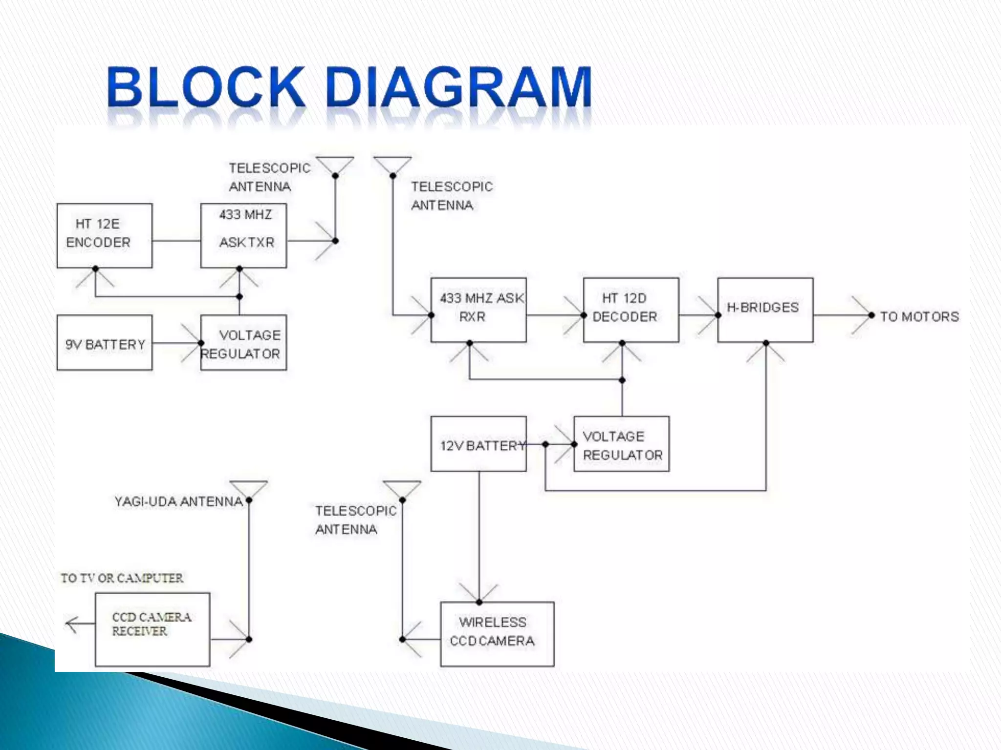
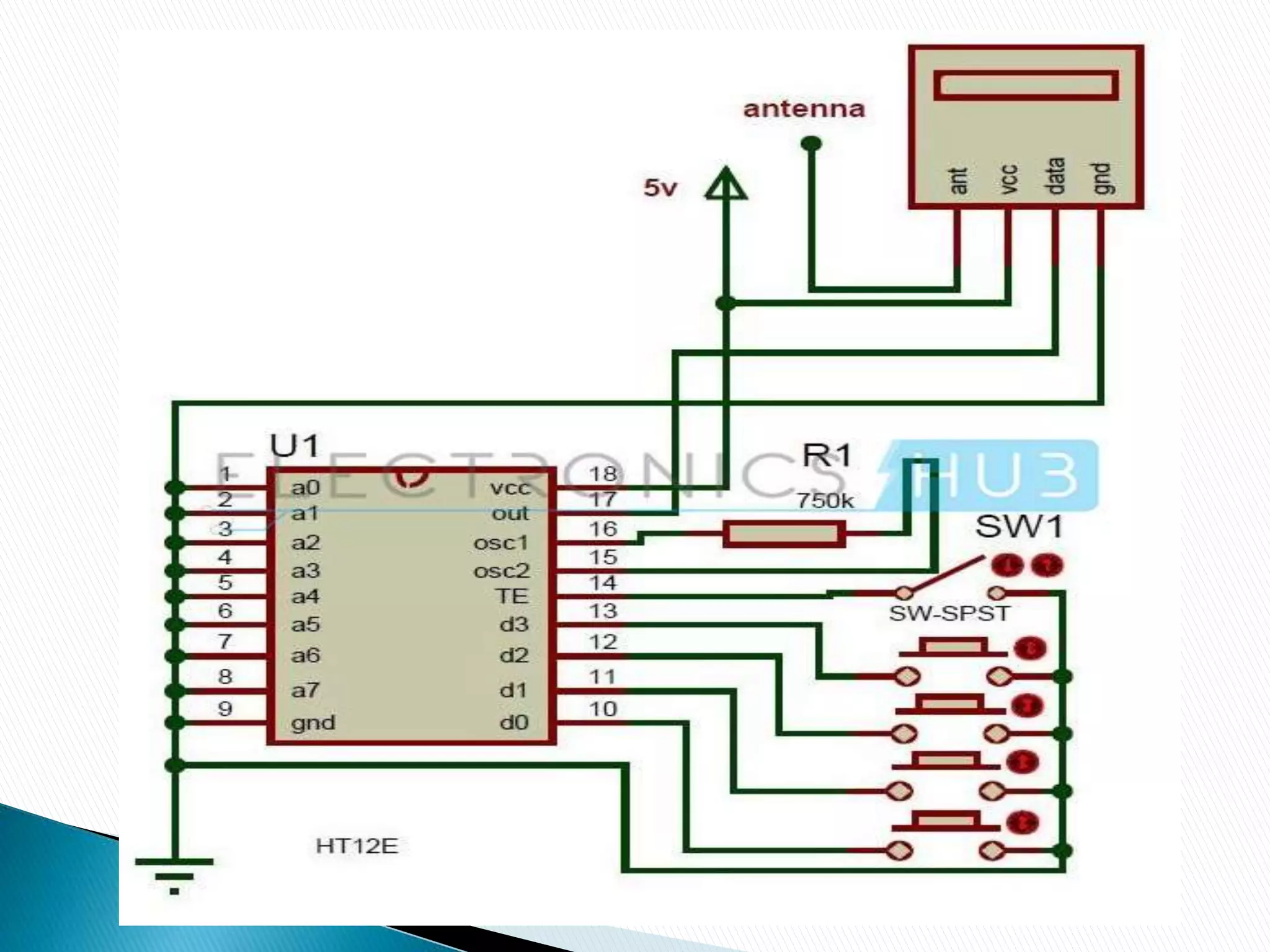
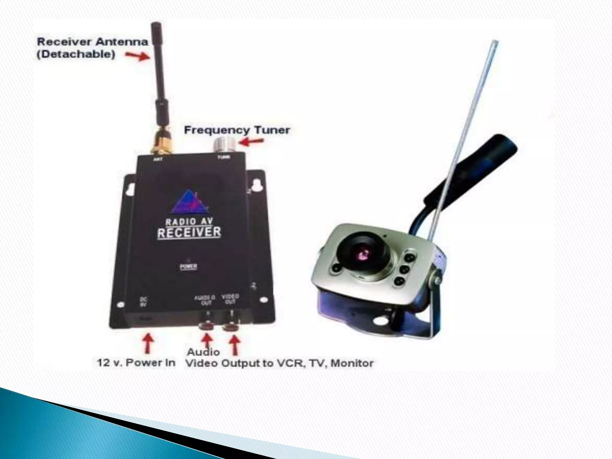
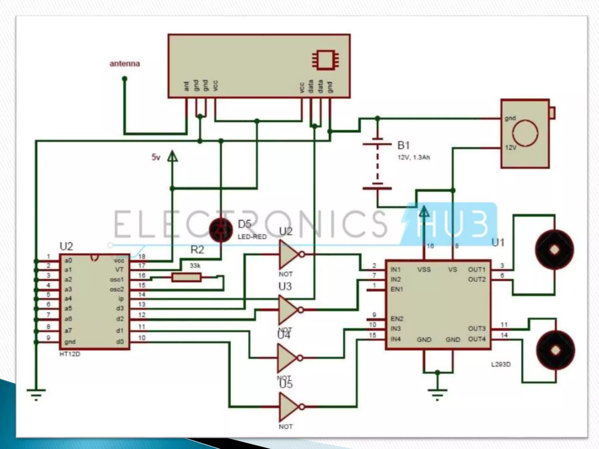
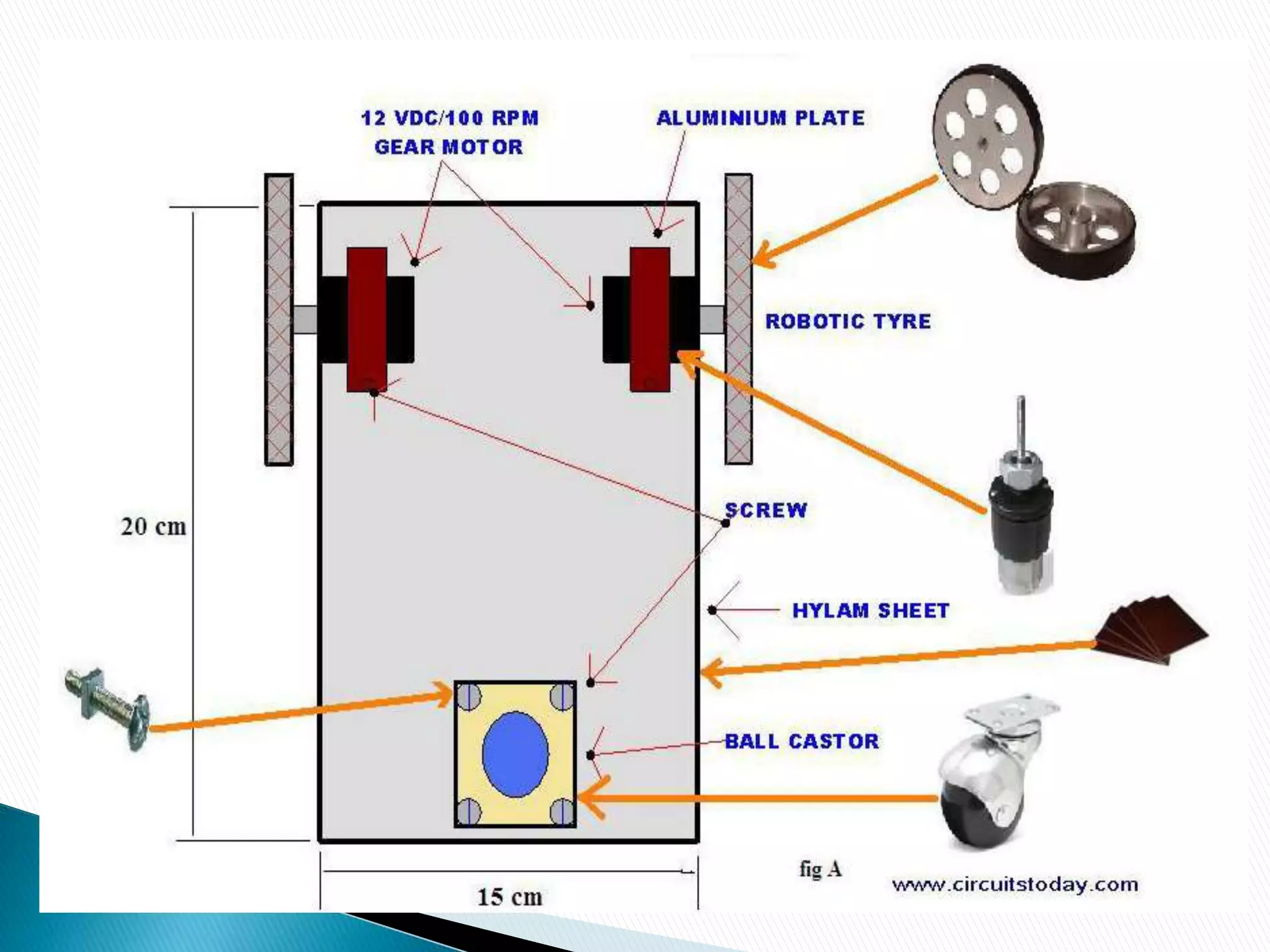
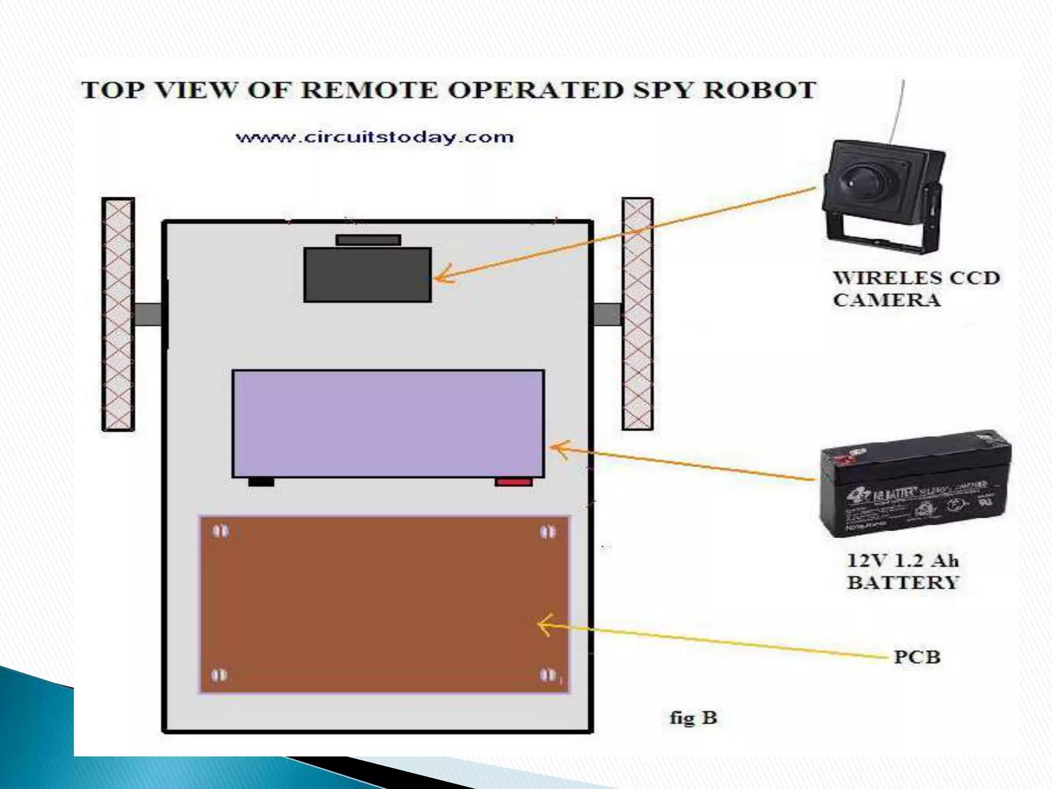
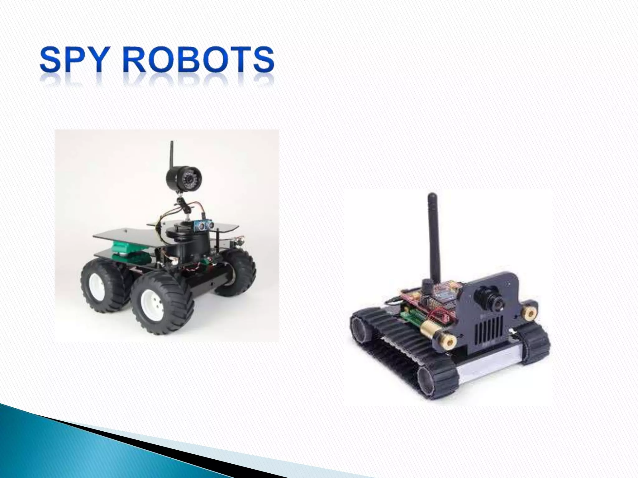
 INTRODUCTION
 CIRCUIT COMPONENTS
 BLOCK DIAGRAM
 CIRCUIT DIAGRAM & DESIGN
 CONSTRUCTION
 HOW TO OPERATE??
 APPLICATIONS
 LIMITATIONS
 SPY ROBOTS
 A remote operated spy robot circuit which can be
controlled by using a wireless remote controller. It can
capture audio and video information’s from the
surroundings and can be sent to a remote station through
RF signals. The maximum range is 125 meters. It
overcomes the limited range of infrared remote
controllers.
 HT12E encoder
 HT12D decoder
 RF 433 MHz Transmitter and Receiver
 L293D motor driver
 Wireless CCD camera
 push buttons – 4
 DC battery – 12V, 1.3 Ah
 9V DC battery
 Robot (structure, body, wheel, etc.)
 Resistors – 33k,750k
 SPST switch – 1
 NOT gates – 4
 Remote operated spy robot has mainly two sections,
one is Remote Control Section used to control the
robot and other one is Video Transmission Section
used to transmit audio and video information. These
two sections are briefly explained below.
 Remote Controlled Section
Here HT12E encoder reads the parallel data
from the switches and gives this data to the RF transmitter
serially. The operating voltage of this encoder is 2.4 to
12V. The RF 434 MHz Transmitter output is up to 8mW at
433.92 MHz frequency. This ASK transmitter accepts both
linear and digital inputs and operating voltage is 1.2V to
12V DC. In remote section, SW1 is used to enable the
transmission.
 Video Transmission Section
In this section, major components are wireless
camera, RF receiver and Robot.
 Wireless CCD Camera
The operating voltage of CCD camera is 12V
DC. The supply for this camera is taken from the motors
battery. The output signals of this camera are in the form
of audio and video. These types of cameras are commonly
available in the market.
 RF Receiver
It ask receiver & receives the serial data
transmitted by the transmitter and gives it decoder to
convert it to the parallel. This parallel data is given to the
L293D motor driver IC to control the robot motors. Here
LED D5 indicates the valid transmission.
 Take a hylam sheet with (20cm*15cm) size.
 Fix two gear motors (12VDC 100rpm) in the hylam
sheet by using aluminium pieces and nut bolts as
shown in the figure below
 Fix the ball castor as shown in the figure below.
 Then fix the battery (12VDC 1.2Ah) on the top of the
spy robot
 Connect two motors to the PCB. The PCB is then
connected to the battery.
 Connect the wireless CCD camera to the battery
 Connect the camera receiver to the TV or computer.
Video information’s will thus appear in the screen.
 Switch on the remote controller and control the spy
robot.
 Give the connections as per the circuit diagram.
 Arrange the wireless CCD camera to the robot.
 Give the wireless camera receiver connection to the computer
or TV.
 Now switch on the both robot and remote supplies.
 Control the spy robot using remote. Now you can observe the
robot surroundings in your computer or TV.
 This spy robot is used to observe the behaviour of wild animals
where human beings cannot reach.
 Used in army applications to detect the bombs.
 Used in industries.
 Barricaded Suspects
 Hostage Rescue
 High-Risk Warrant Service
 Inspection of Ventilation Ducts
 Inspection of Contaminated/Hazardous Environments
 Prison/Jail Riots
 This system does not work for longer distances.
 This is a theoretical circuit and may require some
changes to implement practically.
 Know before you go! The Spy Robots are “throw able”
robots, which serve as your "man on the inside" for a
broad range of military, police, security, and rescue
applications.
 In any dangerous, hostile, or confined environment,
you’ll instantly get critical visual intelligence that can
save lives and reduce property damage.
REMOTE OPERATED SPY ROBO PPT

REMOTE OPERATED SPY ROBO PPT

  • 2.
     INTRODUCTION  CIRCUITCOMPONENTS  BLOCK DIAGRAM  CIRCUIT DIAGRAM & DESIGN  CONSTRUCTION  HOW TO OPERATE??  APPLICATIONS  LIMITATIONS  SPY ROBOTS
  • 3.
     A remoteoperated spy robot circuit which can be controlled by using a wireless remote controller. It can capture audio and video information’s from the surroundings and can be sent to a remote station through RF signals. The maximum range is 125 meters. It overcomes the limited range of infrared remote controllers.
  • 4.
     HT12E encoder HT12D decoder  RF 433 MHz Transmitter and Receiver  L293D motor driver  Wireless CCD camera  push buttons – 4  DC battery – 12V, 1.3 Ah  9V DC battery  Robot (structure, body, wheel, etc.)  Resistors – 33k,750k  SPST switch – 1  NOT gates – 4
  • 6.
     Remote operatedspy robot has mainly two sections, one is Remote Control Section used to control the robot and other one is Video Transmission Section used to transmit audio and video information. These two sections are briefly explained below.
  • 7.
     Remote ControlledSection Here HT12E encoder reads the parallel data from the switches and gives this data to the RF transmitter serially. The operating voltage of this encoder is 2.4 to 12V. The RF 434 MHz Transmitter output is up to 8mW at 433.92 MHz frequency. This ASK transmitter accepts both linear and digital inputs and operating voltage is 1.2V to 12V DC. In remote section, SW1 is used to enable the transmission.
  • 9.
     Video TransmissionSection In this section, major components are wireless camera, RF receiver and Robot.  Wireless CCD Camera The operating voltage of CCD camera is 12V DC. The supply for this camera is taken from the motors battery. The output signals of this camera are in the form of audio and video. These types of cameras are commonly available in the market.
  • 11.
     RF Receiver Itask receiver & receives the serial data transmitted by the transmitter and gives it decoder to convert it to the parallel. This parallel data is given to the L293D motor driver IC to control the robot motors. Here LED D5 indicates the valid transmission.
  • 13.
     Take ahylam sheet with (20cm*15cm) size.  Fix two gear motors (12VDC 100rpm) in the hylam sheet by using aluminium pieces and nut bolts as shown in the figure below  Fix the ball castor as shown in the figure below.
  • 15.
     Then fixthe battery (12VDC 1.2Ah) on the top of the spy robot  Connect two motors to the PCB. The PCB is then connected to the battery.  Connect the wireless CCD camera to the battery  Connect the camera receiver to the TV or computer. Video information’s will thus appear in the screen.  Switch on the remote controller and control the spy robot.
  • 17.
     Give theconnections as per the circuit diagram.  Arrange the wireless CCD camera to the robot.  Give the wireless camera receiver connection to the computer or TV.  Now switch on the both robot and remote supplies.  Control the spy robot using remote. Now you can observe the robot surroundings in your computer or TV.
  • 18.
     This spyrobot is used to observe the behaviour of wild animals where human beings cannot reach.  Used in army applications to detect the bombs.  Used in industries.  Barricaded Suspects  Hostage Rescue  High-Risk Warrant Service  Inspection of Ventilation Ducts  Inspection of Contaminated/Hazardous Environments  Prison/Jail Riots
  • 19.
     This systemdoes not work for longer distances.  This is a theoretical circuit and may require some changes to implement practically.
  • 21.
     Know beforeyou go! The Spy Robots are “throw able” robots, which serve as your "man on the inside" for a broad range of military, police, security, and rescue applications.  In any dangerous, hostile, or confined environment, you’ll instantly get critical visual intelligence that can save lives and reduce property damage.