Downloaded 541 times

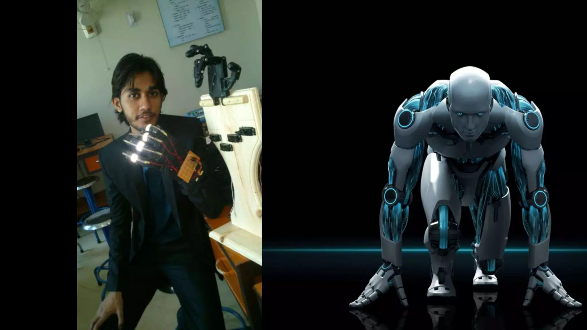

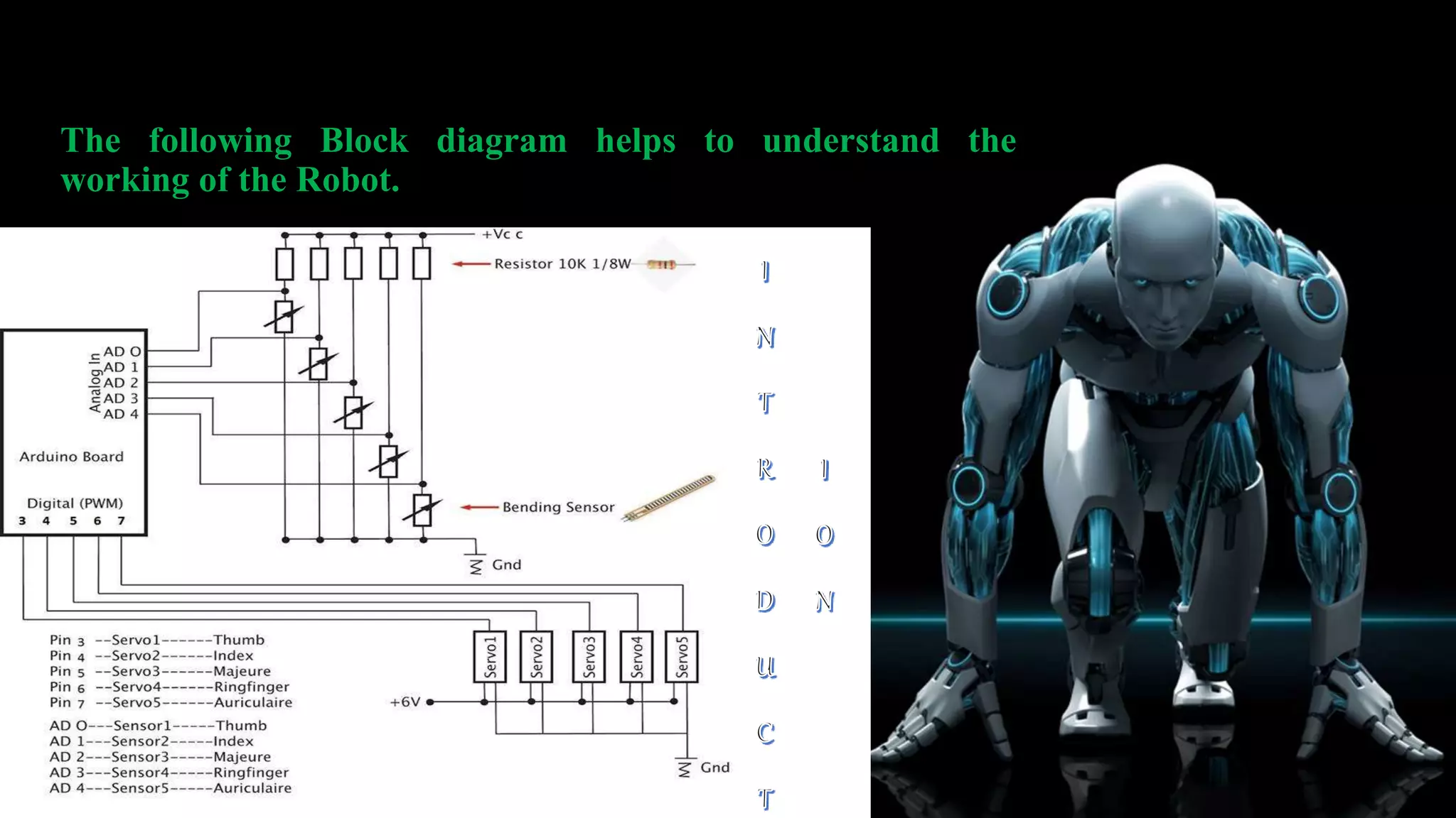

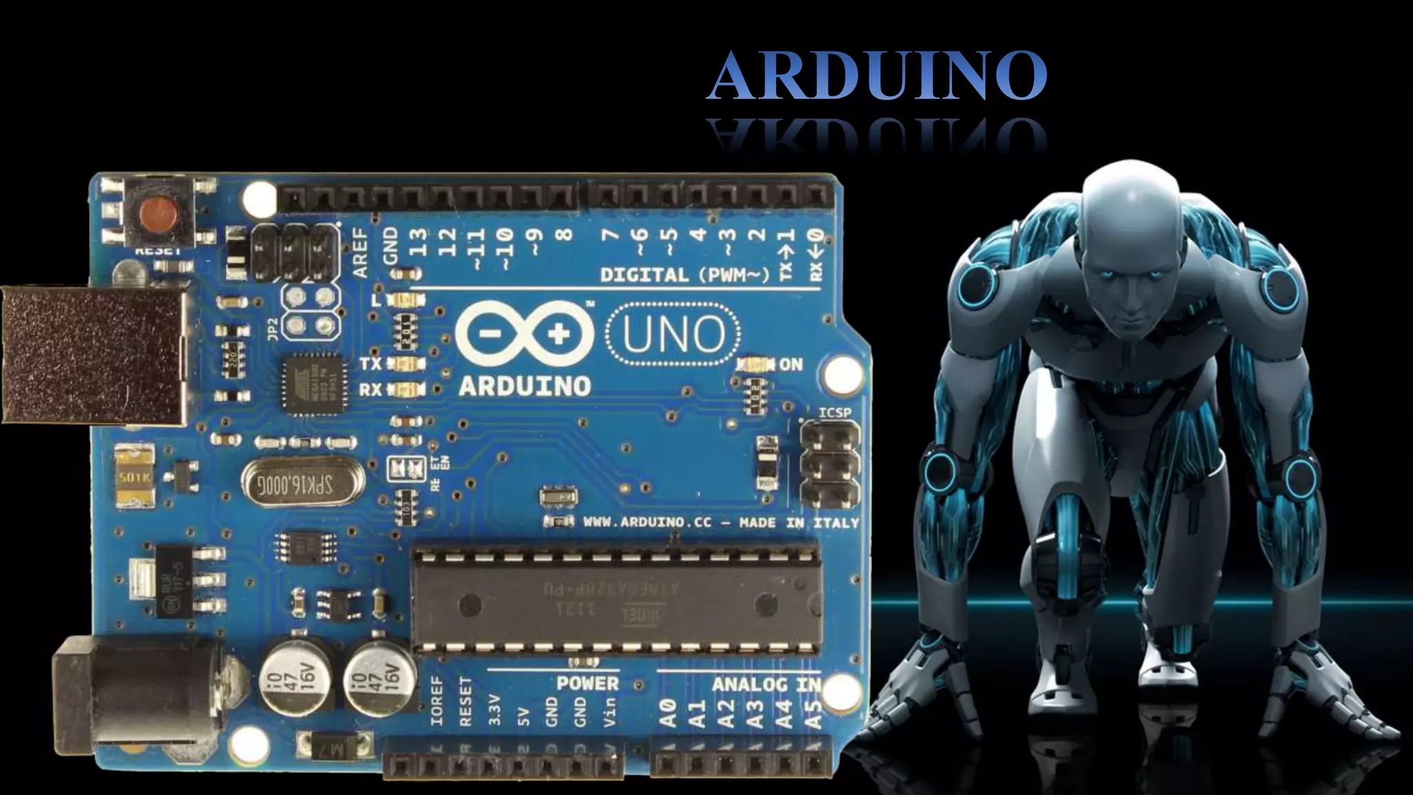
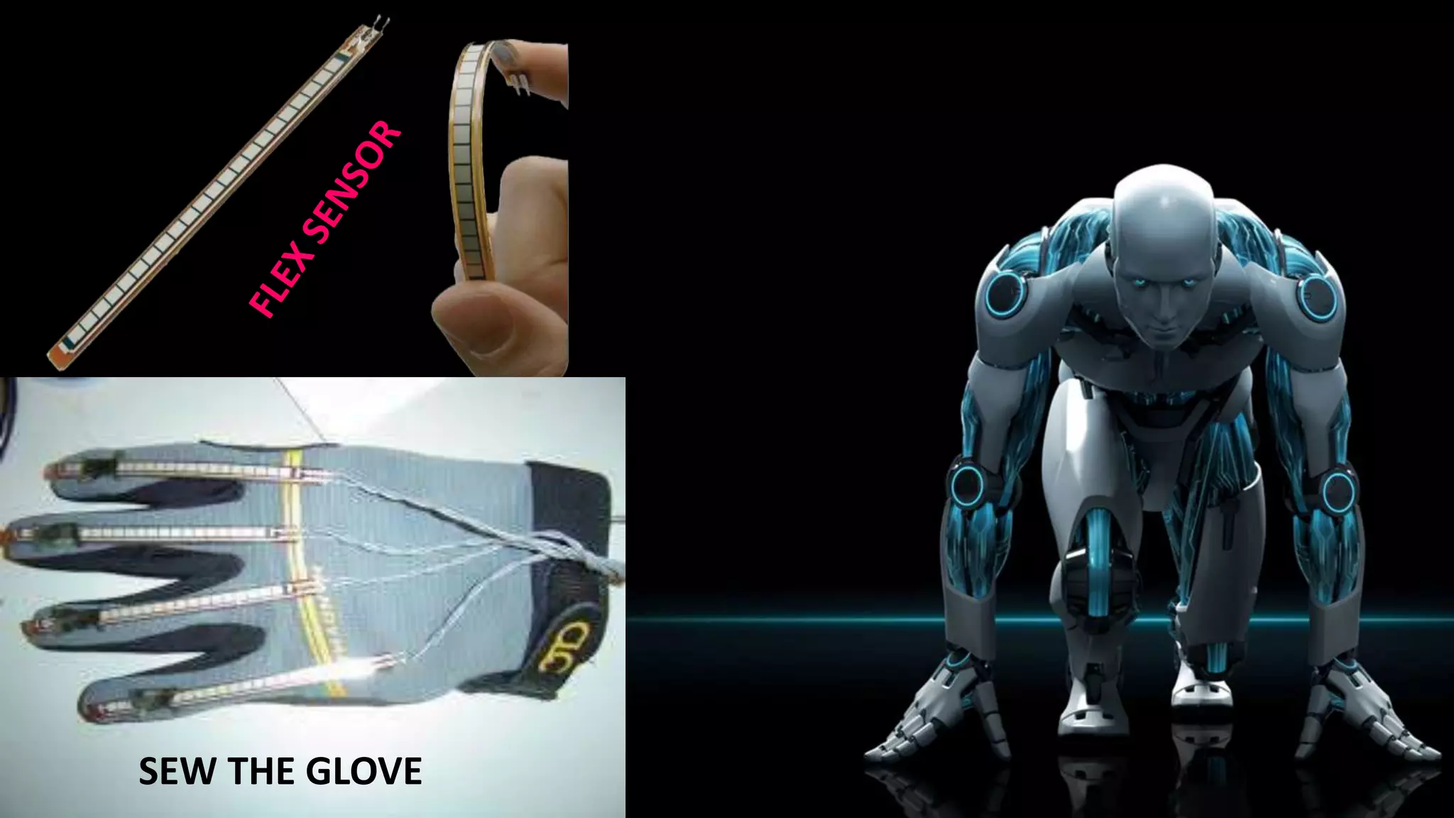


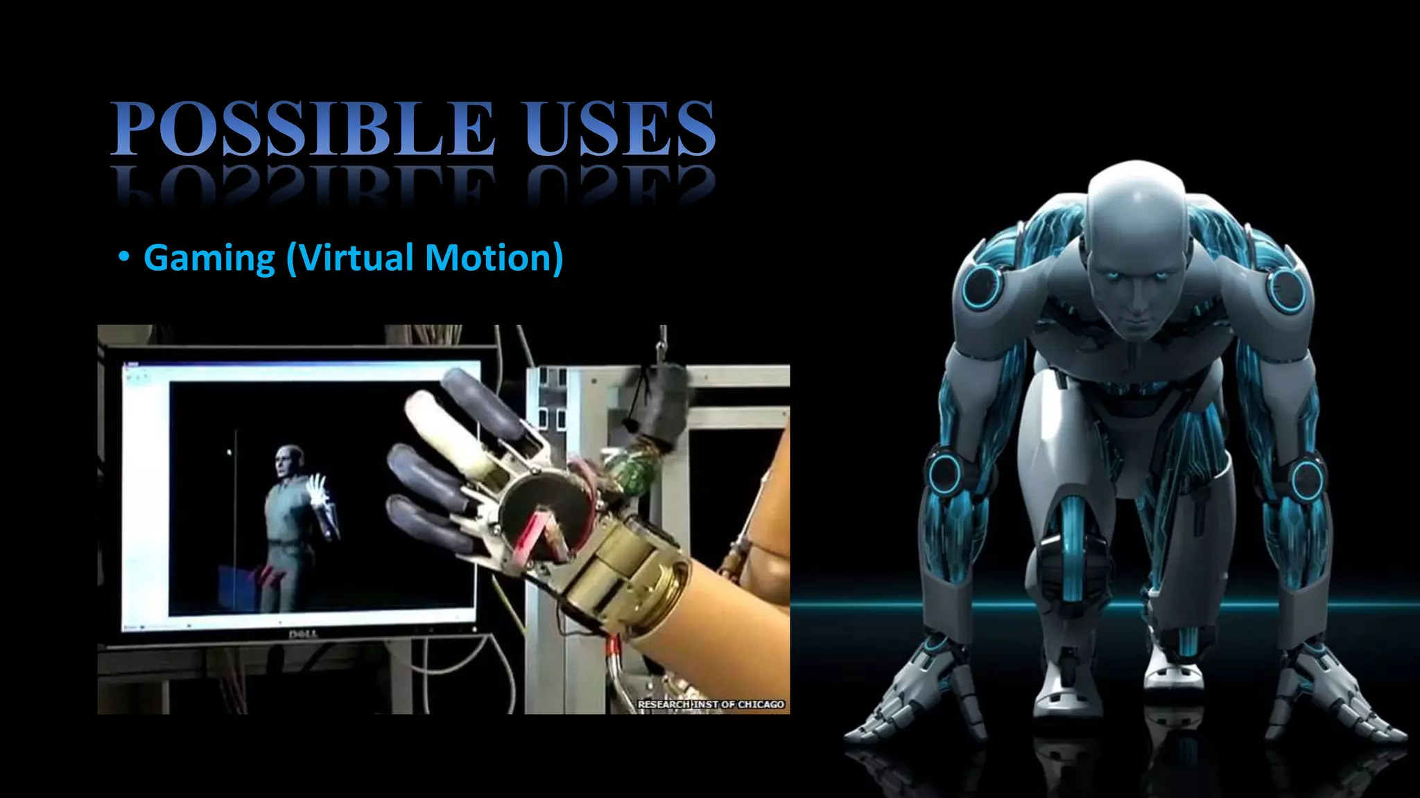

This robotic hand can be controlled by human hand gestures through a wired connection. Flex sensors on a glove record hand movements and send the data to an Arduino microcontroller via an encoder. The microcontroller controls servo motors in the robotic hand to mimic the movements of the human hand, allowing interactive control. While the system works responsively, the flex sensors and servo motors have limited lifetimes that require careful maintenance for continued operation.