The document discusses the concept and structure of an obstacle avoidance robot within the field of robotics, emphasizing its ability to navigate around obstacles autonomously using various components like IR sensors and microcontrollers. It highlights the robot's applications in industries and mentions potential improvements such as adding a camera. Additionally, it outlines the electrical and mechanical designs involved in building such a robot.
What Is “Robotics”?
The word robotics is used to collectively
define a field in engineering that covers the
mimicking of various human characteristics.
It must be able to perform certain tasks we
set for it.
The desired task must be achieved within
some given limitations.
It may be human controlled or automatic.
Why Robotics?
Mobile robots perform various ways of
tasks to serve humans
No human guidance is required
This sort of project is very much useful in
the industries where the automated
supervision is required
5.
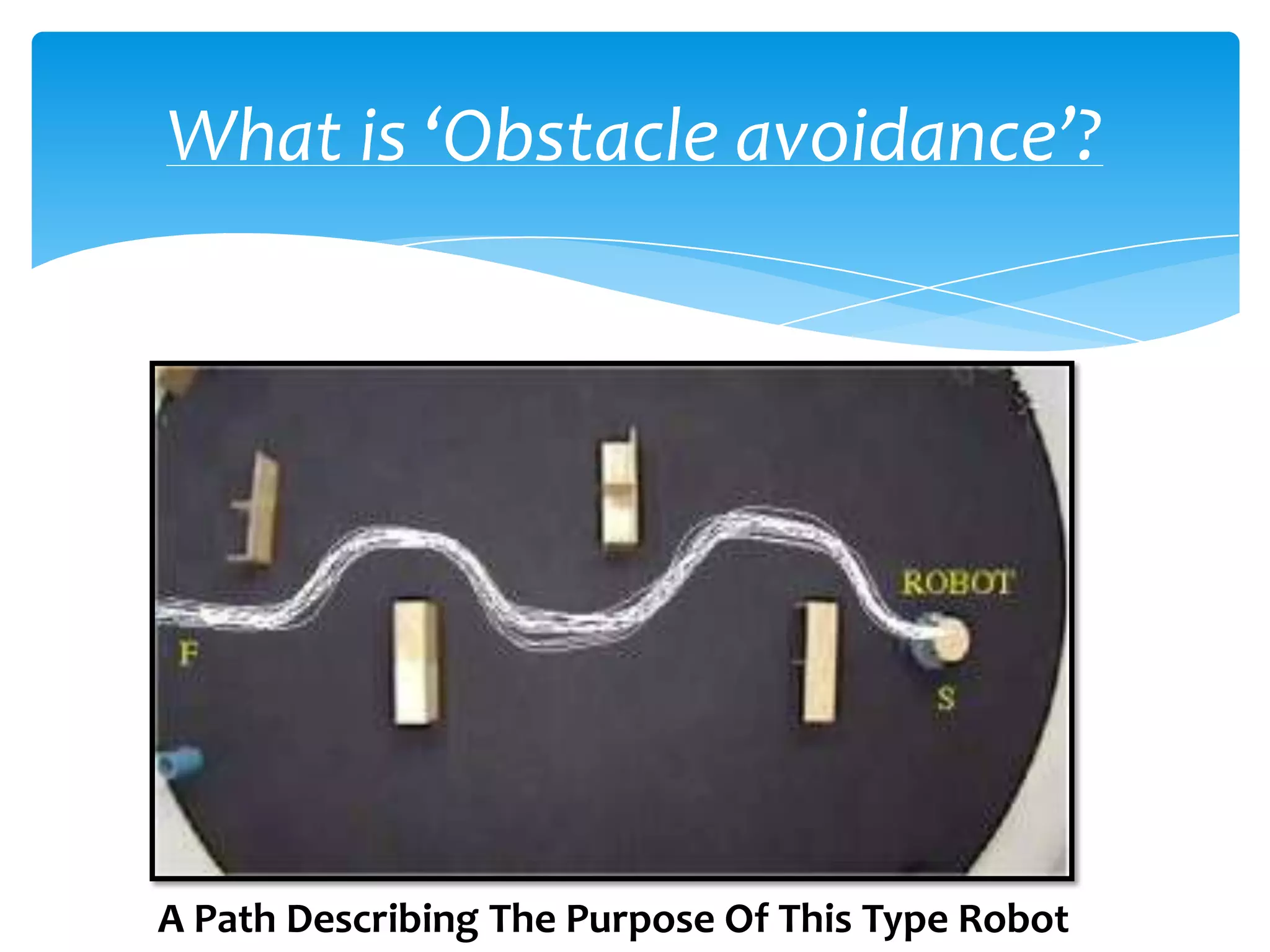
What is ‘Obstacleavoidance’?
A Path Describing The Purpose Of This Type Robot
6.
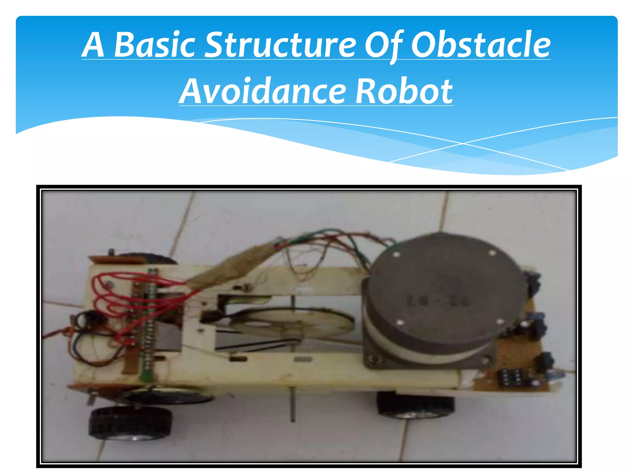
OUR ROBOT:-
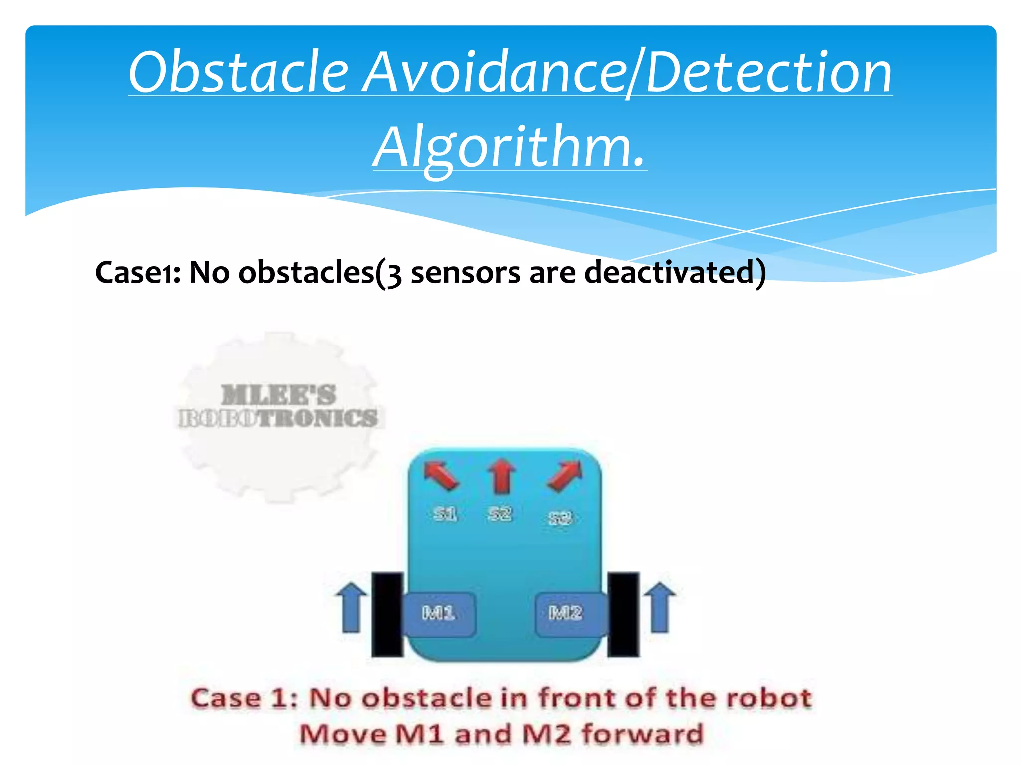
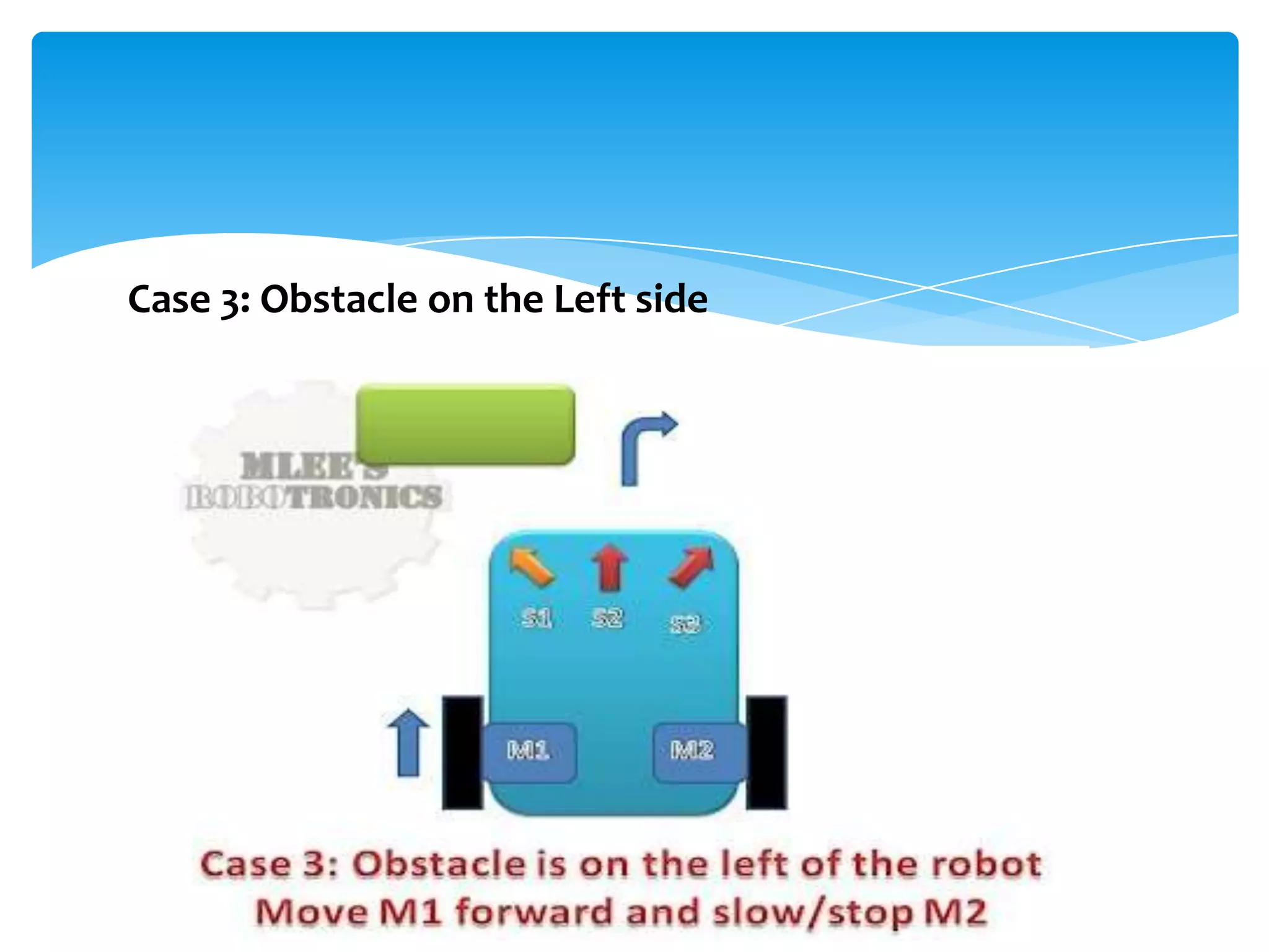
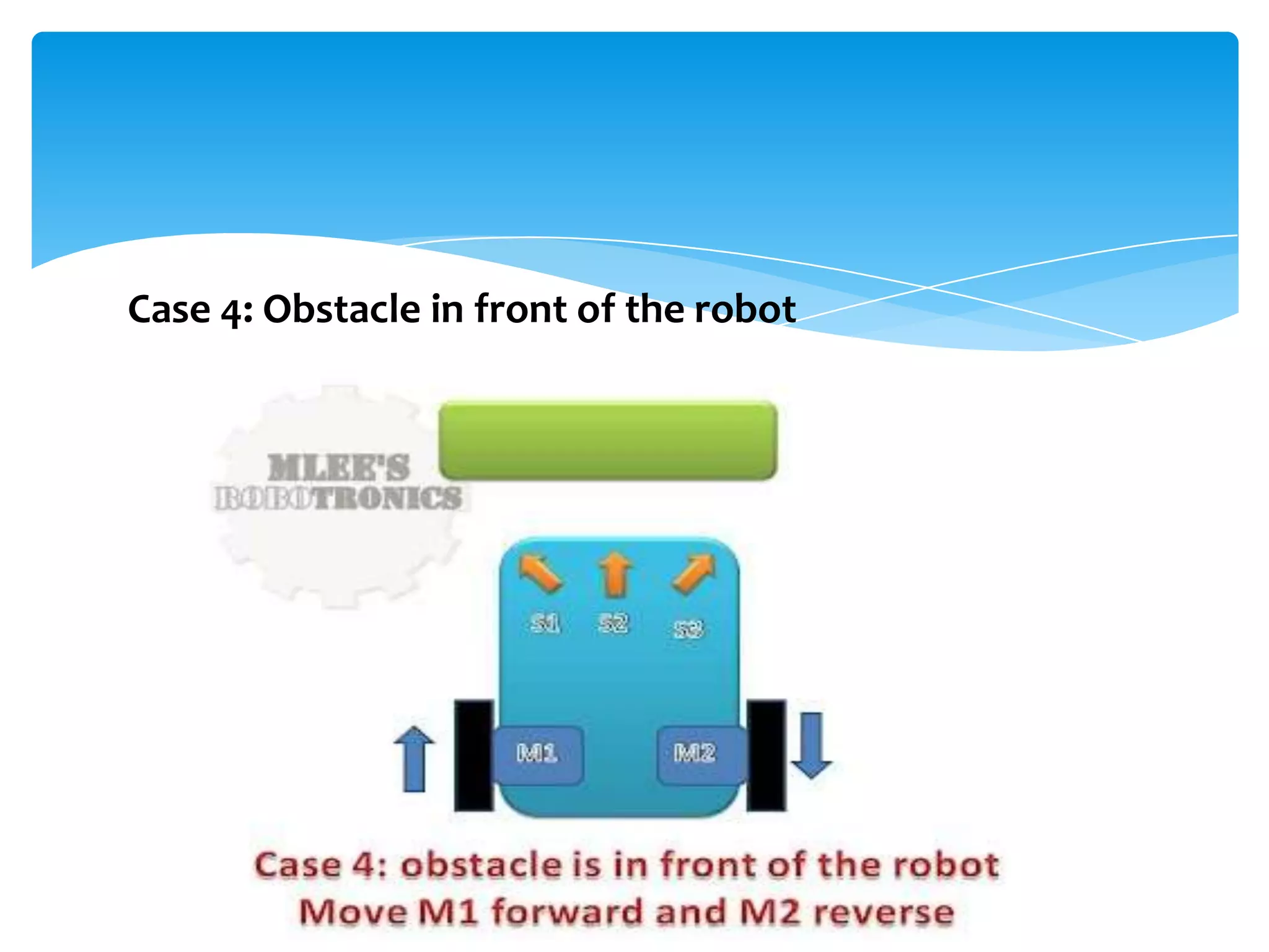
In this project our robot senses any obstacle
in its path, avoids it and resumes its running
Involves the pre-computation of an
obstacle-free path which a controller guides
the robot
7.
COMPONENTS:-
IR Sensor(Transmitter and receiver)
Microcontroller
Driver IC
Motor
IR Sensor:-
About
(IR) sensors based on reflected amplitude of
the surrounding objects
Non-linear and depends on the reflectance
characteristics of the object surface
IR sensors able to accurately measure
distances with reduced response times
11.
IR Sensor:-
Types:
ACTIVE INFRARED SENSORS
Break Beam Sensors
Reflectance Sensors
12.
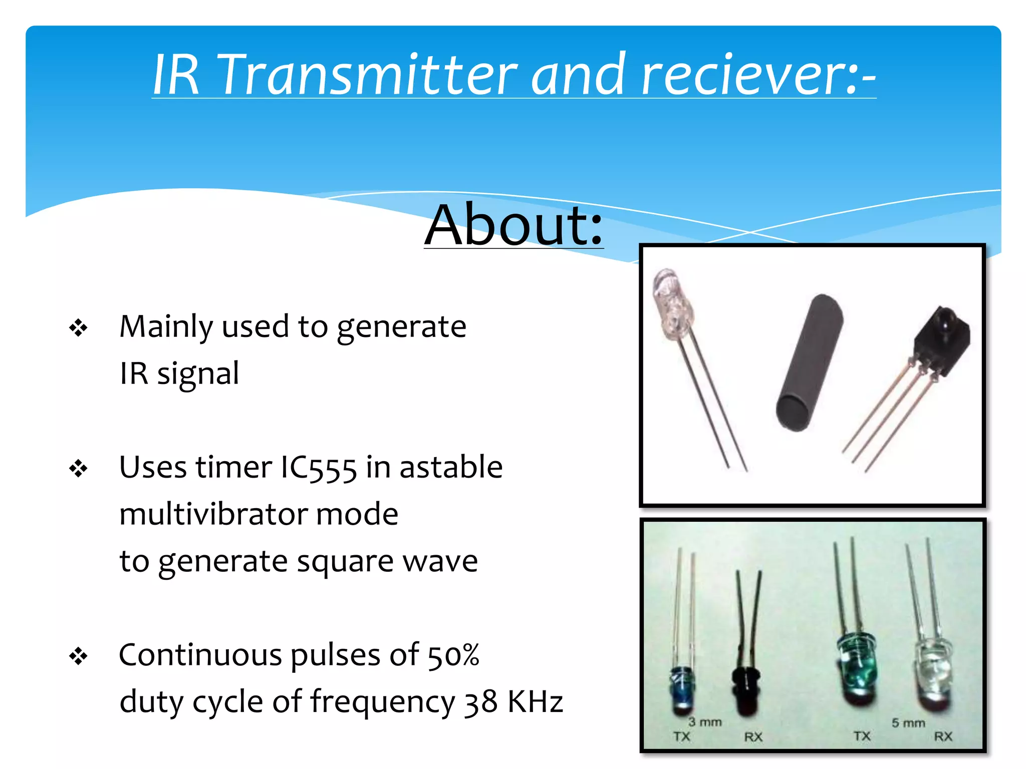
IR Transmitter andreciever:-
About:
Mainly used to generate
IR signal
Uses timer IC555 in astable
multivibrator mode
to generate square wave
Continuous pulses of 50%
duty cycle of frequency 38 KHz
13.
IR Sensor:-
Application:
Widely used for distance measurement
purposes
Surface feature detection
Barcode decoding
As a tracking system
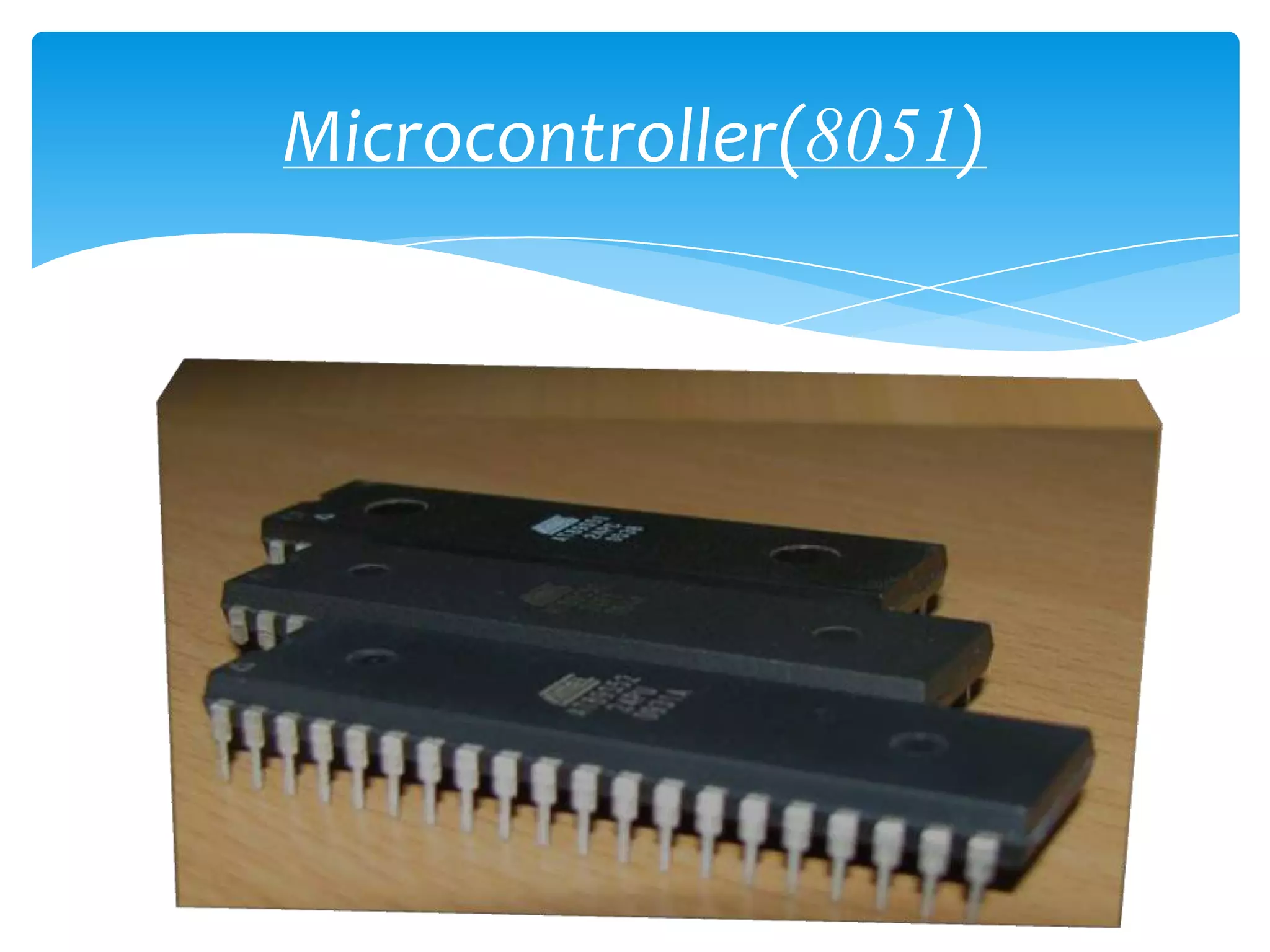
Microcontroller(8051):-
About:
Single integrated circuit containing a processor
core, memory, and
programmable input/output peripherals
Program memory in the form of NOR
flash or OTPROM is also often included on chip
Microcontrollers are used in automatically
controlled products and devices
Make it economical to digitally control even
more devices and processes
16.
Driver(L293D):-
About:
The L293D is a quadruple half H-bridge
bidirectional motor driver IC
Can drive current of up to 600mA with
voltage range of 4.5 to 36 volts
Drive small DC-Geared motors, bipolar
stepper motor
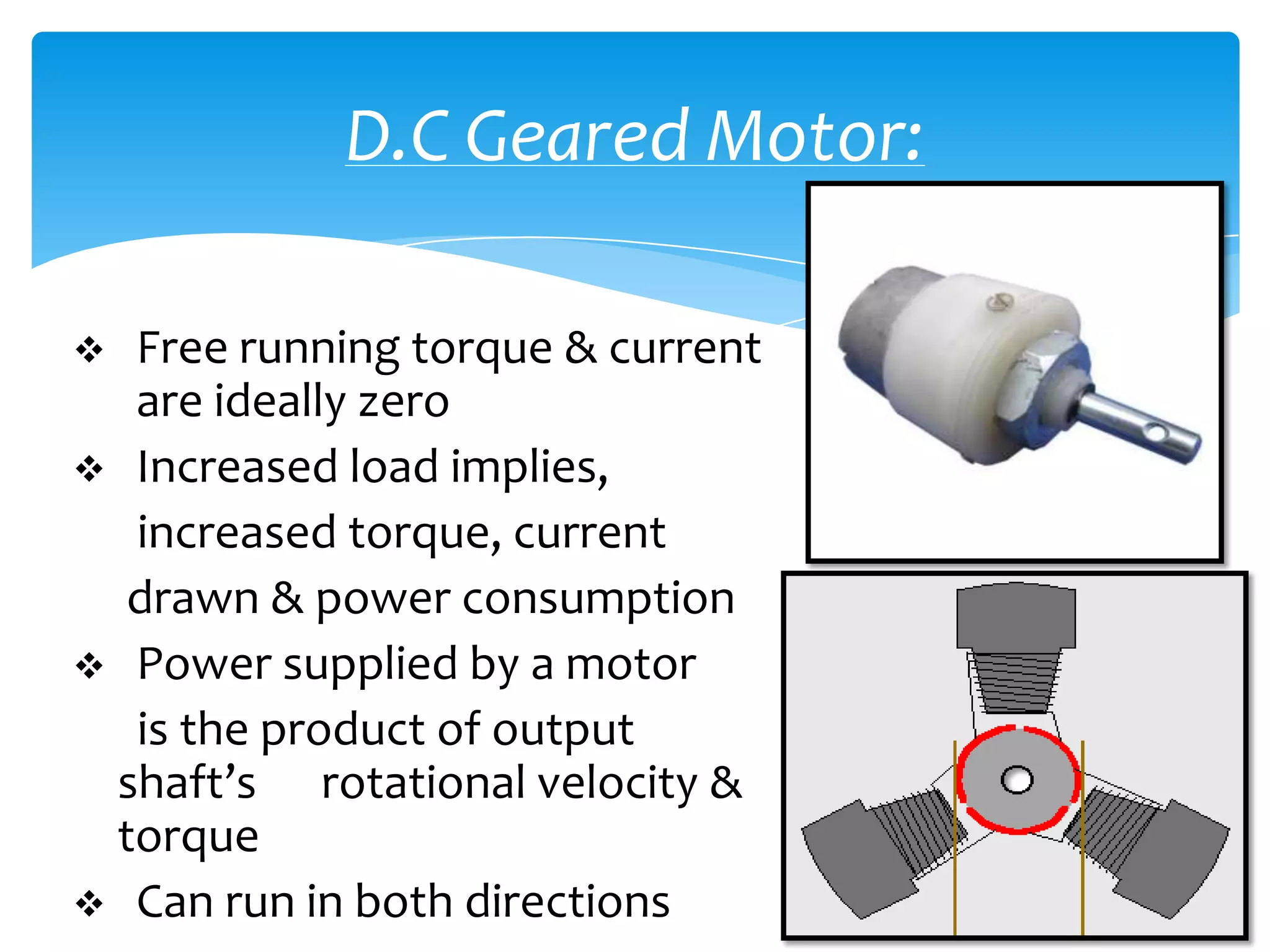
D.C Geared Motor:
Free running torque & current
are ideally zero
Increased load implies,
increased torque, current
drawn & power consumption
Power supplied by a motor
is the product of output
shaft’s rotational velocity &
torque
Can run in both directions
19.
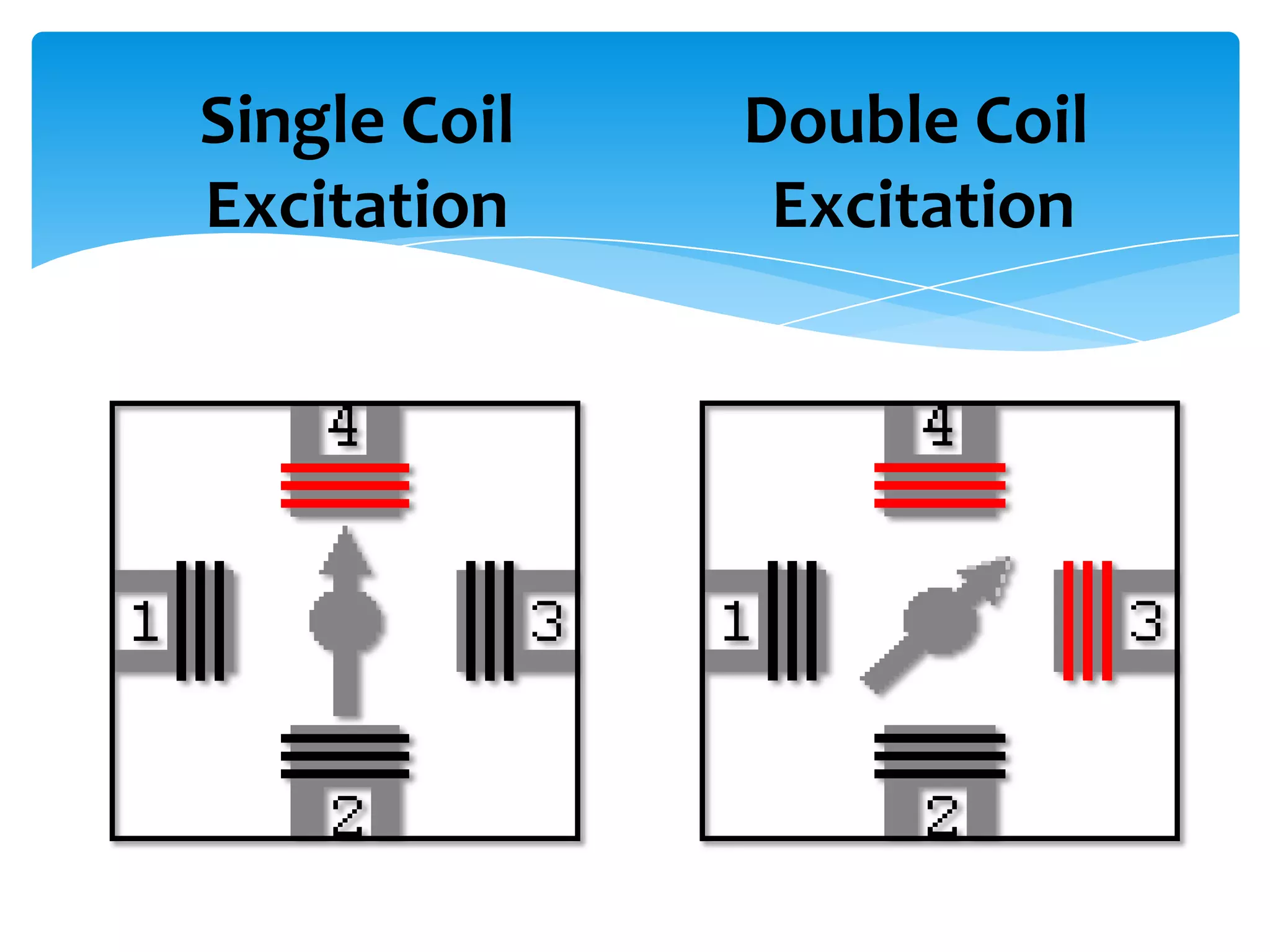
Stepper motor:
Used for measured rotation
Can be held at a particular
position of the shaft
Ideal for many
autonomous robots
requiring
higher precision
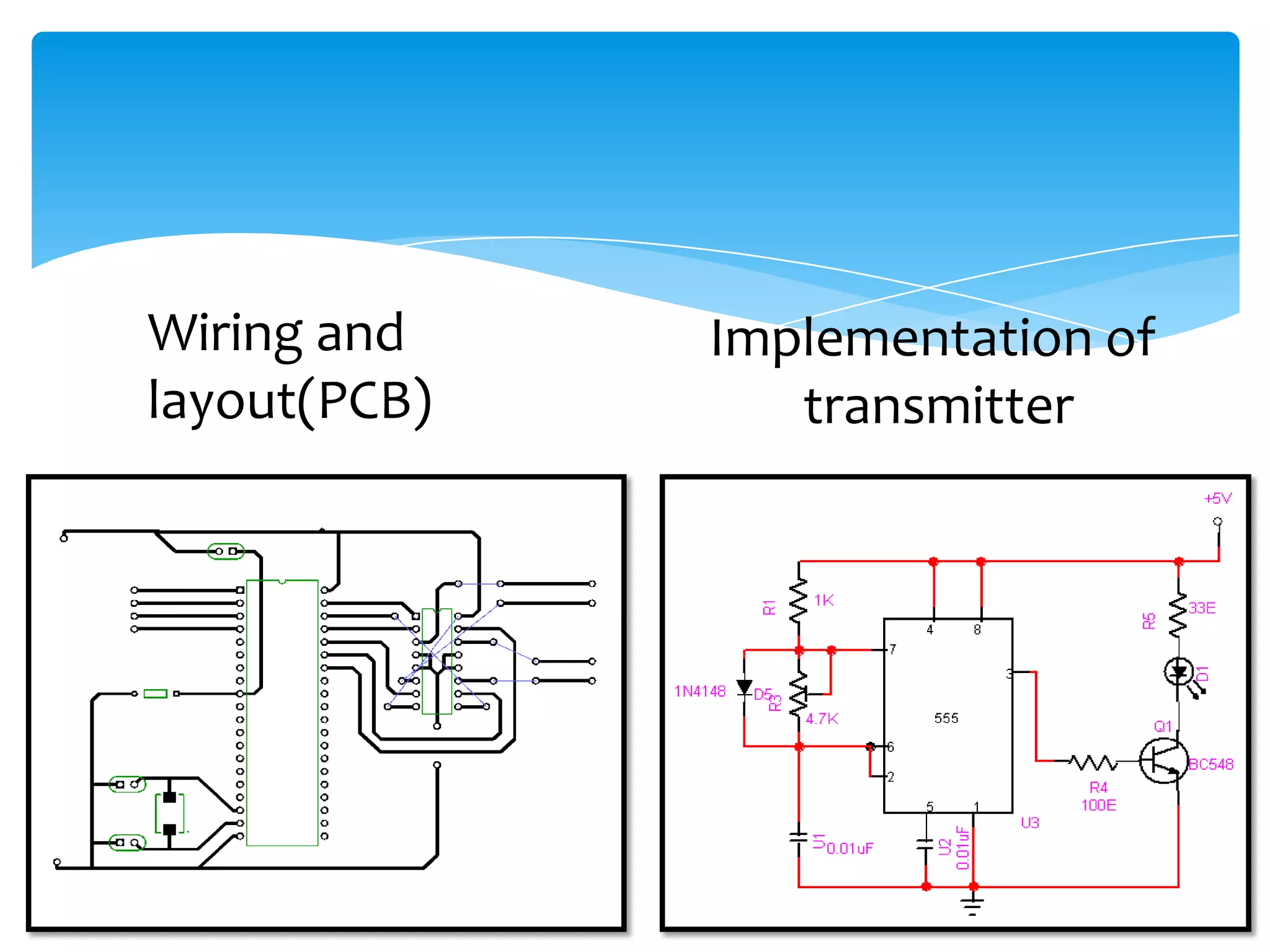
Wiring and Implementation of
layout(PCB) transmitter
27.
Power Supply System:
Suitable power source is needed to run the
robots
Mobile robots are most suitably powered by
batteries
The weight and energy capacity of the
batteries may become the determinative
factor of its performance
28.
MECHANICAL DESIGN:
Design of chassis/body
Alignment of circular wheels
Fixing motors
Screwing of PCB
29.
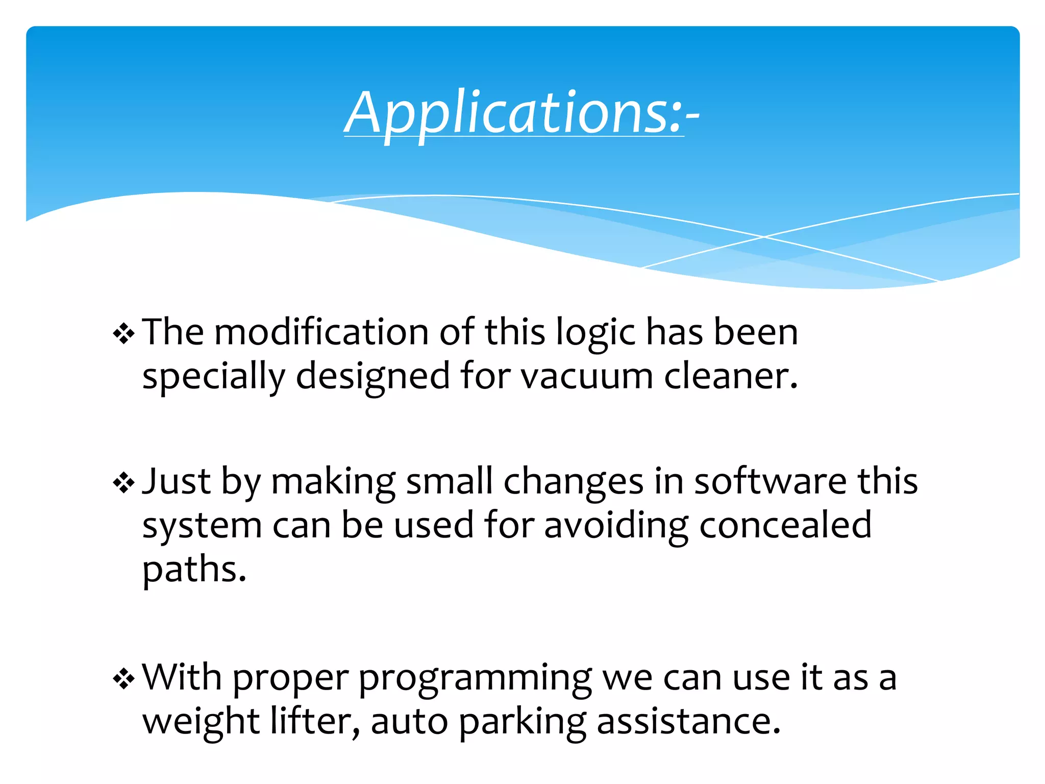
Applications:-
The modificationof this logic has been
specially designed for vacuum cleaner.
Just by making small changes in software this
system can be used for avoiding concealed
paths.
With proper programming we can use it as a
weight lifter, auto parking assistance.