Download to read offline

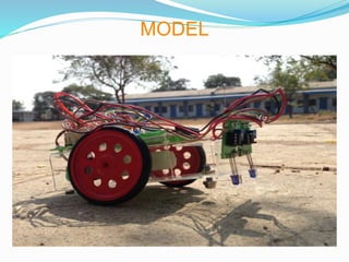
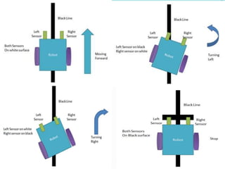
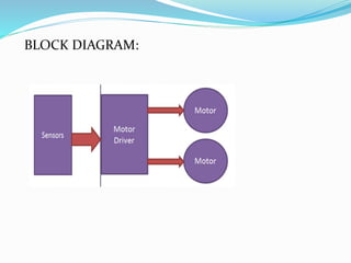


This document describes a line following robot project created by students at the Shri Govindram Seksaria Institute of Technology and Science Indore. The robot uses 3 IR sensor pairs and 2 motors to follow a black line on a white surface. It works by using the IR sensors to detect the line and send signals to the motor control circuitry, which instructs the motors to move the robot forward or turn as needed to stay on the line. The document discusses the components, working model, block diagram, applications and conclusions of the project. It proposes areas for future work, such as using a microcontroller and color sensors to add obstacle avoidance and other capabilities to the robot.