Downloaded 1,901 times


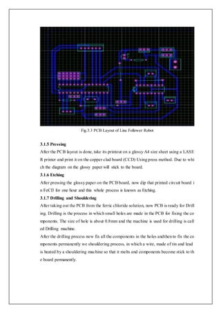


![Chapter 6
BIBLOGRAPHY
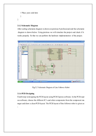
6.1 References
[1].Bajestani, S.E.M., Vosoughinia, A., “Technical Report of Building a Line
Follower Robot” International Conference on Electronics and Information
Engineering (ICEIE 2010), vol 1, pp v1-1 v1-5, 2010.
[2].Bong. D.M.K, “Automatic Guided Vehicle System” in Department of
Electrical Engineering, University Tenega Nasional, Malaysia, P.41, 2004.
[3]. Colak, I., Yildirim, D.,”Evolving a Line Following Robot to use in shopping
centers for entertainment”,Industrial Electronics, 2009. IECON ’09. 35th
Annual Conference of IEEE,pp.3803 – 3807,3-5 Nov. 2009.
[4]. Development and Applications of Line Following Robot Based Health Care
Management System Deepak Punetha, Neeraj Kumar, Vartika Mehta,
International Journal of Advanced Research in Computer Engineering &
Technology (IJARCET), Volume 2, Issue 8, August 2013 p2446-2450
[5].Health Care System – Liverpool-ha.org.uk. Retrieved 2011-08-06.
[6]. http://en.wikipedia.org/wiki/Health_system.
[7]. K.A.Unyelioglu, C.Hatipoglu, and U.Ozguner, “Design and analysis of a
line following robot controller”, IEEE Trans. Control System Technol., Vol.5,
no.1, pp.127-134, 1997 (Pubitemid 127770536)
[8]. M.Mehdi Samaatiyan, Mehran Pakdaman “Design and implementation of
line follower robot”, Mazandaran Institute of Technology, Iran, 2009,
Second International Conference on Computers and Electrical Engineering.
[9]. Priyank Patil, “AVR Line Following Robot,” Department of Information
Technology K. J. Somaiya College of Engineering Mumbai, India.](https://image.slidesharecdn.com/finalreportoflinefollowerrobot-161218113043/85/Final-report-of-line-follower-robot-29-320.jpg)
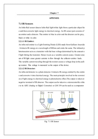

The document is a project report on a line-following robot developed by students at Rajiv Gandhi Proudyogiki Vishwavidyalaya. It details the design and implementation of a microcontroller-based robot that autonomously delivers medicine within hospitals using infrared sensors for line detection. The project aims to automate material supply processes to enhance efficiency in patient care and reduce manual labor for hospital staff.