Download to read offline
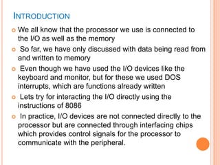

![ There are two schemes for connecting an I/O device to the
processor
Memory Mapped I/O :
In this scheme, the I/O device has the same address
space and addressing scheme as memory.
For example, given the instruction MOV AL, [3456H], the
address 3456H may be a memory location or the address
of an I/O device.
So I/O addressing does not need any special instructions.
Peripheral or Isolated I/O:
Also referred to as ‘I/O mapped I/O’ .
Here, there are special instructions catering to input and
output devices
The address space is disjoint and separate from the
memory address space. (Detail in Chapter 7)](https://image.slidesharecdn.com/chapter5-programmingconceptsiv-170612061535/85/Chapter-5-programming-concepts-iv-6-320.jpg)


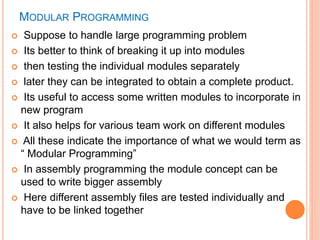


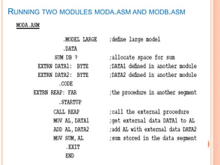
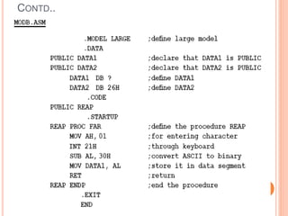
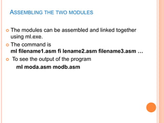


The document discusses modular programming concepts in assembly language. It explains that large programming problems can be broken down into modules that are tested individually and then linked together. It outlines some issues that must be resolved for successful linking, such as data access permissions and external labels. The directives PUBLIC and EXTRN are described as ways to declare data, procedures, and labels that need to be accessed externally or are defined externally. The document provides examples of how to use these directives and assemble/link multiple modules into a single program.