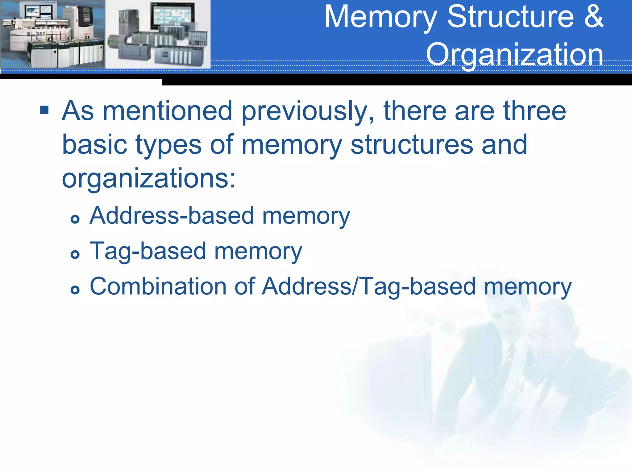
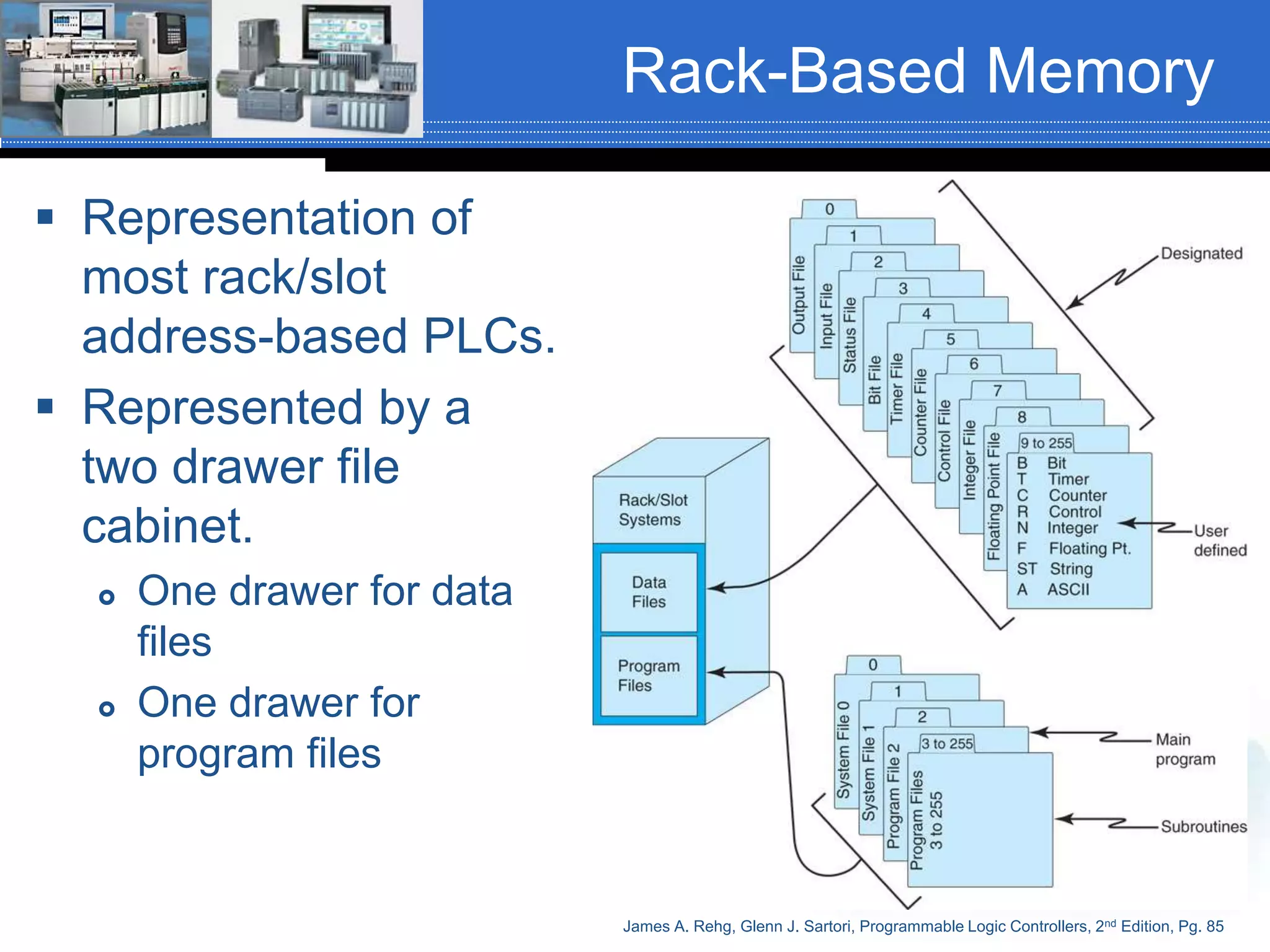
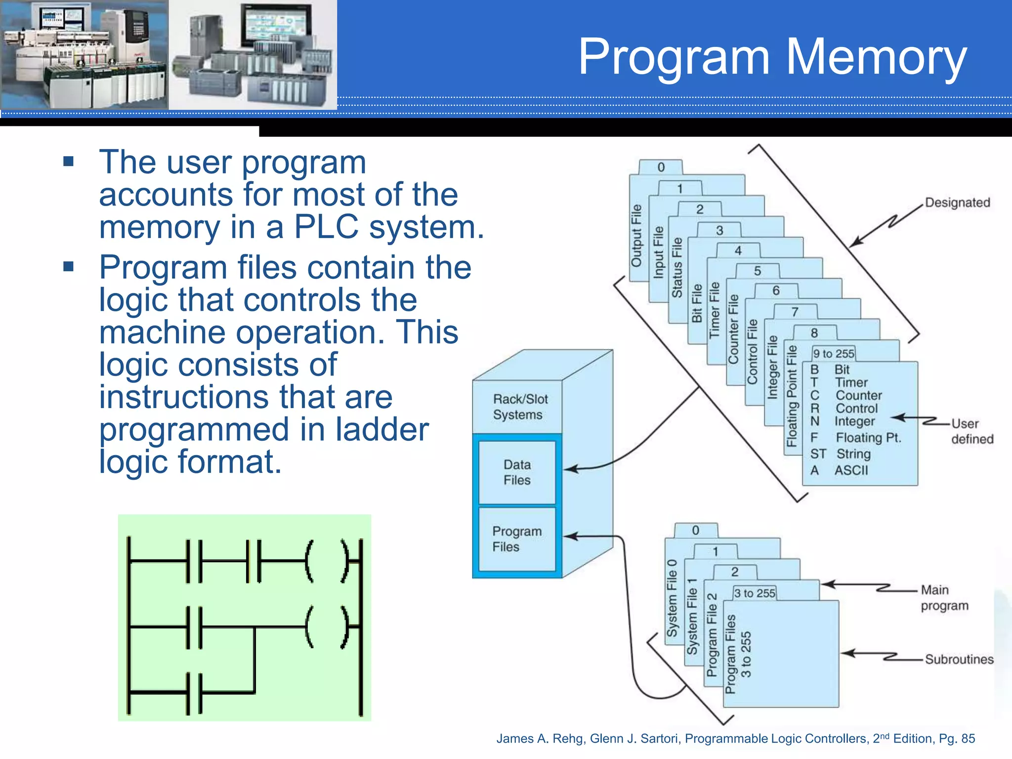
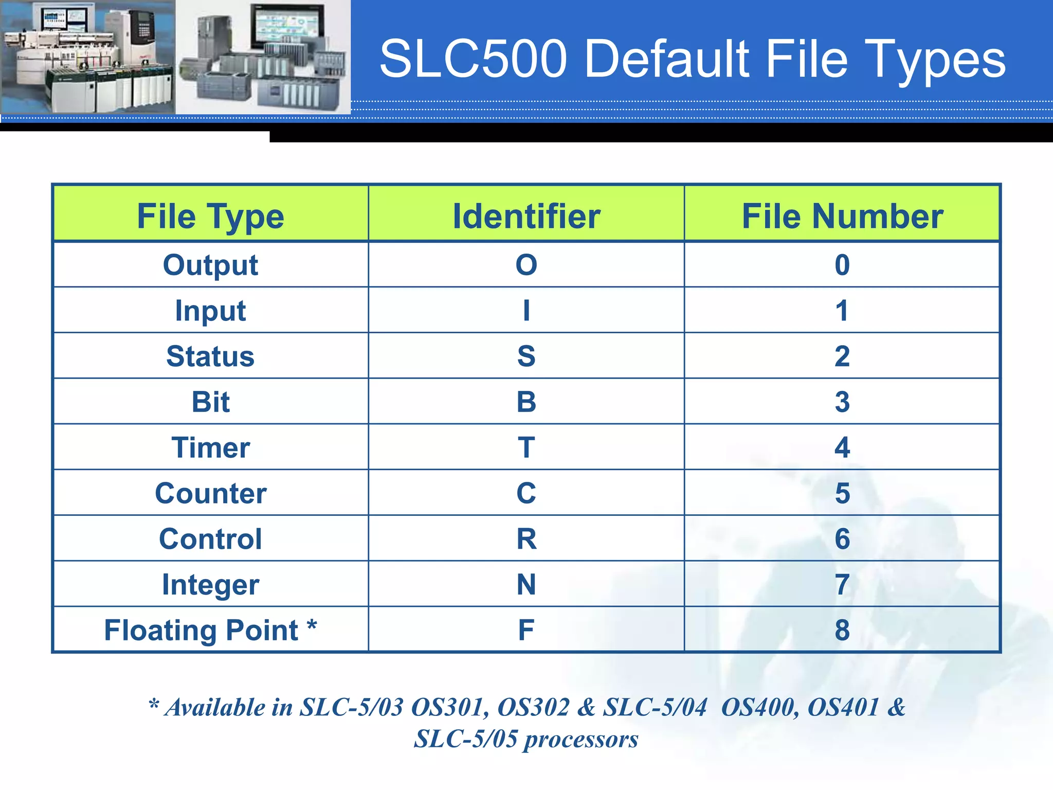
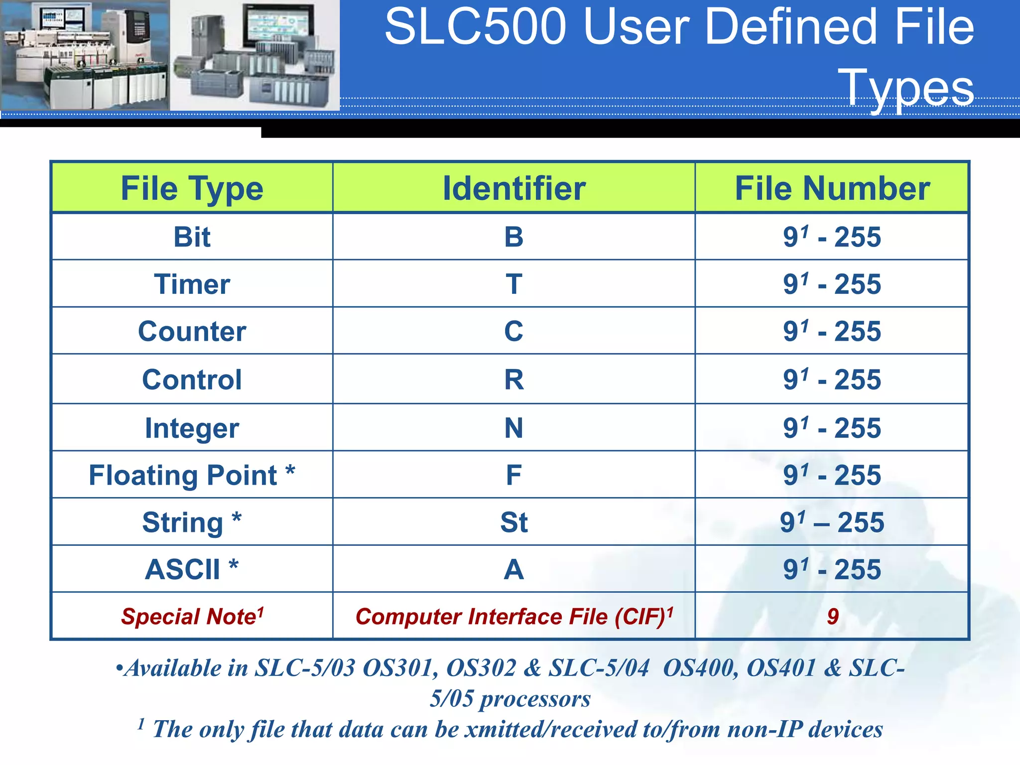
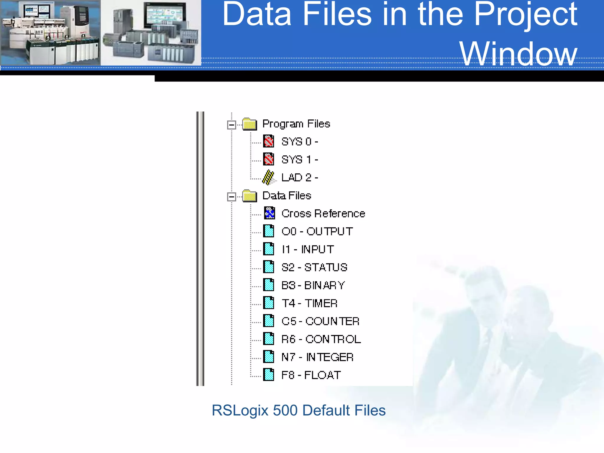
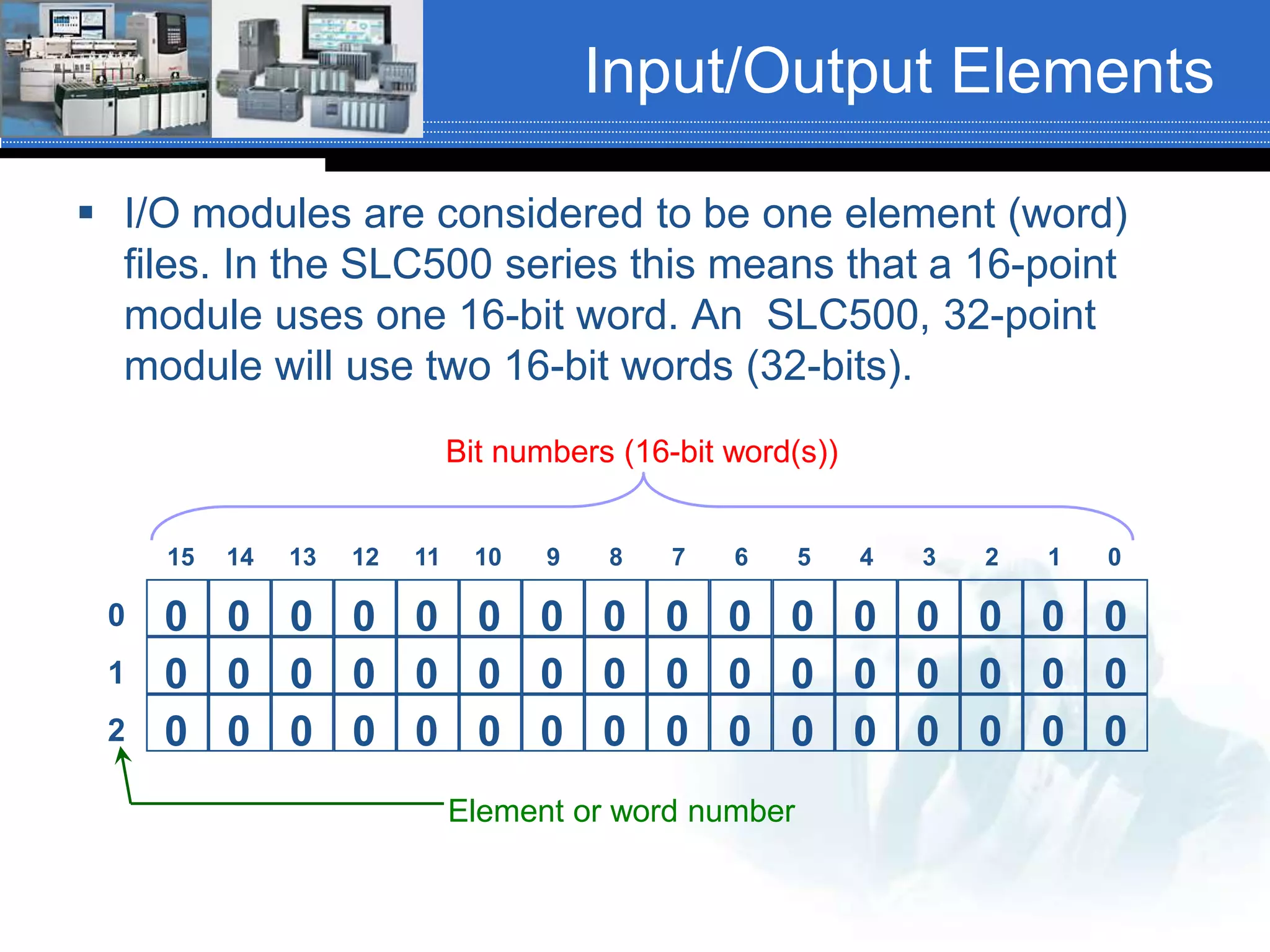
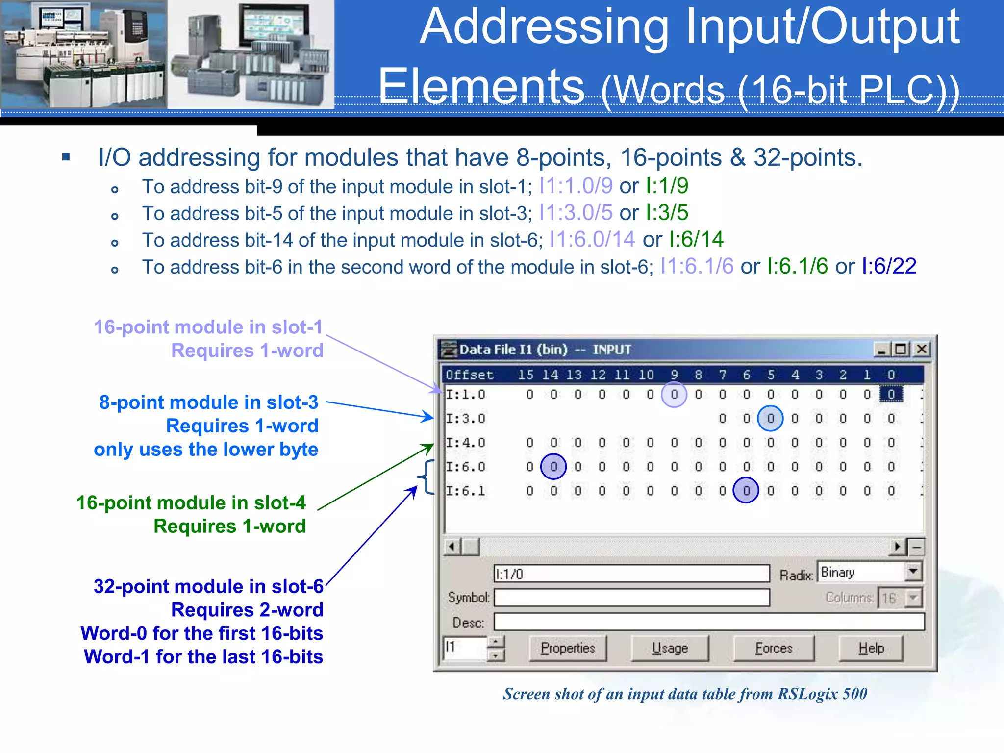
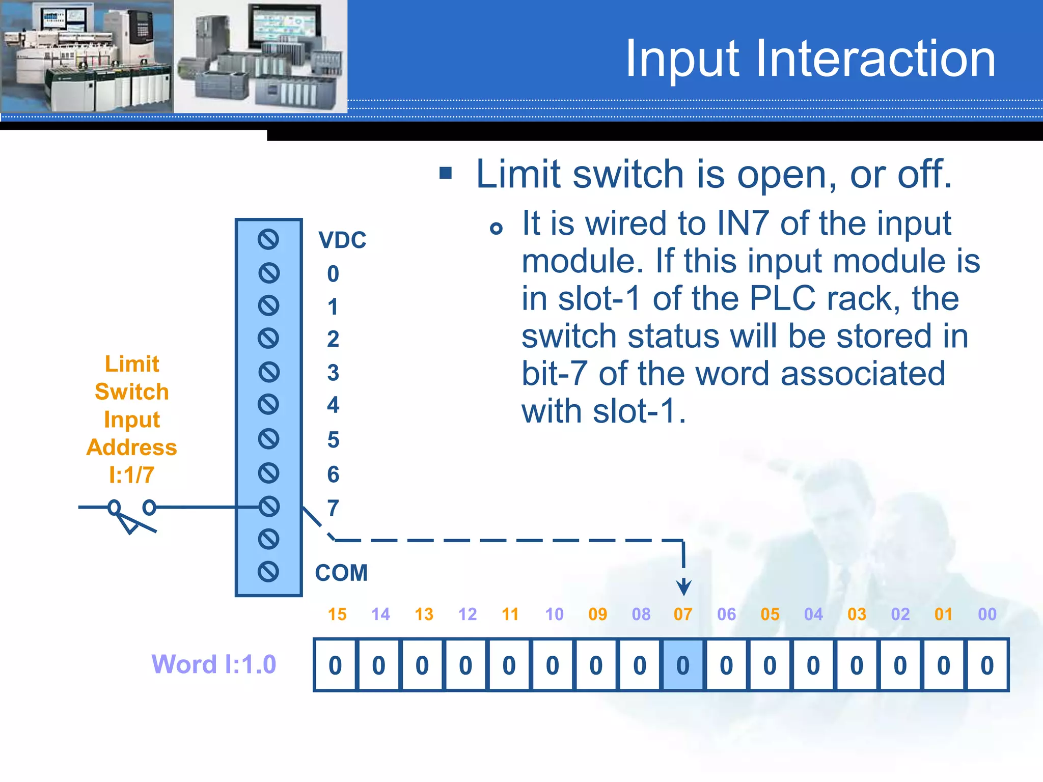
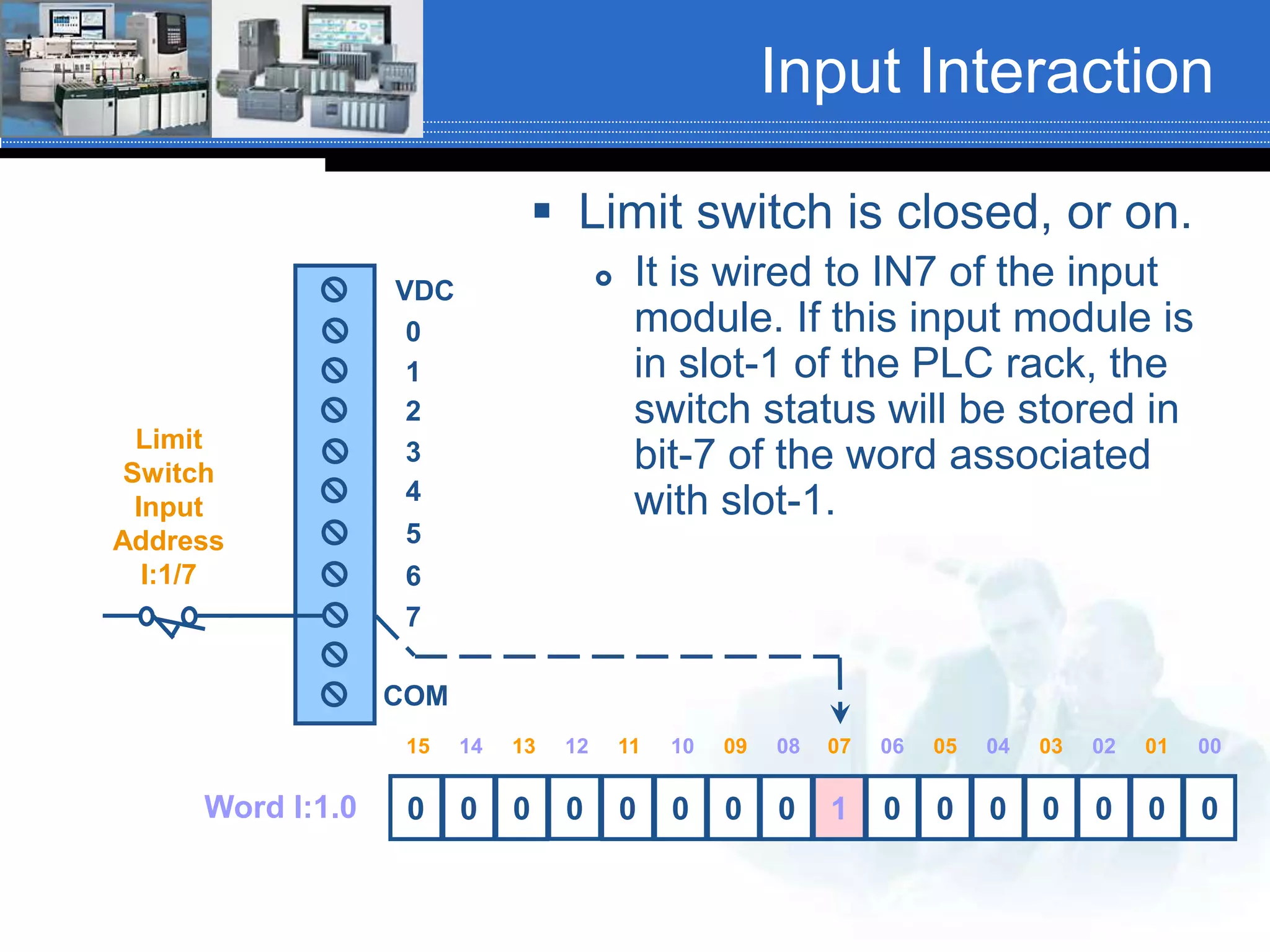
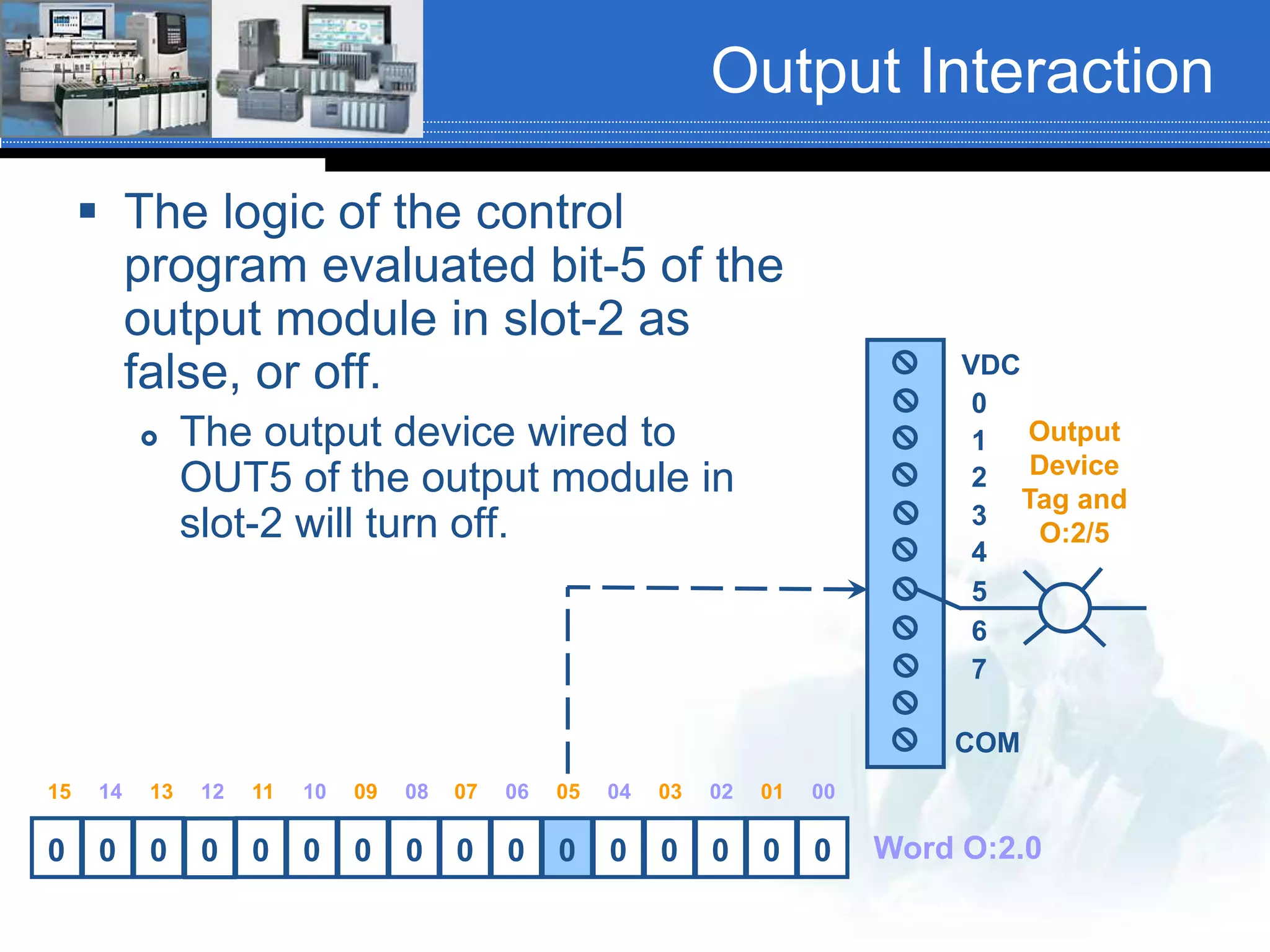
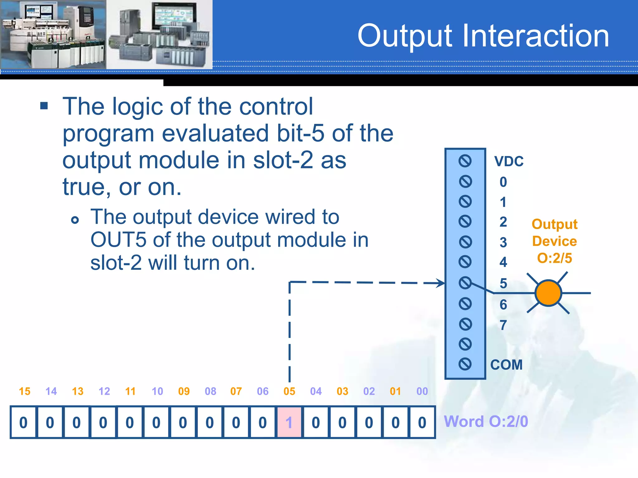
SlideShare a Scribd company logo
Chapter 03 Sect. 3-4, 3-5, 3-5-1,
3-5-3, 3-6, 3-6-2, 3-6-3, 3-7,
3-7-1, 3-9, 3-10
PLC/PAC Memory Structure and Addressing
Memory Structure &
Organization
 As mentioned previously, there are three
basic types of memory structures and
organizations:
 Address-based memory
 Tag-based memory
 Combination of Address/Tag-based memory
Rack-Based Memory
 Representation of
most rack/slot
address-based PLCs.
 Represented by a
two drawer file
cabinet.
 One drawer for data
files
 One drawer for
program files
James A. Rehg, Glenn J. Sartori, Programmable Logic Controllers, 2nd Edition, Pg. 85
Program Memory
 The user program
accounts for most of the
memory in a PLC system.
 Program files contain the
logic that controls the
machine operation. This
logic consists of
instructions that are
programmed in ladder
logic format.
James A. Rehg, Glenn J. Sartori, Programmable Logic Controllers, 2nd Edition, Pg. 85
Memory Addressing
 A memory address is a location within the PLC
memory where information is stored.
 The Allen Bradley SLC500 series PLC uses an
alpha numeric sequence separated by delimiters
that specifies the:
 Type of data (bit level or word level)
 Slot location of an I/O module in a rack when
addressing field I/O
 Word number in memory, (Word is also referred to as
an element)
 Input or output number for field I/O and bit number for
internal coils and contacts.
AB SLC500 Slot Locations
Slot 0 Slot 1 Slot 2 Slot 3 Slot 4 Slot 5 Slot 6
AB SLC500 I/O Address
Format
I1:4.0/4
File type
File number
File delimiter
Slot or element number
Word delimiter
Word number
Bit delimiter
Bit or terminal
number
States: Input module in slot 4 IN4
O0:5.0/13 – Output module, slot 5, OUT13
AB SLC500 I/O Address
Format
I1:4.0/4
File type
Required
File number
Only required when a
user defined file is
being specified.
File delimiter
Required
Slot or element number
Required
Word delimiter
Only required when
specifying a word number.
Word number
Only required if pointing to a
word other than word zero.
Defaults to word zero.
Bit delimiter
Only required when
addressing to “bit level”.
Bit or IN/OUT number
Only required when addressing to “bit
level”.
This address can be rewritten as: I:4/4
SLC500 Default File Types
File Type Identifier File Number
Output O 0
Input I 1
Status S 2
Bit B 3
Timer T 4
Counter C 5
Control R 6
Integer N 7
Floating Point * F 8
* Available in SLC-5/03 OS301, OS302 & SLC-5/04 OS400, OS401 &
SLC-5/05 processors
SLC500 User Defined File
Types
File Type Identifier File Number
Bit B 91 - 255
Timer T 91 - 255
Counter C 91 - 255
Control R 91 - 255
Integer N 91 - 255
Floating Point * F 91 - 255
String * St 91 – 255
ASCII * A 91 - 255
Special Note1 Computer Interface File (CIF)1 9
•Available in SLC-5/03 OS301, OS302 & SLC-5/04 OS400, OS401 & SLC-
5/05 processors
1 The only file that data can be xmitted/received to/from non-IP devices
Data Files in the Project
Window
RSLogix 500 Default Files
Input/Output Elements
 I/O modules are considered to be one element (word)
files. In the SLC500 series this means that a 16-point
module uses one 16-bit word. An SLC500, 32-point
module will use two 16-bit words (32-bits).
0 0 0 0 0 0 0 00 0 0 0 0 0 0 0
15 10 9 8 7 6 5 4 3 2 1 014 13 12 11
0 0 0 0 0 0 0 00 0 0 0 0 0 0 0
0 0 0 0 0 0 0 00 0 0 0 0 0 0 0
0
1
2
Bit numbers (16-bit word(s))
Element or word number
Addressing Input/Output
Elements (Words (16-bit PLC))
 I/O addressing for modules that have 8-points, 16-points & 32-points.
 To address bit-9 of the input module in slot-1; I1:1.0/9 or I:1/9
 To address bit-5 of the input module in slot-3; I1:3.0/5 or I:3/5
 To address bit-14 of the input module in slot-6; I1:6.0/14 or I:6/14
 To address bit-6 in the second word of the module in slot-6; I1:6.1/6 or I:6.1/6 or I:6/22
16-point module in slot-1
Requires 1-word
16-point module in slot-4
Requires 1-word
8-point module in slot-3
Requires 1-word
only uses the lower byte
32-point module in slot-6
Requires 2-word
Word-0 for the first 16-bits
Word-1 for the last 16-bits
Screen shot of an input data table from RSLogix 500
Bit File, File #3
 File #3 is the bit file and is designated with
the letter ‘B’.
 One application for the bit file is for internal
control relays where each bit can be a relay
coil.
 In the SLC500 the bit file contains 256, 16-bit
words for a total of 4,096 bits.
 Each bit, when used as a coil, can have an
unlimited number of normally open and/or
normally closed contacts programmed to it.
Addressing the Bit File
 The bit file is addressed using the same
address structure as the Input/Output file.
 The differences are:
 The letter used for the file designator will now be
the letter ‘B’
 There is no slot number. What was the slot
number, now becomes the word number within
the file.
 The following address references word 0, bit
0, of the default bit file.
B3:0/0 or B:0/0
Addressing the Bit File
 Addressing Bit 12 in word 255 of the
default bit file would be:
B3:255/12 or B:255/12
 Addressing Word 42, bit 7, of the user
defined bit file number 12 would be:
B12:42/7
In this example the file number is required
because it is a user defined file.
Input Interaction
 Limit switch is open, or off.
 It is wired to IN7 of the input
module. If this input module is
in slot-1 of the PLC rack, the
switch status will be stored in
bit-7 of the word associated
with slot-1.
0 0 0 0 0 0 0 0 0 0 0 0 0 0 0 0
VDC
2
4
5
6
3
1
0
7
COM
02040506 03 0107 0010121314 11 0915 08
Word I:1.0
Limit
Switch
Input
Address
I:1/7
Input Interaction
 Limit switch is closed, or on.
 It is wired to IN7 of the input
module. If this input module is
in slot-1 of the PLC rack, the
switch status will be stored in
bit-7 of the word associated
with slot-1.
0 0 0 0 0 0 0 0 1 0 0 0 0 0 0 0
VDC
2
4
5
6
3
1
0
7
COM
02040506 03 0107 0010121314 11 0915 08
Limit
Switch
Input
Address
I:1/7
Word I:1.0
Output Interaction
 The logic of the control
program evaluated bit-5 of the
output module in slot-2 as
false, or off.
 The output device wired to
OUT5 of the output module in
slot-2 will turn off.
0 0 0 0 0 0 0 0 0 0 0 0 0 0 0 0
VDC
2
4
5
6
3
1
0
7
COM
02040506 03 0107 0010121314 11 0915 08
Word O:2.0
Output
Device
Tag and
O:2/5
Output Interaction
 The logic of the control
program evaluated bit-5 of the
output module in slot-2 as
true, or on.
 The output device wired to
OUT5 of the output module in
slot-2 will turn on.
0 0 0 0 0 0 0 0 0 0 1 0 0 0 0 0
VDC
2
4
5
6
3
1
0
7
COM
02040506 03 0107 0010121314 11 0915 08
Output
Device
O:2/5
Word O:2/0
SLC500 Basic Bit Level
Instructions
Normally Open
Examine if Closed
XIC
Normally Closed
Examine if Open
XIO
Output Coil
Output Energize
OTE
Rung Comment
Instruction
Description
Address Symbol
Address
Shown split with
bit number at the
base of the
instruction
Bit number
Rung number
Default color scheme shown
Processor Scan
 The processor evaluates the program logic
similar to the way we would evaluate
electromechanical ladder logic:
 Top to bottom, left to right, one rung at-a-time.
 This process is called Processor Scan or
simply Scan.
Read Input
Device Status
Solve the control program
logic based upon the
status of the input devices
Update the
status of
the output
devices
Housekeeping
and
communications
Scan Cycle
Read input
status
Solve the control
program and turn
internal coils on/off
Update the
outputs
Housekeeping
and
Communications
Other One Element Files
(16-bit PLC)
 The input and output files are not the only 1-element (1-word) files.
The following files are also 1-element (1-word) files:
 Status (file-2) Number of words in the file depends upon the processor
type
 Bit (file-3) 256, 16-bit words are available in each bit file
 Integer (file-7) 256, 16-bit words are available in each integer file
0 0 0 0 0 0 0 00 0 0 0 0 0 0 0
15 10 9 8 7 6 5 4 3 2 1 014 13 12 11
0 0 0 0 0 0 0 00 0 0 0 0 0 0 0
0 0 0 0 0 0 0 00 0 0 0 0 0 0 0
0
1
2
Bit numbers
Element or word number
Three or more Element
Files (16-bit PLC)
 Some file types in the Allen Bradley SLC500 series PLC
require more than 1-word per instruction.
 Timers, Counters and Control instructions are such files.
Each timer, counter or Control instruction requires 3-
words.
0 0 0 0 0 0 0 00 0 0 0 0 0 0 0
15 10 9 8 7 6 5 4 3 2 1 014 13 12 11
0
1
2
Element or word number. Word-0 will contain instruction
status bits. Values stored in words-1 & 2 will depend upon
the file type being addressed.
Bit numbers

More Related Content

What's hot

Embedded c program and programming structure for beginners
Embedded c program and programming structure for beginnersEmbedded c program and programming structure for beginners
Embedded c program and programming structure for beginners
Kamesh Mtec
 
8080 8085 assembly language_programming manual programando
8080 8085 assembly  language_programming manual programando 8080 8085 assembly  language_programming manual programando
8080 8085 assembly language_programming manual programando
Universidad de Tarapaca
 
microprocessor
 microprocessor microprocessor
microprocessor
ATTO RATHORE
 
Sp chap2
Sp chap2Sp chap2
Mp lab manual
Mp lab manualMp lab manual
Mp lab manual
Pradeep Kumar
 
Lec 12-15 mips instruction set processor
Lec 12-15 mips instruction set processorLec 12-15 mips instruction set processor
Lec 12-15 mips instruction set processor
Mayank Roy
 
microprocessor
   microprocessor   microprocessor
microprocessor
ATTO RATHORE
 
Register transfer and micro-operation
Register transfer and micro-operationRegister transfer and micro-operation
Register transfer and micro-operation
Nikhil Pandit
 
sistem mikroprosessor 2
sistem mikroprosessor 2sistem mikroprosessor 2
sistem mikroprosessor 2
yasir_cesc
 
Microcontrollers 80 Marks Sample Question Paper
Microcontrollers   80 Marks Sample Question PaperMicrocontrollers   80 Marks Sample Question Paper
Microcontrollers 80 Marks Sample Question Paper
prathik
 
DMA controller intel 8257
DMA controller intel 8257DMA controller intel 8257
DMA controller intel 8257
Daniel Ilunga
 
Assembly Language Programming Of 8085
Assembly Language Programming Of 8085Assembly Language Programming Of 8085
Assembly Language Programming Of 8085
techbed
 
flag register of 8086
flag register of 8086flag register of 8086
flag register of 8086
asrithak
 
Central processor organization
Central processor organizationCentral processor organization
Central processor organization
Prof. Dr. K. Adisesha
 
central processing unit and pipeline
central processing unit and pipelinecentral processing unit and pipeline
central processing unit and pipeline
Rai University
 
Stack and subroutine
Stack and subroutineStack and subroutine
Stack and subroutine
Ashim Saha
 
03 shift registers_and_more_data_manipulation_sp15
03 shift registers_and_more_data_manipulation_sp1503 shift registers_and_more_data_manipulation_sp15
03 shift registers_and_more_data_manipulation_sp15
John Todora
 
Hardware interfacing basics using AVR
Hardware interfacing basics using AVRHardware interfacing basics using AVR
Hardware interfacing basics using AVR
Mohamed Abdallah
 
Various type of register
Various type of registerVarious type of register
Various type of register
Muhammad Taqi Hassan Bukhari
 
Flagsregistor
Flagsregistor Flagsregistor
Flagsregistor
maamir farooq
 

What's hot (20)

Embedded c program and programming structure for beginners
Embedded c program and programming structure for beginnersEmbedded c program and programming structure for beginners
Embedded c program and programming structure for beginners
 
8080 8085 assembly language_programming manual programando
8080 8085 assembly  language_programming manual programando 8080 8085 assembly  language_programming manual programando
8080 8085 assembly language_programming manual programando
 
microprocessor
 microprocessor microprocessor
microprocessor
 
Sp chap2
Sp chap2Sp chap2
Sp chap2
 
Mp lab manual
Mp lab manualMp lab manual
Mp lab manual
 
Lec 12-15 mips instruction set processor
Lec 12-15 mips instruction set processorLec 12-15 mips instruction set processor
Lec 12-15 mips instruction set processor
 
microprocessor
   microprocessor   microprocessor
microprocessor
 
Register transfer and micro-operation
Register transfer and micro-operationRegister transfer and micro-operation
Register transfer and micro-operation
 
sistem mikroprosessor 2
sistem mikroprosessor 2sistem mikroprosessor 2
sistem mikroprosessor 2
 
Microcontrollers 80 Marks Sample Question Paper
Microcontrollers   80 Marks Sample Question PaperMicrocontrollers   80 Marks Sample Question Paper
Microcontrollers 80 Marks Sample Question Paper
 
DMA controller intel 8257
DMA controller intel 8257DMA controller intel 8257
DMA controller intel 8257
 
Assembly Language Programming Of 8085
Assembly Language Programming Of 8085Assembly Language Programming Of 8085
Assembly Language Programming Of 8085
 
flag register of 8086
flag register of 8086flag register of 8086
flag register of 8086
 
Central processor organization
Central processor organizationCentral processor organization
Central processor organization
 
central processing unit and pipeline
central processing unit and pipelinecentral processing unit and pipeline
central processing unit and pipeline
 
Stack and subroutine
Stack and subroutineStack and subroutine
Stack and subroutine
 
03 shift registers_and_more_data_manipulation_sp15
03 shift registers_and_more_data_manipulation_sp1503 shift registers_and_more_data_manipulation_sp15
03 shift registers_and_more_data_manipulation_sp15
 
Hardware interfacing basics using AVR
Hardware interfacing basics using AVRHardware interfacing basics using AVR
Hardware interfacing basics using AVR
 
Various type of register
Various type of registerVarious type of register
Various type of register
 
Flagsregistor
Flagsregistor Flagsregistor
Flagsregistor
 

Viewers also liked

05 analog control_sp15
05 analog control_sp1505 analog control_sp15
05 analog control_sp15
John Todora
 
12 chapter06 math_instructions_fa14
12 chapter06 math_instructions_fa1412 chapter06 math_instructions_fa14
12 chapter06 math_instructions_fa14
John Todora
 
13 chap07 and_08_comparison_subs_force_fa14
13 chap07 and_08_comparison_subs_force_fa1413 chap07 and_08_comparison_subs_force_fa14
13 chap07 and_08_comparison_subs_force_fa14
John Todora
 
04 chapter04 specification_forms
04 chapter04 specification_forms04 chapter04 specification_forms
04 chapter04 specification_forms
John Todora
 
11 chapter06 slc_int_float_mov_mvm_fa14
11 chapter06 slc_int_float_mov_mvm_fa1411 chapter06 slc_int_float_mov_mvm_fa14
11 chapter06 slc_int_float_mov_mvm_fa14
John Todora
 
00 chapter07 and_08_conversion_subroutines_force_sp13
00 chapter07 and_08_conversion_subroutines_force_sp1300 chapter07 and_08_conversion_subroutines_force_sp13
00 chapter07 and_08_conversion_subroutines_force_sp13
John Todora
 
01 indirect indexed_addressing_and_arrays_sp15
01 indirect indexed_addressing_and_arrays_sp1501 indirect indexed_addressing_and_arrays_sp15
01 indirect indexed_addressing_and_arrays_sp15
John Todora
 
10 chapter05 counters_fa14
10 chapter05 counters_fa1410 chapter05 counters_fa14
10 chapter05 counters_fa14
John Todora
 
System programming and implementation
System programming and implementationSystem programming and implementation
System programming and implementation
John Todora
 
01 introduction to_plc-pac_rev01_fa16
01 introduction to_plc-pac_rev01_fa1601 introduction to_plc-pac_rev01_fa16
01 introduction to_plc-pac_rev01_fa16
John Todora
 
04 chapter03 02_numbers_systems_student_version_fa16
04 chapter03 02_numbers_systems_student_version_fa1604 chapter03 02_numbers_systems_student_version_fa16
04 chapter03 02_numbers_systems_student_version_fa16
John Todora
 
03 chapter03 lists_indexes_databases
03 chapter03 lists_indexes_databases03 chapter03 lists_indexes_databases
03 chapter03 lists_indexes_databases
John Todora
 
Lab02 lead in
Lab02 lead inLab02 lead in
Lab02 lead in
John Todora
 
Comparison instructions, AB, Siemens and AB CCW
Comparison instructions, AB, Siemens and AB CCWComparison instructions, AB, Siemens and AB CCW
Comparison instructions, AB, Siemens and AB CCW
John Todora
 
07 chapter07 loop_diagrams
07 chapter07 loop_diagrams07 chapter07 loop_diagrams
07 chapter07 loop_diagrams
John Todora
 
06 chapter06 binary_logic_systems_Rev02
06 chapter06 binary_logic_systems_Rev0206 chapter06 binary_logic_systems_Rev02
06 chapter06 binary_logic_systems_Rev02
John Todora
 
EMEC130 P&ID Symbol Primer
EMEC130 P&ID Symbol PrimerEMEC130 P&ID Symbol Primer
EMEC130 P&ID Symbol Primer
John Todora
 
Control Systems Basics
Control Systems BasicsControl Systems Basics
Control Systems Basics
John Todora
 
Lab02 review
Lab02 reviewLab02 review
Lab02 review
John Todora
 

Viewers also liked (19)

05 analog control_sp15
05 analog control_sp1505 analog control_sp15
05 analog control_sp15
 
12 chapter06 math_instructions_fa14
12 chapter06 math_instructions_fa1412 chapter06 math_instructions_fa14
12 chapter06 math_instructions_fa14
 
13 chap07 and_08_comparison_subs_force_fa14
13 chap07 and_08_comparison_subs_force_fa1413 chap07 and_08_comparison_subs_force_fa14
13 chap07 and_08_comparison_subs_force_fa14
 
04 chapter04 specification_forms
04 chapter04 specification_forms04 chapter04 specification_forms
04 chapter04 specification_forms
 
11 chapter06 slc_int_float_mov_mvm_fa14
11 chapter06 slc_int_float_mov_mvm_fa1411 chapter06 slc_int_float_mov_mvm_fa14
11 chapter06 slc_int_float_mov_mvm_fa14
 
00 chapter07 and_08_conversion_subroutines_force_sp13
00 chapter07 and_08_conversion_subroutines_force_sp1300 chapter07 and_08_conversion_subroutines_force_sp13
00 chapter07 and_08_conversion_subroutines_force_sp13
 
01 indirect indexed_addressing_and_arrays_sp15
01 indirect indexed_addressing_and_arrays_sp1501 indirect indexed_addressing_and_arrays_sp15
01 indirect indexed_addressing_and_arrays_sp15
 
10 chapter05 counters_fa14
10 chapter05 counters_fa1410 chapter05 counters_fa14
10 chapter05 counters_fa14
 
System programming and implementation
System programming and implementationSystem programming and implementation
System programming and implementation
 
01 introduction to_plc-pac_rev01_fa16
01 introduction to_plc-pac_rev01_fa1601 introduction to_plc-pac_rev01_fa16
01 introduction to_plc-pac_rev01_fa16
 
04 chapter03 02_numbers_systems_student_version_fa16
04 chapter03 02_numbers_systems_student_version_fa1604 chapter03 02_numbers_systems_student_version_fa16
04 chapter03 02_numbers_systems_student_version_fa16
 
03 chapter03 lists_indexes_databases
03 chapter03 lists_indexes_databases03 chapter03 lists_indexes_databases
03 chapter03 lists_indexes_databases
 
Lab02 lead in
Lab02 lead inLab02 lead in
Lab02 lead in
 
Comparison instructions, AB, Siemens and AB CCW
Comparison instructions, AB, Siemens and AB CCWComparison instructions, AB, Siemens and AB CCW
Comparison instructions, AB, Siemens and AB CCW
 
07 chapter07 loop_diagrams
07 chapter07 loop_diagrams07 chapter07 loop_diagrams
07 chapter07 loop_diagrams
 
06 chapter06 binary_logic_systems_Rev02
06 chapter06 binary_logic_systems_Rev0206 chapter06 binary_logic_systems_Rev02
06 chapter06 binary_logic_systems_Rev02
 
EMEC130 P&ID Symbol Primer
EMEC130 P&ID Symbol PrimerEMEC130 P&ID Symbol Primer
EMEC130 P&ID Symbol Primer
 
Control Systems Basics
Control Systems BasicsControl Systems Basics
Control Systems Basics
 
Lab02 review
Lab02 reviewLab02 review
Lab02 review
 

Similar to 05 chapter03 03_memory_structure_slc500_fa16

Micro controller
Micro controllerMicro controller
Micro controller
Dr. Ashok Kumar K
 
8051 microcontroller
8051 microcontroller 8051 microcontroller
8051 microcontroller
nitugatkal
 
PLC Training Intro
PLC Training IntroPLC Training Intro
PLC Training Intro
Business Industrial Network
 
EMBEDDED SYSTEMS AND IOT lab manual for enginnering students
EMBEDDED SYSTEMS AND IOT lab manual for enginnering studentsEMBEDDED SYSTEMS AND IOT lab manual for enginnering students
EMBEDDED SYSTEMS AND IOT lab manual for enginnering students
eceprinter6
 
Architecture of 8051
Architecture of 8051Architecture of 8051
Architecture of 8051
OGAGA OTOBOR
 
Chapter7_InputOutputStorageSystems.pptx
Chapter7_InputOutputStorageSystems.pptxChapter7_InputOutputStorageSystems.pptx
Chapter7_InputOutputStorageSystems.pptx
JanethMedina31
 
Embedded systems ppt i
Embedded systems ppt iEmbedded systems ppt i
Embedded systems ppt i
anishgoel
 
8051 Microcontroller_module_4.1.pptx
8051 Microcontroller_module_4.1.pptx8051 Microcontroller_module_4.1.pptx
8051 Microcontroller_module_4.1.pptx
ARYAKUMARNIRAV
 
Architecture of the Intel 8051 Microcontroller
Architecture of the Intel 8051 MicrocontrollerArchitecture of the Intel 8051 Microcontroller
Architecture of the Intel 8051 Microcontroller
Sudhanshu Janwadkar
 
Basics of plc_programming
Basics of plc_programmingBasics of plc_programming
Basics of plc_programming
hamza239523
 
Basics of plc programming
Basics of plc programmingBasics of plc programming
Basics of plc programming
Sergio Barrios
 
Microcontroller (8051) by K. Vijay Kumar
Microcontroller (8051) by K. Vijay KumarMicrocontroller (8051) by K. Vijay Kumar
Microcontroller (8051) by K. Vijay Kumar
Vijay Kumar
 
MICROCONTROLLER - INTEL 8051
MICROCONTROLLER - INTEL 8051MICROCONTROLLER - INTEL 8051
MICROCONTROLLER - INTEL 8051
DEPARTMENT OF PHYSICS
 
unit-2.pptx
unit-2.pptxunit-2.pptx
unit-2.pptx
KanchanThory
 
8051 microcontroller by K. Vijay Kumar
8051 microcontroller by K. Vijay Kumar8051 microcontroller by K. Vijay Kumar
8051 microcontroller by K. Vijay Kumar
Vijay Kumar
 
Microcontroller 8051
Microcontroller 8051Microcontroller 8051
Microcontroller 8051
Sadiq Rahim
 
Microcontroller 8051 basics (part I)
Microcontroller 8051 basics (part I)Microcontroller 8051 basics (part I)
Microcontroller 8051 basics (part I)
Nilesh Bhaskarrao Bahadure
 
Microprocessorlabmanual ee0310
Microprocessorlabmanual ee0310Microprocessorlabmanual ee0310
Microprocessorlabmanual ee0310
DHEERAJ DHAKAR
 
SYBSC IT SEM IV EMBEDDED SYSTEMS UNIT III The 8051 Microcontrollers
SYBSC IT SEM IV EMBEDDED SYSTEMS UNIT III  The 8051 MicrocontrollersSYBSC IT SEM IV EMBEDDED SYSTEMS UNIT III  The 8051 Microcontrollers
SYBSC IT SEM IV EMBEDDED SYSTEMS UNIT III The 8051 Microcontrollers
Arti Parab Academics
 
Evaluation of OpenFlow in RB750GL
Evaluation of OpenFlow in RB750GLEvaluation of OpenFlow in RB750GL
Evaluation of OpenFlow in RB750GL
Toshiki Tsuboi
 

Similar to 05 chapter03 03_memory_structure_slc500_fa16 (20)

Micro controller
Micro controllerMicro controller
Micro controller
 
8051 microcontroller
8051 microcontroller 8051 microcontroller
8051 microcontroller
 
PLC Training Intro
PLC Training IntroPLC Training Intro
PLC Training Intro
 
EMBEDDED SYSTEMS AND IOT lab manual for enginnering students
EMBEDDED SYSTEMS AND IOT lab manual for enginnering studentsEMBEDDED SYSTEMS AND IOT lab manual for enginnering students
EMBEDDED SYSTEMS AND IOT lab manual for enginnering students
 
Architecture of 8051
Architecture of 8051Architecture of 8051
Architecture of 8051
 
Chapter7_InputOutputStorageSystems.pptx
Chapter7_InputOutputStorageSystems.pptxChapter7_InputOutputStorageSystems.pptx
Chapter7_InputOutputStorageSystems.pptx
 
Embedded systems ppt i
Embedded systems ppt iEmbedded systems ppt i
Embedded systems ppt i
 
8051 Microcontroller_module_4.1.pptx
8051 Microcontroller_module_4.1.pptx8051 Microcontroller_module_4.1.pptx
8051 Microcontroller_module_4.1.pptx
 
Architecture of the Intel 8051 Microcontroller
Architecture of the Intel 8051 MicrocontrollerArchitecture of the Intel 8051 Microcontroller
Architecture of the Intel 8051 Microcontroller
 
Basics of plc_programming
Basics of plc_programmingBasics of plc_programming
Basics of plc_programming
 
Basics of plc programming
Basics of plc programmingBasics of plc programming
Basics of plc programming
 
Microcontroller (8051) by K. Vijay Kumar
Microcontroller (8051) by K. Vijay KumarMicrocontroller (8051) by K. Vijay Kumar
Microcontroller (8051) by K. Vijay Kumar
 
MICROCONTROLLER - INTEL 8051
MICROCONTROLLER - INTEL 8051MICROCONTROLLER - INTEL 8051
MICROCONTROLLER - INTEL 8051
 
unit-2.pptx
unit-2.pptxunit-2.pptx
unit-2.pptx
 
8051 microcontroller by K. Vijay Kumar
8051 microcontroller by K. Vijay Kumar8051 microcontroller by K. Vijay Kumar
8051 microcontroller by K. Vijay Kumar
 
Microcontroller 8051
Microcontroller 8051Microcontroller 8051
Microcontroller 8051
 
Microcontroller 8051 basics (part I)
Microcontroller 8051 basics (part I)Microcontroller 8051 basics (part I)
Microcontroller 8051 basics (part I)
 
Microprocessorlabmanual ee0310
Microprocessorlabmanual ee0310Microprocessorlabmanual ee0310
Microprocessorlabmanual ee0310
 
SYBSC IT SEM IV EMBEDDED SYSTEMS UNIT III The 8051 Microcontrollers
SYBSC IT SEM IV EMBEDDED SYSTEMS UNIT III  The 8051 MicrocontrollersSYBSC IT SEM IV EMBEDDED SYSTEMS UNIT III  The 8051 Microcontrollers
SYBSC IT SEM IV EMBEDDED SYSTEMS UNIT III The 8051 Microcontrollers
 
Evaluation of OpenFlow in RB750GL
Evaluation of OpenFlow in RB750GLEvaluation of OpenFlow in RB750GL
Evaluation of OpenFlow in RB750GL
 

More from John Todora

04 scaling analog_datal_sp17
04 scaling analog_datal_sp1704 scaling analog_datal_sp17
04 scaling analog_datal_sp17
John Todora
 
03 analog control_sp17
03 analog control_sp1703 analog control_sp17
03 analog control_sp17
John Todora
 
01 control logix_arrays_sp17
01 control logix_arrays_sp1701 control logix_arrays_sp17
01 control logix_arrays_sp17
John Todora
 
Subroutines rev01 fa16
Subroutines rev01 fa16Subroutines rev01 fa16
Subroutines rev01 fa16
John Todora
 
Math cl ccw_siemens_rev01_fa16
Math cl ccw_siemens_rev01_fa16Math cl ccw_siemens_rev01_fa16
Math cl ccw_siemens_rev01_fa16
John Todora
 
ControlLogix Counters FA16
ControlLogix Counters FA16ControlLogix Counters FA16
ControlLogix Counters FA16
John Todora
 
ControlLogix Timers FA16
ControlLogix Timers FA16ControlLogix Timers FA16
ControlLogix Timers FA16
John Todora
 
02 chapter02 fa16
02 chapter02 fa1602 chapter02 fa16
02 chapter02 fa16
John Todora
 
02 chapter02 p&ids_and_symbols_split_animations
02 chapter02 p&ids_and_symbols_split_animations02 chapter02 p&ids_and_symbols_split_animations
02 chapter02 p&ids_and_symbols_split_animations
John Todora
 
01 chapter01 process_flow_diagram
01 chapter01 process_flow_diagram01 chapter01 process_flow_diagram
01 chapter01 process_flow_diagram
John Todora
 
00 introduction
00 introduction00 introduction
00 introduction
John Todora
 
01 overview of_industrial_automation_sp15
01 overview of_industrial_automation_sp1501 overview of_industrial_automation_sp15
01 overview of_industrial_automation_sp15
John Todora
 

More from John Todora (12)

04 scaling analog_datal_sp17
04 scaling analog_datal_sp1704 scaling analog_datal_sp17
04 scaling analog_datal_sp17
 
03 analog control_sp17
03 analog control_sp1703 analog control_sp17
03 analog control_sp17
 
01 control logix_arrays_sp17
01 control logix_arrays_sp1701 control logix_arrays_sp17
01 control logix_arrays_sp17
 
Subroutines rev01 fa16
Subroutines rev01 fa16Subroutines rev01 fa16
Subroutines rev01 fa16
 
Math cl ccw_siemens_rev01_fa16
Math cl ccw_siemens_rev01_fa16Math cl ccw_siemens_rev01_fa16
Math cl ccw_siemens_rev01_fa16
 
ControlLogix Counters FA16
ControlLogix Counters FA16ControlLogix Counters FA16
ControlLogix Counters FA16
 
ControlLogix Timers FA16
ControlLogix Timers FA16ControlLogix Timers FA16
ControlLogix Timers FA16
 
02 chapter02 fa16
02 chapter02 fa1602 chapter02 fa16
02 chapter02 fa16
 
02 chapter02 p&ids_and_symbols_split_animations
02 chapter02 p&ids_and_symbols_split_animations02 chapter02 p&ids_and_symbols_split_animations
02 chapter02 p&ids_and_symbols_split_animations
 
01 chapter01 process_flow_diagram
01 chapter01 process_flow_diagram01 chapter01 process_flow_diagram
01 chapter01 process_flow_diagram
 
00 introduction
00 introduction00 introduction
00 introduction
 
01 overview of_industrial_automation_sp15
01 overview of_industrial_automation_sp1501 overview of_industrial_automation_sp15
01 overview of_industrial_automation_sp15
 

Recently uploaded

Transformers design and coooling methods
Transformers design and coooling methodsTransformers design and coooling methods
Transformers design and coooling methods
Roger Rozario
 
一比一原版(osu毕业证书)美国俄勒冈州立大学毕业证如何办理
一比一原版(osu毕业证书)美国俄勒冈州立大学毕业证如何办理一比一原版(osu毕业证书)美国俄勒冈州立大学毕业证如何办理
一比一原版(osu毕业证书)美国俄勒冈州立大学毕业证如何办理
upoux
 
Accident detection system project report.pdf
Accident detection system project report.pdfAccident detection system project report.pdf
Accident detection system project report.pdf
Kamal Acharya
 
DESIGN AND MANUFACTURE OF CEILING BOARD USING SAWDUST AND WASTE CARTON MATERI...
DESIGN AND MANUFACTURE OF CEILING BOARD USING SAWDUST AND WASTE CARTON MATERI...DESIGN AND MANUFACTURE OF CEILING BOARD USING SAWDUST AND WASTE CARTON MATERI...
DESIGN AND MANUFACTURE OF CEILING BOARD USING SAWDUST AND WASTE CARTON MATERI...
OKORIE1
 
Digital Twins Computer Networking Paper Presentation.pptx
Digital Twins Computer Networking Paper Presentation.pptxDigital Twins Computer Networking Paper Presentation.pptx
Digital Twins Computer Networking Paper Presentation.pptx
aryanpankaj78
 
原版制作(Humboldt毕业证书)柏林大学毕业证学位证一模一样
原版制作(Humboldt毕业证书)柏林大学毕业证学位证一模一样原版制作(Humboldt毕业证书)柏林大学毕业证学位证一模一样
原版制作(Humboldt毕业证书)柏林大学毕业证学位证一模一样
ydzowc
 
Ericsson LTE Throughput Troubleshooting Techniques.ppt
Ericsson LTE Throughput Troubleshooting Techniques.pptEricsson LTE Throughput Troubleshooting Techniques.ppt
Ericsson LTE Throughput Troubleshooting Techniques.ppt
wafawafa52
 
Introduction to Computer Networks & OSI MODEL.ppt
Introduction to Computer Networks & OSI MODEL.pptIntroduction to Computer Networks & OSI MODEL.ppt
Introduction to Computer Networks & OSI MODEL.ppt
Dwarkadas J Sanghvi College of Engineering
 
4. Mosca vol I -Fisica-Tipler-5ta-Edicion-Vol-1.pdf
4. Mosca vol I -Fisica-Tipler-5ta-Edicion-Vol-1.pdf4. Mosca vol I -Fisica-Tipler-5ta-Edicion-Vol-1.pdf
4. Mosca vol I -Fisica-Tipler-5ta-Edicion-Vol-1.pdf
Gino153088
 
Mechanical Engineering on AAI Summer Training Report-003.pdf
Mechanical Engineering on AAI Summer Training Report-003.pdfMechanical Engineering on AAI Summer Training Report-003.pdf
Mechanical Engineering on AAI Summer Training Report-003.pdf
21UME003TUSHARDEB
 
5G Radio Network Througput Problem Analysis HCIA.pdf
5G Radio Network Througput Problem Analysis HCIA.pdf5G Radio Network Througput Problem Analysis HCIA.pdf
5G Radio Network Througput Problem Analysis HCIA.pdf
AlvianRamadhani5
 
DEEP LEARNING FOR SMART GRID INTRUSION DETECTION: A HYBRID CNN-LSTM-BASED MODEL
DEEP LEARNING FOR SMART GRID INTRUSION DETECTION: A HYBRID CNN-LSTM-BASED MODELDEEP LEARNING FOR SMART GRID INTRUSION DETECTION: A HYBRID CNN-LSTM-BASED MODEL
DEEP LEARNING FOR SMART GRID INTRUSION DETECTION: A HYBRID CNN-LSTM-BASED MODEL
ijaia
 
一比一原版(CalArts毕业证)加利福尼亚艺术学院毕业证如何办理
一比一原版(CalArts毕业证)加利福尼亚艺术学院毕业证如何办理一比一原版(CalArts毕业证)加利福尼亚艺术学院毕业证如何办理
一比一原版(CalArts毕业证)加利福尼亚艺术学院毕业证如何办理
ecqow
 
smart pill dispenser is designed to improve medication adherence and safety f...
smart pill dispenser is designed to improve medication adherence and safety f...smart pill dispenser is designed to improve medication adherence and safety f...
smart pill dispenser is designed to improve medication adherence and safety f...
um7474492
 
A high-Speed Communication System is based on the Design of a Bi-NoC Router, ...
A high-Speed Communication System is based on the Design of a Bi-NoC Router, ...A high-Speed Communication System is based on the Design of a Bi-NoC Router, ...
A high-Speed Communication System is based on the Design of a Bi-NoC Router, ...
DharmaBanothu
 
Zener Diode and its V-I Characteristics and Applications
Zener Diode and its V-I Characteristics and ApplicationsZener Diode and its V-I Characteristics and Applications
Zener Diode and its V-I Characteristics and Applications
Shiny Christobel
 
Blood finder application project report (1).pdf
Blood finder application project report (1).pdfBlood finder application project report (1).pdf
Blood finder application project report (1).pdf
Kamal Acharya
 
1FIDIC-CONSTRUCTION-CONTRACT-2ND-ED-2017-RED-BOOK.pdf
1FIDIC-CONSTRUCTION-CONTRACT-2ND-ED-2017-RED-BOOK.pdf1FIDIC-CONSTRUCTION-CONTRACT-2ND-ED-2017-RED-BOOK.pdf
1FIDIC-CONSTRUCTION-CONTRACT-2ND-ED-2017-RED-BOOK.pdf
MadhavJungKarki
 
This study Examines the Effectiveness of Talent Procurement through the Imple...
This study Examines the Effectiveness of Talent Procurement through the Imple...This study Examines the Effectiveness of Talent Procurement through the Imple...
This study Examines the Effectiveness of Talent Procurement through the Imple...
DharmaBanothu
 
UNIT 4 LINEAR INTEGRATED CIRCUITS-DIGITAL ICS
UNIT 4 LINEAR INTEGRATED CIRCUITS-DIGITAL ICSUNIT 4 LINEAR INTEGRATED CIRCUITS-DIGITAL ICS
UNIT 4 LINEAR INTEGRATED CIRCUITS-DIGITAL ICS
vmspraneeth
 

Recently uploaded (20)

Transformers design and coooling methods
Transformers design and coooling methodsTransformers design and coooling methods
Transformers design and coooling methods
 
一比一原版(osu毕业证书)美国俄勒冈州立大学毕业证如何办理
一比一原版(osu毕业证书)美国俄勒冈州立大学毕业证如何办理一比一原版(osu毕业证书)美国俄勒冈州立大学毕业证如何办理
一比一原版(osu毕业证书)美国俄勒冈州立大学毕业证如何办理
 
Accident detection system project report.pdf
Accident detection system project report.pdfAccident detection system project report.pdf
Accident detection system project report.pdf
 
DESIGN AND MANUFACTURE OF CEILING BOARD USING SAWDUST AND WASTE CARTON MATERI...
DESIGN AND MANUFACTURE OF CEILING BOARD USING SAWDUST AND WASTE CARTON MATERI...DESIGN AND MANUFACTURE OF CEILING BOARD USING SAWDUST AND WASTE CARTON MATERI...
DESIGN AND MANUFACTURE OF CEILING BOARD USING SAWDUST AND WASTE CARTON MATERI...
 
Digital Twins Computer Networking Paper Presentation.pptx
Digital Twins Computer Networking Paper Presentation.pptxDigital Twins Computer Networking Paper Presentation.pptx
Digital Twins Computer Networking Paper Presentation.pptx
 
原版制作(Humboldt毕业证书)柏林大学毕业证学位证一模一样
原版制作(Humboldt毕业证书)柏林大学毕业证学位证一模一样原版制作(Humboldt毕业证书)柏林大学毕业证学位证一模一样
原版制作(Humboldt毕业证书)柏林大学毕业证学位证一模一样
 
Ericsson LTE Throughput Troubleshooting Techniques.ppt
Ericsson LTE Throughput Troubleshooting Techniques.pptEricsson LTE Throughput Troubleshooting Techniques.ppt
Ericsson LTE Throughput Troubleshooting Techniques.ppt
 
Introduction to Computer Networks & OSI MODEL.ppt
Introduction to Computer Networks & OSI MODEL.pptIntroduction to Computer Networks & OSI MODEL.ppt
Introduction to Computer Networks & OSI MODEL.ppt
 
4. Mosca vol I -Fisica-Tipler-5ta-Edicion-Vol-1.pdf
4. Mosca vol I -Fisica-Tipler-5ta-Edicion-Vol-1.pdf4. Mosca vol I -Fisica-Tipler-5ta-Edicion-Vol-1.pdf
4. Mosca vol I -Fisica-Tipler-5ta-Edicion-Vol-1.pdf
 
Mechanical Engineering on AAI Summer Training Report-003.pdf
Mechanical Engineering on AAI Summer Training Report-003.pdfMechanical Engineering on AAI Summer Training Report-003.pdf
Mechanical Engineering on AAI Summer Training Report-003.pdf
 
5G Radio Network Througput Problem Analysis HCIA.pdf
5G Radio Network Througput Problem Analysis HCIA.pdf5G Radio Network Througput Problem Analysis HCIA.pdf
5G Radio Network Througput Problem Analysis HCIA.pdf
 
DEEP LEARNING FOR SMART GRID INTRUSION DETECTION: A HYBRID CNN-LSTM-BASED MODEL
DEEP LEARNING FOR SMART GRID INTRUSION DETECTION: A HYBRID CNN-LSTM-BASED MODELDEEP LEARNING FOR SMART GRID INTRUSION DETECTION: A HYBRID CNN-LSTM-BASED MODEL
DEEP LEARNING FOR SMART GRID INTRUSION DETECTION: A HYBRID CNN-LSTM-BASED MODEL
 
一比一原版(CalArts毕业证)加利福尼亚艺术学院毕业证如何办理
一比一原版(CalArts毕业证)加利福尼亚艺术学院毕业证如何办理一比一原版(CalArts毕业证)加利福尼亚艺术学院毕业证如何办理
一比一原版(CalArts毕业证)加利福尼亚艺术学院毕业证如何办理
 
smart pill dispenser is designed to improve medication adherence and safety f...
smart pill dispenser is designed to improve medication adherence and safety f...smart pill dispenser is designed to improve medication adherence and safety f...
smart pill dispenser is designed to improve medication adherence and safety f...
 
A high-Speed Communication System is based on the Design of a Bi-NoC Router, ...
A high-Speed Communication System is based on the Design of a Bi-NoC Router, ...A high-Speed Communication System is based on the Design of a Bi-NoC Router, ...
A high-Speed Communication System is based on the Design of a Bi-NoC Router, ...
 
Zener Diode and its V-I Characteristics and Applications
Zener Diode and its V-I Characteristics and ApplicationsZener Diode and its V-I Characteristics and Applications
Zener Diode and its V-I Characteristics and Applications
 
Blood finder application project report (1).pdf
Blood finder application project report (1).pdfBlood finder application project report (1).pdf
Blood finder application project report (1).pdf
 
1FIDIC-CONSTRUCTION-CONTRACT-2ND-ED-2017-RED-BOOK.pdf
1FIDIC-CONSTRUCTION-CONTRACT-2ND-ED-2017-RED-BOOK.pdf1FIDIC-CONSTRUCTION-CONTRACT-2ND-ED-2017-RED-BOOK.pdf
1FIDIC-CONSTRUCTION-CONTRACT-2ND-ED-2017-RED-BOOK.pdf
 
This study Examines the Effectiveness of Talent Procurement through the Imple...
This study Examines the Effectiveness of Talent Procurement through the Imple...This study Examines the Effectiveness of Talent Procurement through the Imple...
This study Examines the Effectiveness of Talent Procurement through the Imple...
 
UNIT 4 LINEAR INTEGRATED CIRCUITS-DIGITAL ICS
UNIT 4 LINEAR INTEGRATED CIRCUITS-DIGITAL ICSUNIT 4 LINEAR INTEGRATED CIRCUITS-DIGITAL ICS
UNIT 4 LINEAR INTEGRATED CIRCUITS-DIGITAL ICS
 

05 chapter03 03_memory_structure_slc500_fa16

  • 1. Chapter 03 Sect. 3-4, 3-5, 3-5-1, 3-5-3, 3-6, 3-6-2, 3-6-3, 3-7, 3-7-1, 3-9, 3-10 PLC/PAC Memory Structure and Addressing
  • 2. Memory Structure & Organization  As mentioned previously, there are three basic types of memory structures and organizations:  Address-based memory  Tag-based memory  Combination of Address/Tag-based memory
  • 3. Rack-Based Memory  Representation of most rack/slot address-based PLCs.  Represented by a two drawer file cabinet.  One drawer for data files  One drawer for program files James A. Rehg, Glenn J. Sartori, Programmable Logic Controllers, 2nd Edition, Pg. 85
  • 4. Program Memory  The user program accounts for most of the memory in a PLC system.  Program files contain the logic that controls the machine operation. This logic consists of instructions that are programmed in ladder logic format. James A. Rehg, Glenn J. Sartori, Programmable Logic Controllers, 2nd Edition, Pg. 85
  • 5. Memory Addressing  A memory address is a location within the PLC memory where information is stored.  The Allen Bradley SLC500 series PLC uses an alpha numeric sequence separated by delimiters that specifies the:  Type of data (bit level or word level)  Slot location of an I/O module in a rack when addressing field I/O  Word number in memory, (Word is also referred to as an element)  Input or output number for field I/O and bit number for internal coils and contacts.
  • 6. AB SLC500 Slot Locations Slot 0 Slot 1 Slot 2 Slot 3 Slot 4 Slot 5 Slot 6
  • 7. AB SLC500 I/O Address Format I1:4.0/4 File type File number File delimiter Slot or element number Word delimiter Word number Bit delimiter Bit or terminal number States: Input module in slot 4 IN4 O0:5.0/13 – Output module, slot 5, OUT13
  • 8. AB SLC500 I/O Address Format I1:4.0/4 File type Required File number Only required when a user defined file is being specified. File delimiter Required Slot or element number Required Word delimiter Only required when specifying a word number. Word number Only required if pointing to a word other than word zero. Defaults to word zero. Bit delimiter Only required when addressing to “bit level”. Bit or IN/OUT number Only required when addressing to “bit level”. This address can be rewritten as: I:4/4
  • 9. SLC500 Default File Types File Type Identifier File Number Output O 0 Input I 1 Status S 2 Bit B 3 Timer T 4 Counter C 5 Control R 6 Integer N 7 Floating Point * F 8 * Available in SLC-5/03 OS301, OS302 & SLC-5/04 OS400, OS401 & SLC-5/05 processors
  • 10. SLC500 User Defined File Types File Type Identifier File Number Bit B 91 - 255 Timer T 91 - 255 Counter C 91 - 255 Control R 91 - 255 Integer N 91 - 255 Floating Point * F 91 - 255 String * St 91 – 255 ASCII * A 91 - 255 Special Note1 Computer Interface File (CIF)1 9 •Available in SLC-5/03 OS301, OS302 & SLC-5/04 OS400, OS401 & SLC- 5/05 processors 1 The only file that data can be xmitted/received to/from non-IP devices
  • 11. Data Files in the Project Window RSLogix 500 Default Files
  • 12. Input/Output Elements  I/O modules are considered to be one element (word) files. In the SLC500 series this means that a 16-point module uses one 16-bit word. An SLC500, 32-point module will use two 16-bit words (32-bits). 0 0 0 0 0 0 0 00 0 0 0 0 0 0 0 15 10 9 8 7 6 5 4 3 2 1 014 13 12 11 0 0 0 0 0 0 0 00 0 0 0 0 0 0 0 0 0 0 0 0 0 0 00 0 0 0 0 0 0 0 0 1 2 Bit numbers (16-bit word(s)) Element or word number
  • 13. Addressing Input/Output Elements (Words (16-bit PLC))  I/O addressing for modules that have 8-points, 16-points & 32-points.  To address bit-9 of the input module in slot-1; I1:1.0/9 or I:1/9  To address bit-5 of the input module in slot-3; I1:3.0/5 or I:3/5  To address bit-14 of the input module in slot-6; I1:6.0/14 or I:6/14  To address bit-6 in the second word of the module in slot-6; I1:6.1/6 or I:6.1/6 or I:6/22 16-point module in slot-1 Requires 1-word 16-point module in slot-4 Requires 1-word 8-point module in slot-3 Requires 1-word only uses the lower byte 32-point module in slot-6 Requires 2-word Word-0 for the first 16-bits Word-1 for the last 16-bits Screen shot of an input data table from RSLogix 500
  • 14. Bit File, File #3  File #3 is the bit file and is designated with the letter ‘B’.  One application for the bit file is for internal control relays where each bit can be a relay coil.  In the SLC500 the bit file contains 256, 16-bit words for a total of 4,096 bits.  Each bit, when used as a coil, can have an unlimited number of normally open and/or normally closed contacts programmed to it.
  • 15. Addressing the Bit File  The bit file is addressed using the same address structure as the Input/Output file.  The differences are:  The letter used for the file designator will now be the letter ‘B’  There is no slot number. What was the slot number, now becomes the word number within the file.  The following address references word 0, bit 0, of the default bit file. B3:0/0 or B:0/0
  • 16. Addressing the Bit File  Addressing Bit 12 in word 255 of the default bit file would be: B3:255/12 or B:255/12  Addressing Word 42, bit 7, of the user defined bit file number 12 would be: B12:42/7 In this example the file number is required because it is a user defined file.
  • 17. Input Interaction  Limit switch is open, or off.  It is wired to IN7 of the input module. If this input module is in slot-1 of the PLC rack, the switch status will be stored in bit-7 of the word associated with slot-1. 0 0 0 0 0 0 0 0 0 0 0 0 0 0 0 0 VDC 2 4 5 6 3 1 0 7 COM 02040506 03 0107 0010121314 11 0915 08 Word I:1.0 Limit Switch Input Address I:1/7
  • 18. Input Interaction  Limit switch is closed, or on.  It is wired to IN7 of the input module. If this input module is in slot-1 of the PLC rack, the switch status will be stored in bit-7 of the word associated with slot-1. 0 0 0 0 0 0 0 0 1 0 0 0 0 0 0 0 VDC 2 4 5 6 3 1 0 7 COM 02040506 03 0107 0010121314 11 0915 08 Limit Switch Input Address I:1/7 Word I:1.0
  • 19. Output Interaction  The logic of the control program evaluated bit-5 of the output module in slot-2 as false, or off.  The output device wired to OUT5 of the output module in slot-2 will turn off. 0 0 0 0 0 0 0 0 0 0 0 0 0 0 0 0 VDC 2 4 5 6 3 1 0 7 COM 02040506 03 0107 0010121314 11 0915 08 Word O:2.0 Output Device Tag and O:2/5
  • 20. Output Interaction  The logic of the control program evaluated bit-5 of the output module in slot-2 as true, or on.  The output device wired to OUT5 of the output module in slot-2 will turn on. 0 0 0 0 0 0 0 0 0 0 1 0 0 0 0 0 VDC 2 4 5 6 3 1 0 7 COM 02040506 03 0107 0010121314 11 0915 08 Output Device O:2/5 Word O:2/0
  • 21. SLC500 Basic Bit Level Instructions Normally Open Examine if Closed XIC Normally Closed Examine if Open XIO Output Coil Output Energize OTE Rung Comment Instruction Description Address Symbol Address Shown split with bit number at the base of the instruction Bit number Rung number Default color scheme shown
  • 22. Processor Scan  The processor evaluates the program logic similar to the way we would evaluate electromechanical ladder logic:  Top to bottom, left to right, one rung at-a-time.  This process is called Processor Scan or simply Scan. Read Input Device Status Solve the control program logic based upon the status of the input devices Update the status of the output devices Housekeeping and communications Scan Cycle Read input status Solve the control program and turn internal coils on/off Update the outputs Housekeeping and Communications
  • 23. Other One Element Files (16-bit PLC)  The input and output files are not the only 1-element (1-word) files. The following files are also 1-element (1-word) files:  Status (file-2) Number of words in the file depends upon the processor type  Bit (file-3) 256, 16-bit words are available in each bit file  Integer (file-7) 256, 16-bit words are available in each integer file 0 0 0 0 0 0 0 00 0 0 0 0 0 0 0 15 10 9 8 7 6 5 4 3 2 1 014 13 12 11 0 0 0 0 0 0 0 00 0 0 0 0 0 0 0 0 0 0 0 0 0 0 00 0 0 0 0 0 0 0 0 1 2 Bit numbers Element or word number
  • 24. Three or more Element Files (16-bit PLC)  Some file types in the Allen Bradley SLC500 series PLC require more than 1-word per instruction.  Timers, Counters and Control instructions are such files. Each timer, counter or Control instruction requires 3- words. 0 0 0 0 0 0 0 00 0 0 0 0 0 0 0 15 10 9 8 7 6 5 4 3 2 1 014 13 12 11 0 1 2 Element or word number. Word-0 will contain instruction status bits. Values stored in words-1 & 2 will depend upon the file type being addressed. Bit numbers

Editor's Notes

  1. Addressed-based memory is used in the SLC500, MicroLogix, many systems in the Automation Direct family of PLCs, etc. Tag-based memory is used in the ControlLogix, CompactLogix, Automation Direct Productivity Series, etc. Combinations of address/tag based memory can be found in the Siemens S7-300/S7-1200 series PLCs
  2. As mentioned earlier in the course, slots are usually numbered from left to right with the left most slot starting at slot number zero. It is always best to check the manufacturers information as to how a particular rack/slot location is referenced.
  3. Delimiter A punctuation character or group of characters that separates two names or two pieces of data, or marks the beginning or end of a programming construct. Delimiters are used in almost every computer application. For example, in specifying DOS pathnames, the backslash (\) is the delimiter that separates directories and filenames. Other common delimiters include the comma (,), semicolon (;), quotes ("), and braces ({}).