Download to read offline
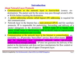


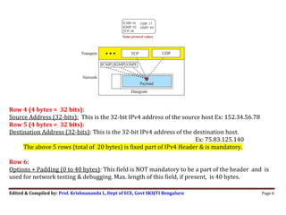

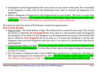

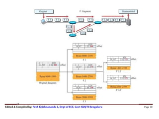


The document discusses network layer protocols and IPv4 specifically. It provides three key points: 1) IPv4 is the main network layer protocol in the Internet that provides "best effort" delivery of packets called datagrams from source to destination through various networks in a connectionless manner. 2) IPv4 packets, or datagrams, contain a header with fields that provide routing information and a payload section for data. The header fields include source and destination addresses, identification information, flags for fragmentation, and more. 3) IPv4 supports fragmentation of large datagrams into smaller pieces to accommodate the size constraints of different networks. The fragmentation process and header fields related to fragmentation are described.


![Attack surfaces and attack tress[inform]](https://cdn.slidesharecdn.com/ss_thumbnails/lecture03-260108015941-a4dee53b-thumbnail.jpg?width=640&height=640&fit=bounds)


