Download as PDF, PPTX

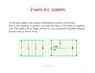
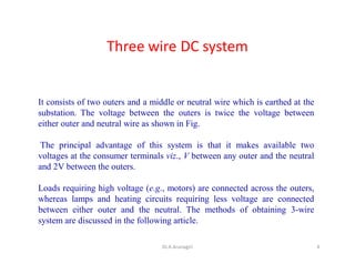
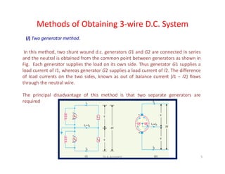
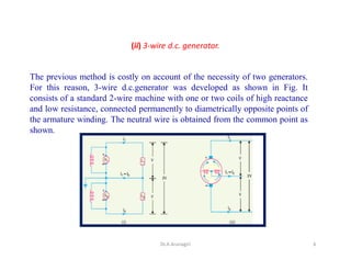
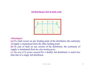


The document discusses D.C. distribution systems, including 2-wire and 3-wire configurations, methods for obtaining a 3-wire system, and a comparison of overhead vs. underground distribution systems. It also covers types of D.C. distributors and various feeding methods, detailing their characteristics, advantages, and disadvantages. Finally, the document highlights calculations related to voltage drop and power loss in both uniformly and concentrated loaded D.C. distributors.

![Power system planning & operation [eceg 4410]](https://cdn.slidesharecdn.com/ss_thumbnails/powersystemplanningoperationeceg-4410-130607134359-phpapp01-thumbnail.jpg?width=640&height=640&fit=bounds)