Download as PDF, PPTX


![Frequency-Shift Keying (FSK)
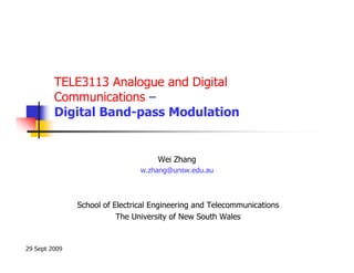
• In the time domain, the FSK signal is
represented by
⎡ t
⎤
s (t ) = Ac cos ⎢ωc t + D f ∫ m(t )dt ⎥
⎣ −∞ ⎦
m(t) is the baseband data signal.
Ac is the amplitude of the carrier.
Df is the frequency deviation [rad./volt/sec].](https://image.slidesharecdn.com/tele3113wk10tue-110604234819-phpapp02/85/Tele3113-wk10tue-11-320.jpg)


![Binary Phase-Shift Keying (BPSK)
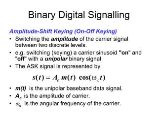
• Switching the phase of the carrier signal
between two discrete levels. Usually the two
levels differ by 180º.
• The BPSK signal is represented by
[
s ( t ) = Ac cos ω c t + D p m( t ) ]
m(t) is the baseband data signal.
Ac is the amplitude of the carrier.
Dp = is the peak phase deviation [rad./volt].](https://image.slidesharecdn.com/tele3113wk10tue-110604234819-phpapp02/85/Tele3113-wk10tue-14-320.jpg)


The document provides an overview of digital passband modulation techniques. It discusses binary modulation schemes including amplitude-shift keying (ASK), frequency-shift keying (FSK), and phase-shift keying (BPSK). It also covers differential phase-shift keying (DPSK), which removes phase ambiguity in BPSK using differential encoding and decoding. Key aspects like signal representation, spectrum, and detection methods are described for each technique.


