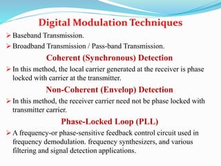
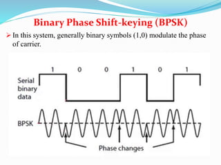
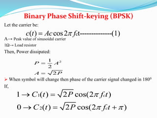
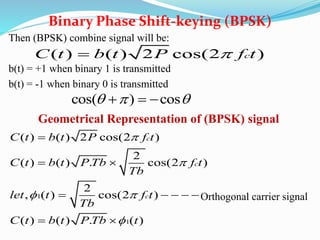
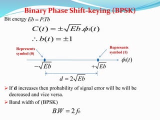
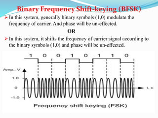
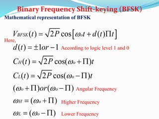
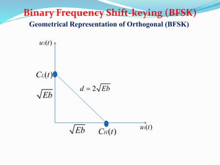
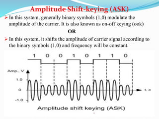
Instructor
Engr. Muhammad Yaseen
 Baseband Transmission.
 Broadband Transmission / Pass-band Transmission.
Coherent (Synchronous) Detection
 In this method, the local carrier generated at the receiver is phase
locked with carrier at the transmitter.
Non-Coherent (Envelop) Detection
 In this method, the receiver carrier need not be phase locked with
transmitter carrier.
Phase-Locked Loop (PLL)
 A frequency-or phase-sensitive feedback control circuit used in
frequency demodulation. frequency synthesizers, and various
filtering and signal detection applications.
Digital Modulation Techniques
 In this system, generally binary symbols (1,0) modulate the phase
of carrier.
Binary Phase Shift-keying (BPSK)
Let the carrier be:
A→ Peak value of sinusoidal carrier
1Ω→ Load resistor
Then, Power dissipated:
 When symbol will change then phase of the carrier signal changed in 1800
If,
Binary Phase Shift-keying (BPSK)
c( ) cos2 t--------------(1)c t Ac f
21
2
2
P A
A P


1
2
1 ( ) 2 cos(2 )
0 ( ) 2 cos(2 )
c
c
C t P f t
C t P f t

 
 
  
Then (BPSK) combine signal will be:
b(t) = +1 when binary 1 is transmitted
b(t) = -1 when binary 0 is transmitted
Geometrical Representation of (BPSK) signal
Orthogonal carrier signal
Binary Phase Shift-keying (BPSK)
( ) ( ) 2 cos(2 )cC t b t P f t
cos( ) cos    
1
1
( ) ( ) 2 cos(2 )
2
( ) ( ) . cos(2 )
2
, ( ) cos(2 )
( ) ( ) . ( )
c
c
c
C t b t P f t
C t b t P Tb f t
Tb
let t f t
Tb
C t b t P Tb t


 


 
    
 
Bit energy
 If d increases then probability of signal error will be will be
decreased and vice versa.
 Band width of (BPSK)
Binary Phase Shift-keying (BPSK)
.Eb PTb
1( ) . ( )
( ) 1
C t Eb t
b t
 
  
1( )t
Eb Eb
2d Eb
Represents
symbol (0)
Represents
symbol (1)
. 2 bBW f
 In this system, generally binary symbols (1,0) modulate the
frequency of carrier. And phase will be un-effected.
OR
 In this system, it shifts the frequency of carrier signal according to
the binary symbols (1,0) and phase will be un-effected.
Binary Frequency Shift-keying (BFSK)
Mathematical representation of BFSK
Here,
According to logic level 1 and 0
Binary Frequency Shift-keying (BFSK)
 ( ) 2 cos ( )
( ) 1 1
( ) 2 cos( )
( ) 2 cos( )
( ) ( )
( )
( )
BFSK o
H o
L o
o o
H o
L o
V t P t d t t
d t or
C t P t
C t P t
or



 
 
 
  
  
  
 
  
  
 
Angular Frequency
Higher Frequency
Lower Frequency
Geometrical Representation of Orthogonal (BFSK)
Binary Frequency Shift-keying (BFSK)
2d Eb
Eb
Eb ( )HC t
( )LC t
1( )u t
2( )u t
 In this system, generally binary symbols (1,0) modulate the
amplitude of the carrier. It is also known as on-off keying (ook)
OR
 In this system, it shifts the amplitude of carrier signal according to
the binary symbols (1,0) and frequency will be constant.
Amplitude Shift-keying (ASK)
 Modulation used to transmit analog data in the form of pulses
whose amplitude, width, or time portion is varied.
Pulse Modulation (PM)

Digital modulation techniques updated

  • 1.
  • 2.
     Baseband Transmission. Broadband Transmission / Pass-band Transmission. Coherent (Synchronous) Detection  In this method, the local carrier generated at the receiver is phase locked with carrier at the transmitter. Non-Coherent (Envelop) Detection  In this method, the receiver carrier need not be phase locked with transmitter carrier. Phase-Locked Loop (PLL)  A frequency-or phase-sensitive feedback control circuit used in frequency demodulation. frequency synthesizers, and various filtering and signal detection applications. Digital Modulation Techniques
  • 3.
     In thissystem, generally binary symbols (1,0) modulate the phase of carrier. Binary Phase Shift-keying (BPSK)
  • 4.
    Let the carrierbe: A→ Peak value of sinusoidal carrier 1Ω→ Load resistor Then, Power dissipated:  When symbol will change then phase of the carrier signal changed in 1800 If, Binary Phase Shift-keying (BPSK) c( ) cos2 t--------------(1)c t Ac f 21 2 2 P A A P   1 2 1 ( ) 2 cos(2 ) 0 ( ) 2 cos(2 ) c c C t P f t C t P f t        
  • 5.
    Then (BPSK) combinesignal will be: b(t) = +1 when binary 1 is transmitted b(t) = -1 when binary 0 is transmitted Geometrical Representation of (BPSK) signal Orthogonal carrier signal Binary Phase Shift-keying (BPSK) ( ) ( ) 2 cos(2 )cC t b t P f t cos( ) cos     1 1 ( ) ( ) 2 cos(2 ) 2 ( ) ( ) . cos(2 ) 2 , ( ) cos(2 ) ( ) ( ) . ( ) c c c C t b t P f t C t b t P Tb f t Tb let t f t Tb C t b t P Tb t               
  • 6.
    Bit energy  Ifd increases then probability of signal error will be will be decreased and vice versa.  Band width of (BPSK) Binary Phase Shift-keying (BPSK) .Eb PTb 1( ) . ( ) ( ) 1 C t Eb t b t      1( )t Eb Eb 2d Eb Represents symbol (0) Represents symbol (1) . 2 bBW f
  • 7.
     In thissystem, generally binary symbols (1,0) modulate the frequency of carrier. And phase will be un-effected. OR  In this system, it shifts the frequency of carrier signal according to the binary symbols (1,0) and phase will be un-effected. Binary Frequency Shift-keying (BFSK)
  • 8.
    Mathematical representation ofBFSK Here, According to logic level 1 and 0 Binary Frequency Shift-keying (BFSK)  ( ) 2 cos ( ) ( ) 1 1 ( ) 2 cos( ) ( ) 2 cos( ) ( ) ( ) ( ) ( ) BFSK o H o L o o o H o L o V t P t d t t d t or C t P t C t P t or                             Angular Frequency Higher Frequency Lower Frequency
  • 9.
    Geometrical Representation ofOrthogonal (BFSK) Binary Frequency Shift-keying (BFSK) 2d Eb Eb Eb ( )HC t ( )LC t 1( )u t 2( )u t
  • 10.
     In thissystem, generally binary symbols (1,0) modulate the amplitude of the carrier. It is also known as on-off keying (ook) OR  In this system, it shifts the amplitude of carrier signal according to the binary symbols (1,0) and frequency will be constant. Amplitude Shift-keying (ASK)
  • 11.
     Modulation usedto transmit analog data in the form of pulses whose amplitude, width, or time portion is varied. Pulse Modulation (PM)