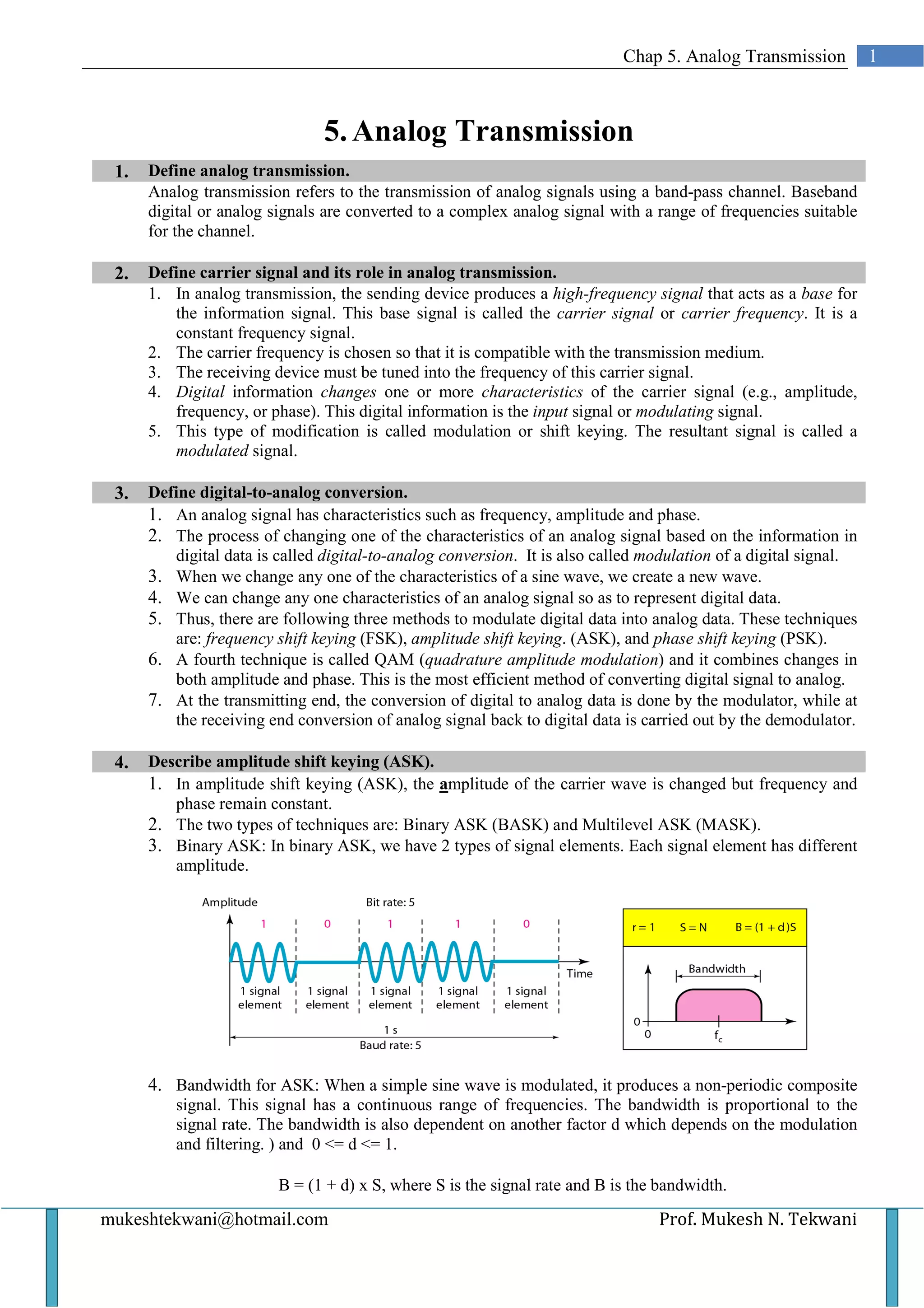
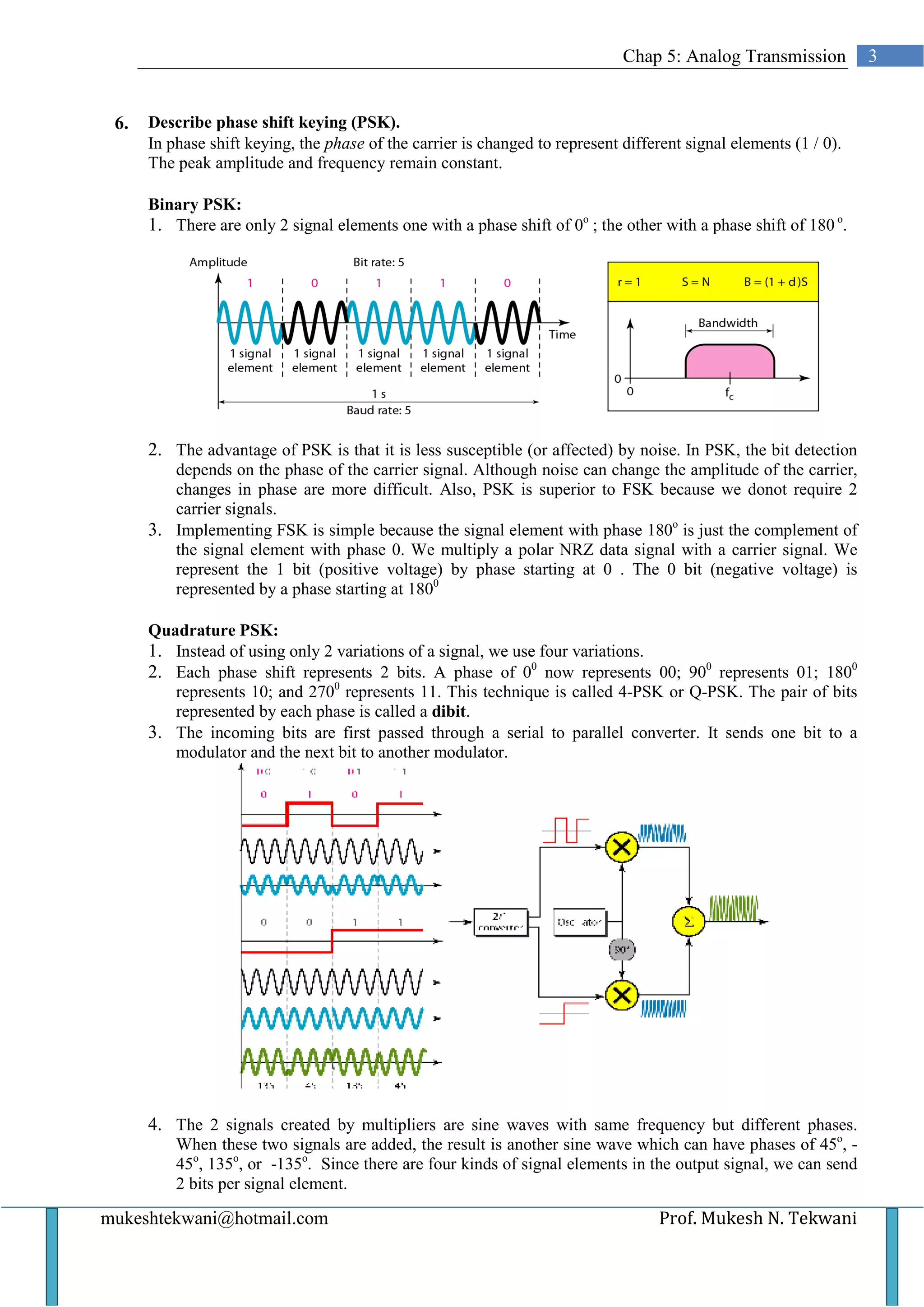
SlideShare a Scribd company logo
Chap 5. Analog Transmission           1


                                5. Analog Transmission
 1.   Define analog transmission.
      Analog transmission refers to the transmission of analog signals using a band-pass channel. Baseband
      digital or analog signals are converted to a complex analog signal with a range of frequencies suitable
      for the channel.

 2.   Define carrier signal and its role in analog transmission.
      1. In analog transmission, the sending device produces a high-frequency signal that acts as a base for
         the information signal. This base signal is called the carrier signal or carrier frequency. It is a
         constant frequency signal.
      2. The carrier frequency is chosen so that it is compatible with the transmission medium.
      3. The receiving device must be tuned into the frequency of this carrier signal.
      4. Digital information changes one or more characteristics of the carrier signal (e.g., amplitude,
         frequency, or phase). This digital information is the input signal or modulating signal.
      5. This type of modification is called modulation or shift keying. The resultant signal is called a
         modulated signal.

 3.   Define digital-to-analog conversion.
      1. An analog signal has characteristics such as frequency, amplitude and phase.
      2. The process of changing one of the characteristics of an analog signal based on the information in
         digital data is called digital-to-analog conversion. It is also called modulation of a digital signal.
      3. When we change any one of the characteristics of a sine wave, we create a new wave.
      4. We can change any one characteristics of an analog signal so as to represent digital data.
      5. Thus, there are following three methods to modulate digital data into analog data. These techniques
         are: frequency shift keying (FSK), amplitude shift keying. (ASK), and phase shift keying (PSK).
      6. A fourth technique is called QAM (quadrature amplitude modulation) and it combines changes in
         both amplitude and phase. This is the most efficient method of converting digital signal to analog.
      7. At the transmitting end, the conversion of digital to analog data is done by the modulator, while at
         the receiving end conversion of analog signal back to digital data is carried out by the demodulator.

 4.   Describe amplitude shift keying (ASK).
      1. In amplitude shift keying (ASK), the amplitude of the carrier wave is changed but frequency and
         phase remain constant.
      2. The two types of techniques are: Binary ASK (BASK) and Multilevel ASK (MASK).
      3. Binary ASK: In binary ASK, we have 2 types of signal elements. Each signal element has different
         amplitude.


      4. Bandwidth for ASK: When a simple sine wave is modulated, it produces a non-periodic composite
          signal. This signal has a continuous range of frequencies. The bandwidth is proportional to the
          signal rate. The bandwidth is also dependent on another factor d which depends on the modulation
          and filtering. ) and 0 <= d <= 1.

                         B = (1 + d) x S, where S is the signal rate and B is the bandwidth.

mukeshtekwani@hotmail.com                                                        Prof. Mukesh N. Tekwani
2    Analog Transmission


          Minimum bandwidth is obtained when d = 0 or B = S and maximum bandwidth is obtained when d = 1
          and B = 2S.

          5. From the diagram we observe that the middle of the bandwidth coincides with the carrier frequency
              fc. So if we have a bandpass channel available we can choose fc so that the modulated signal
              occupies the bandwidth.


          6. Consider a digital signal with a high voltage of 1V and a low voltage of 0 V. We multiply the
              digital signal by the carrier signal. When the amplitude of the digital signal is 1, the amplitude of
              the carrier frequency is max and when the amplitude of the digital signal becomes 0, the amplitude
              of the carrier signal is also 0.

          7. In full-duplex transmission, data has to be sent in
              both directions. The available bandwidth is
              divided into two with 2 carrier frequencies. The
              total bandwidth of 100 kHz is divided into 2 parts
              of 50 kHz each. The available bandwidth for
              each direction is now 50 kHz.

          Multilevel ASK:
          In multilevel ASK, there are more than 2 levels of the digital signal. We can use 4, 8, 16 or more
          different amplitudes for the signal and modulate the data using 2, 3, 4 or more bits at a time.

     5.   Describe frequency shift keying (FSK).
          1. In FSK, the frequency of the carrier is
             changed to represent the binary 1 and 0.
             For binary 0 the carrier frequency will be
             f1 and for binary 1, the frequency will be
             f 2.
          2. The frequency of the modulated signal is
             constant for the duration of one signal
             element (say binary 0) but changes for
             the next signal element (say binary 1).
          3. The peak amplitude and phase remain constant.
          4. Bandwidth for FSK: The middle of one bandwidth is f1 while
             the middle of the other bandwidth is f2. These two bandwidths
             are Δf apart from the midpoint between the two bands. The
             difference between the two frequencies is 2 Δf.

          Multilevel FSK: This is also called multiple FSK. More than 2
          frequencies are used. E.g., we can use 4 different frequencies to
          send 2 bits at a time. To send 3 bits at a time, we use 8 frequencies.


    Prof. Mukesh N Tekwani                                                         mukeshtekwani@hotmail.com
Chap 5: Analog Transmission          3


 6.   Describe phase shift keying (PSK).
      In phase shift keying, the phase of the carrier is changed to represent different signal elements (1 / 0).
      The peak amplitude and frequency remain constant.

      Binary PSK:
      1. There are only 2 signal elements one with a phase shift of 0o ; the other with a phase shift of 180 o.


      2. The advantage of PSK is that it is less susceptible (or affected) by noise. In PSK, the bit detection
         depends on the phase of the carrier signal. Although noise can change the amplitude of the carrier,
         changes in phase are more difficult. Also, PSK is superior to FSK because we donot require 2
         carrier signals.
      3. Implementing FSK is simple because the signal element with phase 180o is just the complement of
         the signal element with phase 0. We multiply a polar NRZ data signal with a carrier signal. We
         represent the 1 bit (positive voltage) by phase starting at 0 . The 0 bit (negative voltage) is
         represented by a phase starting at 1800

      Quadrature PSK:
      1. Instead of using only 2 variations of a signal, we use four variations.
      2. Each phase shift represents 2 bits. A phase of 00 now represents 00; 900 represents 01; 1800
         represents 10; and 2700 represents 11. This technique is called 4-PSK or Q-PSK. The pair of bits
         represented by each phase is called a dibit.
      3. The incoming bits are first passed through a serial to parallel converter. It sends one bit to a
         modulator and the next bit to another modulator.


      4. The 2 signals created by multipliers are sine waves with same frequency but different phases.
          When these two signals are added, the result is another sine wave which can have phases of 45o, -
          45o, 135o, or -135o. Since there are four kinds of signal elements in the output signal, we can send
          2 bits per signal element.

mukeshtekwani@hotmail.com                                                           Prof. Mukesh N. Tekwani
4    Analog Transmission


     7.   Describe Quadrature Amplitude Modulation (QAM).
          1. This modulation technique is a combination of ASK and PSK.
          2. In QAM technique, we change two characteristics – the amplitude of one carrier wave and the and
             the phase of the other carrier wave.
          3. The amplitude of the two carrier signals are different.

     8.   Define analog-to-analog conversion.
          1. Analog-to-analog conversion I the representation of analog information by an analog signal.
          2. Such a modulation is required if the medium is bandpass.
          3. Analog-to-analog conversion is achieved in 3 ways: Amplitude Modulation (AM), Frequency
             Modulation (FM), and Phase Modulation (PM)

     9.   Describe Amplitude Modulation (AM)
          1. Modulation is defined as the process of combining an input signal and a carrier frequency to
             produce a signal whose bandwidth is centered around fc.
          2. In AM, we use two signals: the carrier signal and the modulating signal. Both are analog signals.
          3. The carrier signal is modulated so that its amplitude varies with changes in the amplitude of the
             modulating signal.
          4. The frequency and phase of the carrier signal remain constant, only the amplitude changes.


          5. The modulating signal is the envelope of the carrier wave.
          6. The bandwidth of the AM signal is two times the bandwidth of the modulating signal. The central
             frequency is fc. The signal components above and below fc carry the same information.

          Why is modulation of analog signal necessary?
          Modulation of an analog signal is necessary for two reasons:
          a) A higher frequency may be needed for transmission of a signal. The size of the antenna decreases
             as the carrier frequency increases so a modulated signal is needed.
          b) Modulation permits frequency division multiplexing.

    10.   Describe Frequency Modulation (FM)
          1. In Frequency Modulation, the frequency of the carrier wave is changed to follow the changing
             amplitude of the modulating signal.
          2. The peak amplitude and phase of the carrier signal remain constant but as the amplitude of the
             modulating (or information) signal changes, the frequency o the carrier signal also changes.
          3. The total bandwidth of the FM signal is given by: BW = 2(1 + β)B, where β is the modulation
             index


    Prof. Mukesh N Tekwani                                                 mukeshtekwani@hotmail.com
Chap 5: Analog Transmission           5


11.   Discuss Phase Modulation (PM).
      1. In Phase Modulation, the phase of the carrier signal is changed in accordance with the changing
          amplitude of the modulating signal.
      2. The peak amplitude and frequency of the carrier signal remain constant, but the phase of the carrier
          changes with changes in amplitude of the information signal (or the modulating signal).


mukeshtekwani@hotmail.com                                                       Prof. Mukesh N. Tekwani

More Related Content

What's hot

Chapter 4 - Digital Transmission
Chapter 4 - Digital TransmissionChapter 4 - Digital Transmission
Chapter 4 - Digital Transmission
Wayne Jones Jnr
 
Chapter 6
Chapter 6Chapter 6
Chapter 6
Faisal Mehmood
 
2. data and signals
2. data and signals2. data and signals
2. data and signals
Humayoun Kabir
 
Error Detection and correction concepts in Data communication and networks
Error Detection and correction concepts in Data communication and networksError Detection and correction concepts in Data communication and networks
Error Detection and correction concepts in Data communication and networks
Nt Arvind
 
Digital Data to Digital Signal Conversion
Digital Data to Digital Signal ConversionDigital Data to Digital Signal Conversion
Digital Data to Digital Signal Conversion
Arafat Hossan
 
Data Communication & Computer Networks: Multi level, multi transition & block...
Data Communication & Computer Networks: Multi level, multi transition & block...Data Communication & Computer Networks: Multi level, multi transition & block...
Data Communication & Computer Networks: Multi level, multi transition & block...
Dr Rajiv Srivastava
 
5. protocol layering
5. protocol layering5. protocol layering
5. protocol layering
JAIGANESH SEKAR
 
Transmission impairments(presentation)
Transmission impairments(presentation)Transmission impairments(presentation)
Transmission impairments(presentation)
Vivek Kumar
 
Error Detection And Correction
Error Detection And CorrectionError Detection And Correction
Error Detection And Correction
Renu Kewalramani
 
Analog Transmissions
Analog TransmissionsAnalog Transmissions
Analog TransmissionsTechiNerd
 
Phase shift keying Presentation
Phase shift keying PresentationPhase shift keying Presentation
Phase shift keying Presentation
Pavan Goswami
 
Digital modulation basics(nnm)
Digital modulation basics(nnm)Digital modulation basics(nnm)
Digital modulation basics(nnm)
nnmaurya
 
HDLC
HDLCHDLC
Binary Pass-Band Modulation Techniques
Binary Pass-Band Modulation TechniquesBinary Pass-Band Modulation Techniques
Binary Pass-Band Modulation TechniquesSugeng Widodo
 
Block coding, error detection (Parity checking, Cyclic redundancy checking (C...
Block coding, error detection (Parity checking, Cyclic redundancy checking (C...Block coding, error detection (Parity checking, Cyclic redundancy checking (C...
Block coding, error detection (Parity checking, Cyclic redundancy checking (C...
Paulo_Vangui
 
Application Layer
Application Layer Application Layer
Application Layer
Dr Shashikant Athawale
 

What's hot (20)

Chapter 4 - Digital Transmission
Chapter 4 - Digital TransmissionChapter 4 - Digital Transmission
Chapter 4 - Digital Transmission
 
Chapter 6
Chapter 6Chapter 6
Chapter 6
 
2. data and signals
2. data and signals2. data and signals
2. data and signals
 
Error Detection and correction concepts in Data communication and networks
Error Detection and correction concepts in Data communication and networksError Detection and correction concepts in Data communication and networks
Error Detection and correction concepts in Data communication and networks
 
Unit 4
Unit 4Unit 4
Unit 4
 
Digital Data to Digital Signal Conversion
Digital Data to Digital Signal ConversionDigital Data to Digital Signal Conversion
Digital Data to Digital Signal Conversion
 
03 data transmission
03 data transmission03 data transmission
03 data transmission
 
Data Communication & Computer Networks: Multi level, multi transition & block...
Data Communication & Computer Networks: Multi level, multi transition & block...Data Communication & Computer Networks: Multi level, multi transition & block...
Data Communication & Computer Networks: Multi level, multi transition & block...
 
5. protocol layering
5. protocol layering5. protocol layering
5. protocol layering
 
Transmission impairments(presentation)
Transmission impairments(presentation)Transmission impairments(presentation)
Transmission impairments(presentation)
 
Error Detection And Correction
Error Detection And CorrectionError Detection And Correction
Error Detection And Correction
 
Analog Transmissions
Analog TransmissionsAnalog Transmissions
Analog Transmissions
 
Phase shift keying Presentation
Phase shift keying PresentationPhase shift keying Presentation
Phase shift keying Presentation
 
Ch 04
Ch 04Ch 04
Ch 04
 
Digital modulation basics(nnm)
Digital modulation basics(nnm)Digital modulation basics(nnm)
Digital modulation basics(nnm)
 
HDLC
HDLCHDLC
HDLC
 
Binary Pass-Band Modulation Techniques
Binary Pass-Band Modulation TechniquesBinary Pass-Band Modulation Techniques
Binary Pass-Band Modulation Techniques
 
Block coding, error detection (Parity checking, Cyclic redundancy checking (C...
Block coding, error detection (Parity checking, Cyclic redundancy checking (C...Block coding, error detection (Parity checking, Cyclic redundancy checking (C...
Block coding, error detection (Parity checking, Cyclic redundancy checking (C...
 
Lecture 17
Lecture 17Lecture 17
Lecture 17
 
Application Layer
Application Layer Application Layer
Application Layer
 

Viewers also liked

Data communication and network Chapter - 2
Data communication and network Chapter - 2Data communication and network Chapter - 2
Data communication and network Chapter - 2
Zafar Ayub
 
Chapter 26 - Remote Logging, Electronic Mail & File Transfer
Chapter 26 - Remote Logging, Electronic Mail & File TransferChapter 26 - Remote Logging, Electronic Mail & File Transfer
Chapter 26 - Remote Logging, Electronic Mail & File TransferWayne Jones Jnr
 
Data communications
Data communicationsData communications
Data communicationsUMaine
 
Digital data transmission,line coding and pulse shaping
Digital data transmission,line coding and pulse shapingDigital data transmission,line coding and pulse shaping
Digital data transmission,line coding and pulse shaping
Aayush Kumar
 
Chap5 analog transmission
Chap5 analog transmissionChap5 analog transmission
Chap5 analog transmissionarslan_akbar90
 
Data transmission
Data transmissionData transmission
Secure Data Transmission
Secure Data TransmissionSecure Data Transmission
Secure Data Transmission
bjp4642
 
Analog Transmission
Analog TransmissionAnalog Transmission
Analog Transmission
Shiraz316
 
Analog Transmission
Analog TransmissionAnalog Transmission
Analog Transmission
Md Abdus Sobur Sikdar
 
Digital & analog transmission
Digital & analog transmissionDigital & analog transmission
Digital & analog transmission
Jeffery Vava
 
2[1].1 data transmission
2[1].1 data transmission2[1].1 data transmission
2[1].1 data transmissionHattori Sidek
 

Viewers also liked (20)

Data communication and network Chapter - 2
Data communication and network Chapter - 2Data communication and network Chapter - 2
Data communication and network Chapter - 2
 
Ch10
Ch10Ch10
Ch10
 
Chapter 26 - Remote Logging, Electronic Mail & File Transfer
Chapter 26 - Remote Logging, Electronic Mail & File TransferChapter 26 - Remote Logging, Electronic Mail & File Transfer
Chapter 26 - Remote Logging, Electronic Mail & File Transfer
 
Data communications
Data communicationsData communications
Data communications
 
Digital data transmission,line coding and pulse shaping
Digital data transmission,line coding and pulse shapingDigital data transmission,line coding and pulse shaping
Digital data transmission,line coding and pulse shaping
 
Ch06
Ch06Ch06
Ch06
 
Ch18
Ch18Ch18
Ch18
 
Chap5 analog transmission
Chap5 analog transmissionChap5 analog transmission
Chap5 analog transmission
 
Data transmission
Data transmissionData transmission
Data transmission
 
Serial transmission
Serial transmissionSerial transmission
Serial transmission
 
Secure Data Transmission
Secure Data TransmissionSecure Data Transmission
Secure Data Transmission
 
Ch25
Ch25Ch25
Ch25
 
Analog Transmission
Analog TransmissionAnalog Transmission
Analog Transmission
 
Analog Transmission
Analog TransmissionAnalog Transmission
Analog Transmission
 
Digital & analog transmission
Digital & analog transmissionDigital & analog transmission
Digital & analog transmission
 
2[1].1 data transmission
2[1].1 data transmission2[1].1 data transmission
2[1].1 data transmission
 
Ch15
Ch15Ch15
Ch15
 
Ch31
Ch31Ch31
Ch31
 
Ch08
Ch08Ch08
Ch08
 
Ch21
Ch21Ch21
Ch21
 

Similar to Chap 5 analog transmission

dspppt.pptx
dspppt.pptxdspppt.pptx
dspppt.pptx
AbhishekKumar129104
 
DCN 5th ed. slides ch05 Analog Transmission.pdf
DCN 5th ed. slides ch05 Analog Transmission.pdfDCN 5th ed. slides ch05 Analog Transmission.pdf
DCN 5th ed. slides ch05 Analog Transmission.pdf
Bilal Munir Mughal
 
05 analog transmission
05 analog transmission05 analog transmission
05 analog transmission
Meenakshi Paul
 
Digital To Analog Conversion
Digital To Analog ConversionDigital To Analog Conversion
Digital To Analog Conversion
Sialkot
 
Rf fundamentals
Rf fundamentalsRf fundamentals
Rf fundamentals
Shahanawaz Mansuri
 
Lecture8 digitaltoanalogconversion
Lecture8 digitaltoanalogconversionLecture8 digitaltoanalogconversion
Lecture8 digitaltoanalogconversionH K
 
Linear modulation
Linear modulation Linear modulation
Linear modulation
Punk Pankaj
 
Ch4 linear modulation pg 111
Ch4 linear modulation pg 111Ch4 linear modulation pg 111
Ch4 linear modulation pg 111
Prateek Omer
 
ADC Unit 1.pdf
ADC Unit 1.pdfADC Unit 1.pdf
ADC Unit 1.pdf
BunnyYadav7
 
Modulation of digital_and_analog_data
Modulation of digital_and_analog_dataModulation of digital_and_analog_data
Modulation of digital_and_analog_data
Muhamamd Awaissaleem
 
Digital modulation technique
Digital modulation techniqueDigital modulation technique
Digital modulation technique
Nidhi Baranwal
 
Networking notes part2 final
Networking notes part2 finalNetworking notes part2 final
Networking notes part2 final
SHARVAN PRAJAPATI
 
mod.pptx
mod.pptxmod.pptx
mod.pptx
AbdullahOmar64
 
Communication system lec 8
Communication system lec 8Communication system lec 8
Communication system lec 8
ZareenRauf1
 
UNIT-4 Baseband Digital Modulation.pdf
UNIT-4 Baseband Digital Modulation.pdfUNIT-4 Baseband Digital Modulation.pdf
UNIT-4 Baseband Digital Modulation.pdf
Matrusri Engineering College
 
Data Encoding
Data EncodingData Encoding
Data EncodingLuka M G
 

Similar to Chap 5 analog transmission (20)

ASK,FSK and M-PSK using Matlab
ASK,FSK and M-PSK using MatlabASK,FSK and M-PSK using Matlab
ASK,FSK and M-PSK using Matlab
 
Lecture 11
Lecture 11Lecture 11
Lecture 11
 
dspppt.pptx
dspppt.pptxdspppt.pptx
dspppt.pptx
 
DCN 5th ed. slides ch05 Analog Transmission.pdf
DCN 5th ed. slides ch05 Analog Transmission.pdfDCN 5th ed. slides ch05 Analog Transmission.pdf
DCN 5th ed. slides ch05 Analog Transmission.pdf
 
05 analog transmission
05 analog transmission05 analog transmission
05 analog transmission
 
Digital To Analog Conversion
Digital To Analog ConversionDigital To Analog Conversion
Digital To Analog Conversion
 
Rf fundamentals
Rf fundamentalsRf fundamentals
Rf fundamentals
 
Lecture8 digitaltoanalogconversion
Lecture8 digitaltoanalogconversionLecture8 digitaltoanalogconversion
Lecture8 digitaltoanalogconversion
 
Linear modulation
Linear modulation Linear modulation
Linear modulation
 
Mod1
Mod1Mod1
Mod1
 
Mod1
Mod1Mod1
Mod1
 
Ch4 linear modulation pg 111
Ch4 linear modulation pg 111Ch4 linear modulation pg 111
Ch4 linear modulation pg 111
 
ADC Unit 1.pdf
ADC Unit 1.pdfADC Unit 1.pdf
ADC Unit 1.pdf
 
Modulation of digital_and_analog_data
Modulation of digital_and_analog_dataModulation of digital_and_analog_data
Modulation of digital_and_analog_data
 
Digital modulation technique
Digital modulation techniqueDigital modulation technique
Digital modulation technique
 
Networking notes part2 final
Networking notes part2 finalNetworking notes part2 final
Networking notes part2 final
 
mod.pptx
mod.pptxmod.pptx
mod.pptx
 
Communication system lec 8
Communication system lec 8Communication system lec 8
Communication system lec 8
 
UNIT-4 Baseband Digital Modulation.pdf
UNIT-4 Baseband Digital Modulation.pdfUNIT-4 Baseband Digital Modulation.pdf
UNIT-4 Baseband Digital Modulation.pdf
 
Data Encoding
Data EncodingData Encoding
Data Encoding
 

More from Mukesh Tekwani

Computer Science Made Easy - Youtube Channel
Computer Science Made Easy - Youtube ChannelComputer Science Made Easy - Youtube Channel
Computer Science Made Easy - Youtube Channel
Mukesh Tekwani
 
The Elphinstonian 1988-College Building Centenary Number (2).pdf
The Elphinstonian 1988-College Building Centenary Number (2).pdfThe Elphinstonian 1988-College Building Centenary Number (2).pdf
The Elphinstonian 1988-College Building Centenary Number (2).pdf
Mukesh Tekwani
 
Circular motion
Circular motionCircular motion
Circular motion
Mukesh Tekwani
 
Gravitation
GravitationGravitation
Gravitation
Mukesh Tekwani
 
ISCE-Class 12-Question Bank - Electrostatics - Physics
ISCE-Class 12-Question Bank - Electrostatics  -  PhysicsISCE-Class 12-Question Bank - Electrostatics  -  Physics
ISCE-Class 12-Question Bank - Electrostatics - Physics
Mukesh Tekwani
 
Hexadecimal to binary conversion
Hexadecimal to binary conversion Hexadecimal to binary conversion
Hexadecimal to binary conversion
Mukesh Tekwani
 
Hexadecimal to decimal conversion
Hexadecimal to decimal conversion Hexadecimal to decimal conversion
Hexadecimal to decimal conversion
Mukesh Tekwani
 
Hexadecimal to octal conversion
Hexadecimal to octal conversionHexadecimal to octal conversion
Hexadecimal to octal conversion
Mukesh Tekwani
 
Gray code to binary conversion
Gray code to binary conversion Gray code to binary conversion
Gray code to binary conversion
Mukesh Tekwani
 
What is Gray Code?
What is Gray Code? What is Gray Code?
What is Gray Code?
Mukesh Tekwani
 
Decimal to Binary conversion
Decimal to Binary conversionDecimal to Binary conversion
Decimal to Binary conversion
Mukesh Tekwani
 
Video Lectures for IGCSE Physics 2020-21
Video Lectures for IGCSE Physics 2020-21Video Lectures for IGCSE Physics 2020-21
Video Lectures for IGCSE Physics 2020-21
Mukesh Tekwani
 
Refraction and dispersion of light through a prism
Refraction and dispersion of light through a prismRefraction and dispersion of light through a prism
Refraction and dispersion of light through a prism
Mukesh Tekwani
 
Refraction of light at a plane surface
Refraction of light at a plane surfaceRefraction of light at a plane surface
Refraction of light at a plane surface
Mukesh Tekwani
 
Spherical mirrors
Spherical mirrorsSpherical mirrors
Spherical mirrors
Mukesh Tekwani
 
Atom, origin of spectra Bohr's theory of hydrogen atom
Atom, origin of spectra Bohr's theory of hydrogen atomAtom, origin of spectra Bohr's theory of hydrogen atom
Atom, origin of spectra Bohr's theory of hydrogen atom
Mukesh Tekwani
 
Refraction of light at spherical surfaces of lenses
Refraction of light at spherical surfaces of lensesRefraction of light at spherical surfaces of lenses
Refraction of light at spherical surfaces of lenses
Mukesh Tekwani
 
ISCE (XII) - PHYSICS BOARD EXAM FEB 2020 - WEIGHTAGE
ISCE (XII) - PHYSICS BOARD EXAM FEB 2020 - WEIGHTAGEISCE (XII) - PHYSICS BOARD EXAM FEB 2020 - WEIGHTAGE
ISCE (XII) - PHYSICS BOARD EXAM FEB 2020 - WEIGHTAGE
Mukesh Tekwani
 
Cyber Laws
Cyber LawsCyber Laws
Cyber Laws
Mukesh Tekwani
 
XML
XMLXML

More from Mukesh Tekwani (20)

Computer Science Made Easy - Youtube Channel
Computer Science Made Easy - Youtube ChannelComputer Science Made Easy - Youtube Channel
Computer Science Made Easy - Youtube Channel
 
The Elphinstonian 1988-College Building Centenary Number (2).pdf
The Elphinstonian 1988-College Building Centenary Number (2).pdfThe Elphinstonian 1988-College Building Centenary Number (2).pdf
The Elphinstonian 1988-College Building Centenary Number (2).pdf
 
Circular motion
Circular motionCircular motion
Circular motion
 
Gravitation
GravitationGravitation
Gravitation
 
ISCE-Class 12-Question Bank - Electrostatics - Physics
ISCE-Class 12-Question Bank - Electrostatics  -  PhysicsISCE-Class 12-Question Bank - Electrostatics  -  Physics
ISCE-Class 12-Question Bank - Electrostatics - Physics
 
Hexadecimal to binary conversion
Hexadecimal to binary conversion Hexadecimal to binary conversion
Hexadecimal to binary conversion
 
Hexadecimal to decimal conversion
Hexadecimal to decimal conversion Hexadecimal to decimal conversion
Hexadecimal to decimal conversion
 
Hexadecimal to octal conversion
Hexadecimal to octal conversionHexadecimal to octal conversion
Hexadecimal to octal conversion
 
Gray code to binary conversion
Gray code to binary conversion Gray code to binary conversion
Gray code to binary conversion
 
What is Gray Code?
What is Gray Code? What is Gray Code?
What is Gray Code?
 
Decimal to Binary conversion
Decimal to Binary conversionDecimal to Binary conversion
Decimal to Binary conversion
 
Video Lectures for IGCSE Physics 2020-21
Video Lectures for IGCSE Physics 2020-21Video Lectures for IGCSE Physics 2020-21
Video Lectures for IGCSE Physics 2020-21
 
Refraction and dispersion of light through a prism
Refraction and dispersion of light through a prismRefraction and dispersion of light through a prism
Refraction and dispersion of light through a prism
 
Refraction of light at a plane surface
Refraction of light at a plane surfaceRefraction of light at a plane surface
Refraction of light at a plane surface
 
Spherical mirrors
Spherical mirrorsSpherical mirrors
Spherical mirrors
 
Atom, origin of spectra Bohr's theory of hydrogen atom
Atom, origin of spectra Bohr's theory of hydrogen atomAtom, origin of spectra Bohr's theory of hydrogen atom
Atom, origin of spectra Bohr's theory of hydrogen atom
 
Refraction of light at spherical surfaces of lenses
Refraction of light at spherical surfaces of lensesRefraction of light at spherical surfaces of lenses
Refraction of light at spherical surfaces of lenses
 
ISCE (XII) - PHYSICS BOARD EXAM FEB 2020 - WEIGHTAGE
ISCE (XII) - PHYSICS BOARD EXAM FEB 2020 - WEIGHTAGEISCE (XII) - PHYSICS BOARD EXAM FEB 2020 - WEIGHTAGE
ISCE (XII) - PHYSICS BOARD EXAM FEB 2020 - WEIGHTAGE
 
Cyber Laws
Cyber LawsCyber Laws
Cyber Laws
 
XML
XMLXML
XML
 

Recently uploaded

Introduction to CHERI technology - Cybersecurity
Introduction to CHERI technology - CybersecurityIntroduction to CHERI technology - Cybersecurity
Introduction to CHERI technology - Cybersecurity
mikeeftimakis1
 
UiPath Test Automation using UiPath Test Suite series, part 4
UiPath Test Automation using UiPath Test Suite series, part 4UiPath Test Automation using UiPath Test Suite series, part 4
UiPath Test Automation using UiPath Test Suite series, part 4
DianaGray10
 
Securing your Kubernetes cluster_ a step-by-step guide to success !
Securing your Kubernetes cluster_ a step-by-step guide to success !Securing your Kubernetes cluster_ a step-by-step guide to success !
Securing your Kubernetes cluster_ a step-by-step guide to success !
KatiaHIMEUR1
 
Communications Mining Series - Zero to Hero - Session 1
Communications Mining Series - Zero to Hero - Session 1Communications Mining Series - Zero to Hero - Session 1
Communications Mining Series - Zero to Hero - Session 1
DianaGray10
 
UiPath Test Automation using UiPath Test Suite series, part 5
UiPath Test Automation using UiPath Test Suite series, part 5UiPath Test Automation using UiPath Test Suite series, part 5
UiPath Test Automation using UiPath Test Suite series, part 5
DianaGray10
 
Generative AI Deep Dive: Advancing from Proof of Concept to Production
Generative AI Deep Dive: Advancing from Proof of Concept to ProductionGenerative AI Deep Dive: Advancing from Proof of Concept to Production
Generative AI Deep Dive: Advancing from Proof of Concept to Production
Aggregage
 
Free Complete Python - A step towards Data Science
Free Complete Python - A step towards Data ScienceFree Complete Python - A step towards Data Science
Free Complete Python - A step towards Data Science
RinaMondal9
 
FIDO Alliance Osaka Seminar: FIDO Security Aspects.pdf
FIDO Alliance Osaka Seminar: FIDO Security Aspects.pdfFIDO Alliance Osaka Seminar: FIDO Security Aspects.pdf
FIDO Alliance Osaka Seminar: FIDO Security Aspects.pdf
FIDO Alliance
 
GraphSummit Singapore | The Future of Agility: Supercharging Digital Transfor...
GraphSummit Singapore | The Future of Agility: Supercharging Digital Transfor...GraphSummit Singapore | The Future of Agility: Supercharging Digital Transfor...
GraphSummit Singapore | The Future of Agility: Supercharging Digital Transfor...
Neo4j
 
Uni Systems Copilot event_05062024_C.Vlachos.pdf
Uni Systems Copilot event_05062024_C.Vlachos.pdfUni Systems Copilot event_05062024_C.Vlachos.pdf
Uni Systems Copilot event_05062024_C.Vlachos.pdf
Uni Systems S.M.S.A.
 
GDG Cloud Southlake #33: Boule & Rebala: Effective AppSec in SDLC using Deplo...
GDG Cloud Southlake #33: Boule & Rebala: Effective AppSec in SDLC using Deplo...GDG Cloud Southlake #33: Boule & Rebala: Effective AppSec in SDLC using Deplo...
GDG Cloud Southlake #33: Boule & Rebala: Effective AppSec in SDLC using Deplo...
James Anderson
 
20240605 QFM017 Machine Intelligence Reading List May 2024
20240605 QFM017 Machine Intelligence Reading List May 202420240605 QFM017 Machine Intelligence Reading List May 2024
20240605 QFM017 Machine Intelligence Reading List May 2024
Matthew Sinclair
 
Essentials of Automations: The Art of Triggers and Actions in FME
Essentials of Automations: The Art of Triggers and Actions in FMEEssentials of Automations: The Art of Triggers and Actions in FME
Essentials of Automations: The Art of Triggers and Actions in FME
Safe Software
 
FIDO Alliance Osaka Seminar: Passkeys and the Road Ahead.pdf
FIDO Alliance Osaka Seminar: Passkeys and the Road Ahead.pdfFIDO Alliance Osaka Seminar: Passkeys and the Road Ahead.pdf
FIDO Alliance Osaka Seminar: Passkeys and the Road Ahead.pdf
FIDO Alliance
 
GridMate - End to end testing is a critical piece to ensure quality and avoid...
GridMate - End to end testing is a critical piece to ensure quality and avoid...GridMate - End to end testing is a critical piece to ensure quality and avoid...
GridMate - End to end testing is a critical piece to ensure quality and avoid...
ThomasParaiso2
 
Secstrike : Reverse Engineering & Pwnable tools for CTF.pptx
Secstrike : Reverse Engineering & Pwnable tools for CTF.pptxSecstrike : Reverse Engineering & Pwnable tools for CTF.pptx
Secstrike : Reverse Engineering & Pwnable tools for CTF.pptx
nkrafacyberclub
 
The Future of Platform Engineering
The Future of Platform EngineeringThe Future of Platform Engineering
The Future of Platform Engineering
Jemma Hussein Allen
 
PHP Frameworks: I want to break free (IPC Berlin 2024)
PHP Frameworks: I want to break free (IPC Berlin 2024)PHP Frameworks: I want to break free (IPC Berlin 2024)
PHP Frameworks: I want to break free (IPC Berlin 2024)
Ralf Eggert
 
GraphSummit Singapore | Enhancing Changi Airport Group's Passenger Experience...
GraphSummit Singapore | Enhancing Changi Airport Group's Passenger Experience...GraphSummit Singapore | Enhancing Changi Airport Group's Passenger Experience...
GraphSummit Singapore | Enhancing Changi Airport Group's Passenger Experience...
Neo4j
 
Pushing the limits of ePRTC: 100ns holdover for 100 days
Pushing the limits of ePRTC: 100ns holdover for 100 daysPushing the limits of ePRTC: 100ns holdover for 100 days
Pushing the limits of ePRTC: 100ns holdover for 100 days
Adtran
 

Recently uploaded (20)

Introduction to CHERI technology - Cybersecurity
Introduction to CHERI technology - CybersecurityIntroduction to CHERI technology - Cybersecurity
Introduction to CHERI technology - Cybersecurity
 
UiPath Test Automation using UiPath Test Suite series, part 4
UiPath Test Automation using UiPath Test Suite series, part 4UiPath Test Automation using UiPath Test Suite series, part 4
UiPath Test Automation using UiPath Test Suite series, part 4
 
Securing your Kubernetes cluster_ a step-by-step guide to success !
Securing your Kubernetes cluster_ a step-by-step guide to success !Securing your Kubernetes cluster_ a step-by-step guide to success !
Securing your Kubernetes cluster_ a step-by-step guide to success !
 
Communications Mining Series - Zero to Hero - Session 1
Communications Mining Series - Zero to Hero - Session 1Communications Mining Series - Zero to Hero - Session 1
Communications Mining Series - Zero to Hero - Session 1
 
UiPath Test Automation using UiPath Test Suite series, part 5
UiPath Test Automation using UiPath Test Suite series, part 5UiPath Test Automation using UiPath Test Suite series, part 5
UiPath Test Automation using UiPath Test Suite series, part 5
 
Generative AI Deep Dive: Advancing from Proof of Concept to Production
Generative AI Deep Dive: Advancing from Proof of Concept to ProductionGenerative AI Deep Dive: Advancing from Proof of Concept to Production
Generative AI Deep Dive: Advancing from Proof of Concept to Production
 
Free Complete Python - A step towards Data Science
Free Complete Python - A step towards Data ScienceFree Complete Python - A step towards Data Science
Free Complete Python - A step towards Data Science
 
FIDO Alliance Osaka Seminar: FIDO Security Aspects.pdf
FIDO Alliance Osaka Seminar: FIDO Security Aspects.pdfFIDO Alliance Osaka Seminar: FIDO Security Aspects.pdf
FIDO Alliance Osaka Seminar: FIDO Security Aspects.pdf
 
GraphSummit Singapore | The Future of Agility: Supercharging Digital Transfor...
GraphSummit Singapore | The Future of Agility: Supercharging Digital Transfor...GraphSummit Singapore | The Future of Agility: Supercharging Digital Transfor...
GraphSummit Singapore | The Future of Agility: Supercharging Digital Transfor...
 
Uni Systems Copilot event_05062024_C.Vlachos.pdf
Uni Systems Copilot event_05062024_C.Vlachos.pdfUni Systems Copilot event_05062024_C.Vlachos.pdf
Uni Systems Copilot event_05062024_C.Vlachos.pdf
 
GDG Cloud Southlake #33: Boule & Rebala: Effective AppSec in SDLC using Deplo...
GDG Cloud Southlake #33: Boule & Rebala: Effective AppSec in SDLC using Deplo...GDG Cloud Southlake #33: Boule & Rebala: Effective AppSec in SDLC using Deplo...
GDG Cloud Southlake #33: Boule & Rebala: Effective AppSec in SDLC using Deplo...
 
20240605 QFM017 Machine Intelligence Reading List May 2024
20240605 QFM017 Machine Intelligence Reading List May 202420240605 QFM017 Machine Intelligence Reading List May 2024
20240605 QFM017 Machine Intelligence Reading List May 2024
 
Essentials of Automations: The Art of Triggers and Actions in FME
Essentials of Automations: The Art of Triggers and Actions in FMEEssentials of Automations: The Art of Triggers and Actions in FME
Essentials of Automations: The Art of Triggers and Actions in FME
 
FIDO Alliance Osaka Seminar: Passkeys and the Road Ahead.pdf
FIDO Alliance Osaka Seminar: Passkeys and the Road Ahead.pdfFIDO Alliance Osaka Seminar: Passkeys and the Road Ahead.pdf
FIDO Alliance Osaka Seminar: Passkeys and the Road Ahead.pdf
 
GridMate - End to end testing is a critical piece to ensure quality and avoid...
GridMate - End to end testing is a critical piece to ensure quality and avoid...GridMate - End to end testing is a critical piece to ensure quality and avoid...
GridMate - End to end testing is a critical piece to ensure quality and avoid...
 
Secstrike : Reverse Engineering & Pwnable tools for CTF.pptx
Secstrike : Reverse Engineering & Pwnable tools for CTF.pptxSecstrike : Reverse Engineering & Pwnable tools for CTF.pptx
Secstrike : Reverse Engineering & Pwnable tools for CTF.pptx
 
The Future of Platform Engineering
The Future of Platform EngineeringThe Future of Platform Engineering
The Future of Platform Engineering
 
PHP Frameworks: I want to break free (IPC Berlin 2024)
PHP Frameworks: I want to break free (IPC Berlin 2024)PHP Frameworks: I want to break free (IPC Berlin 2024)
PHP Frameworks: I want to break free (IPC Berlin 2024)
 
GraphSummit Singapore | Enhancing Changi Airport Group's Passenger Experience...
GraphSummit Singapore | Enhancing Changi Airport Group's Passenger Experience...GraphSummit Singapore | Enhancing Changi Airport Group's Passenger Experience...
GraphSummit Singapore | Enhancing Changi Airport Group's Passenger Experience...
 
Pushing the limits of ePRTC: 100ns holdover for 100 days
Pushing the limits of ePRTC: 100ns holdover for 100 daysPushing the limits of ePRTC: 100ns holdover for 100 days
Pushing the limits of ePRTC: 100ns holdover for 100 days
 

Chap 5 analog transmission

  • 1. Chap 5. Analog Transmission 1 5. Analog Transmission 1. Define analog transmission. Analog transmission refers to the transmission of analog signals using a band-pass channel. Baseband digital or analog signals are converted to a complex analog signal with a range of frequencies suitable for the channel. 2. Define carrier signal and its role in analog transmission. 1. In analog transmission, the sending device produces a high-frequency signal that acts as a base for the information signal. This base signal is called the carrier signal or carrier frequency. It is a constant frequency signal. 2. The carrier frequency is chosen so that it is compatible with the transmission medium. 3. The receiving device must be tuned into the frequency of this carrier signal. 4. Digital information changes one or more characteristics of the carrier signal (e.g., amplitude, frequency, or phase). This digital information is the input signal or modulating signal. 5. This type of modification is called modulation or shift keying. The resultant signal is called a modulated signal. 3. Define digital-to-analog conversion. 1. An analog signal has characteristics such as frequency, amplitude and phase. 2. The process of changing one of the characteristics of an analog signal based on the information in digital data is called digital-to-analog conversion. It is also called modulation of a digital signal. 3. When we change any one of the characteristics of a sine wave, we create a new wave. 4. We can change any one characteristics of an analog signal so as to represent digital data. 5. Thus, there are following three methods to modulate digital data into analog data. These techniques are: frequency shift keying (FSK), amplitude shift keying. (ASK), and phase shift keying (PSK). 6. A fourth technique is called QAM (quadrature amplitude modulation) and it combines changes in both amplitude and phase. This is the most efficient method of converting digital signal to analog. 7. At the transmitting end, the conversion of digital to analog data is done by the modulator, while at the receiving end conversion of analog signal back to digital data is carried out by the demodulator. 4. Describe amplitude shift keying (ASK). 1. In amplitude shift keying (ASK), the amplitude of the carrier wave is changed but frequency and phase remain constant. 2. The two types of techniques are: Binary ASK (BASK) and Multilevel ASK (MASK). 3. Binary ASK: In binary ASK, we have 2 types of signal elements. Each signal element has different amplitude. 4. Bandwidth for ASK: When a simple sine wave is modulated, it produces a non-periodic composite signal. This signal has a continuous range of frequencies. The bandwidth is proportional to the signal rate. The bandwidth is also dependent on another factor d which depends on the modulation and filtering. ) and 0 <= d <= 1. B = (1 + d) x S, where S is the signal rate and B is the bandwidth. mukeshtekwani@hotmail.com Prof. Mukesh N. Tekwani
  • 2. 2 Analog Transmission Minimum bandwidth is obtained when d = 0 or B = S and maximum bandwidth is obtained when d = 1 and B = 2S. 5. From the diagram we observe that the middle of the bandwidth coincides with the carrier frequency fc. So if we have a bandpass channel available we can choose fc so that the modulated signal occupies the bandwidth. 6. Consider a digital signal with a high voltage of 1V and a low voltage of 0 V. We multiply the digital signal by the carrier signal. When the amplitude of the digital signal is 1, the amplitude of the carrier frequency is max and when the amplitude of the digital signal becomes 0, the amplitude of the carrier signal is also 0. 7. In full-duplex transmission, data has to be sent in both directions. The available bandwidth is divided into two with 2 carrier frequencies. The total bandwidth of 100 kHz is divided into 2 parts of 50 kHz each. The available bandwidth for each direction is now 50 kHz. Multilevel ASK: In multilevel ASK, there are more than 2 levels of the digital signal. We can use 4, 8, 16 or more different amplitudes for the signal and modulate the data using 2, 3, 4 or more bits at a time. 5. Describe frequency shift keying (FSK). 1. In FSK, the frequency of the carrier is changed to represent the binary 1 and 0. For binary 0 the carrier frequency will be f1 and for binary 1, the frequency will be f 2. 2. The frequency of the modulated signal is constant for the duration of one signal element (say binary 0) but changes for the next signal element (say binary 1). 3. The peak amplitude and phase remain constant. 4. Bandwidth for FSK: The middle of one bandwidth is f1 while the middle of the other bandwidth is f2. These two bandwidths are Δf apart from the midpoint between the two bands. The difference between the two frequencies is 2 Δf. Multilevel FSK: This is also called multiple FSK. More than 2 frequencies are used. E.g., we can use 4 different frequencies to send 2 bits at a time. To send 3 bits at a time, we use 8 frequencies. Prof. Mukesh N Tekwani mukeshtekwani@hotmail.com
  • 3. Chap 5: Analog Transmission 3 6. Describe phase shift keying (PSK). In phase shift keying, the phase of the carrier is changed to represent different signal elements (1 / 0). The peak amplitude and frequency remain constant. Binary PSK: 1. There are only 2 signal elements one with a phase shift of 0o ; the other with a phase shift of 180 o. 2. The advantage of PSK is that it is less susceptible (or affected) by noise. In PSK, the bit detection depends on the phase of the carrier signal. Although noise can change the amplitude of the carrier, changes in phase are more difficult. Also, PSK is superior to FSK because we donot require 2 carrier signals. 3. Implementing FSK is simple because the signal element with phase 180o is just the complement of the signal element with phase 0. We multiply a polar NRZ data signal with a carrier signal. We represent the 1 bit (positive voltage) by phase starting at 0 . The 0 bit (negative voltage) is represented by a phase starting at 1800 Quadrature PSK: 1. Instead of using only 2 variations of a signal, we use four variations. 2. Each phase shift represents 2 bits. A phase of 00 now represents 00; 900 represents 01; 1800 represents 10; and 2700 represents 11. This technique is called 4-PSK or Q-PSK. The pair of bits represented by each phase is called a dibit. 3. The incoming bits are first passed through a serial to parallel converter. It sends one bit to a modulator and the next bit to another modulator. 4. The 2 signals created by multipliers are sine waves with same frequency but different phases. When these two signals are added, the result is another sine wave which can have phases of 45o, - 45o, 135o, or -135o. Since there are four kinds of signal elements in the output signal, we can send 2 bits per signal element. mukeshtekwani@hotmail.com Prof. Mukesh N. Tekwani
  • 4. 4 Analog Transmission 7. Describe Quadrature Amplitude Modulation (QAM). 1. This modulation technique is a combination of ASK and PSK. 2. In QAM technique, we change two characteristics – the amplitude of one carrier wave and the and the phase of the other carrier wave. 3. The amplitude of the two carrier signals are different. 8. Define analog-to-analog conversion. 1. Analog-to-analog conversion I the representation of analog information by an analog signal. 2. Such a modulation is required if the medium is bandpass. 3. Analog-to-analog conversion is achieved in 3 ways: Amplitude Modulation (AM), Frequency Modulation (FM), and Phase Modulation (PM) 9. Describe Amplitude Modulation (AM) 1. Modulation is defined as the process of combining an input signal and a carrier frequency to produce a signal whose bandwidth is centered around fc. 2. In AM, we use two signals: the carrier signal and the modulating signal. Both are analog signals. 3. The carrier signal is modulated so that its amplitude varies with changes in the amplitude of the modulating signal. 4. The frequency and phase of the carrier signal remain constant, only the amplitude changes. 5. The modulating signal is the envelope of the carrier wave. 6. The bandwidth of the AM signal is two times the bandwidth of the modulating signal. The central frequency is fc. The signal components above and below fc carry the same information. Why is modulation of analog signal necessary? Modulation of an analog signal is necessary for two reasons: a) A higher frequency may be needed for transmission of a signal. The size of the antenna decreases as the carrier frequency increases so a modulated signal is needed. b) Modulation permits frequency division multiplexing. 10. Describe Frequency Modulation (FM) 1. In Frequency Modulation, the frequency of the carrier wave is changed to follow the changing amplitude of the modulating signal. 2. The peak amplitude and phase of the carrier signal remain constant but as the amplitude of the modulating (or information) signal changes, the frequency o the carrier signal also changes. 3. The total bandwidth of the FM signal is given by: BW = 2(1 + β)B, where β is the modulation index Prof. Mukesh N Tekwani mukeshtekwani@hotmail.com
  • 5. Chap 5: Analog Transmission 5 11. Discuss Phase Modulation (PM). 1. In Phase Modulation, the phase of the carrier signal is changed in accordance with the changing amplitude of the modulating signal. 2. The peak amplitude and frequency of the carrier signal remain constant, but the phase of the carrier changes with changes in amplitude of the information signal (or the modulating signal). mukeshtekwani@hotmail.com Prof. Mukesh N. Tekwani