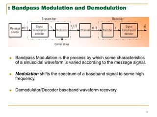
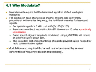
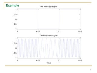
This document discusses bandpass modulation and demodulation techniques. It begins by defining bandpass modulation as varying characteristics of a sinusoidal carrier signal according to a message signal. This shifts the spectrum of the baseband signal to a higher frequency. A demodulator is then needed to recover the original baseband signal. The document goes on to explain why modulation is needed, such as to allow for practical antenna sizes in wireless communication. It also describes digital modulation techniques including amplitude shift keying (ASK), frequency shift keying (FSK), and phase shift keying (PSK). Mathematical expressions and diagrams are provided to illustrate these techniques.

![4
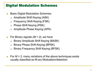
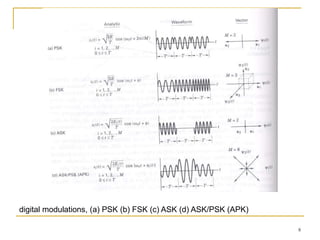
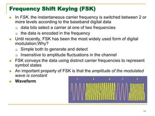
4.2 Digital Bandpass Modulation Techniques
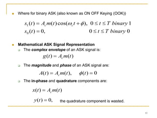
Three ways of representing bandpass signal:
(1) Magnitude and Phase (M & P)
Any bandpass signal can be represented as:
A(t) ≥ 0 is real valued signal representing the magnitude
Θ(t) is the genarlized angle
φ(t) is the phase
The representation is easy to interpret physically, but often is not
mathematically convenient
In this form, the modulated signal can represent information through
changing three parameters of the signal namely:
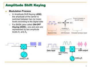
Amplitude A(t) : as in Amplitude Shift Keying (ASK)
Phase φ(t) : as in Phase Shift Keying (PSK)
Frequency dΘ(t)/ dt : as in Frequency Shift Keying (FSK)
)]
(
cos[
)
(
cos[
)
(
)
( 0 t
t
t
A
t
t
A
t
s
](https://image.slidesharecdn.com/eee3237-231112124913-576c5152/85/EEE323_7-pptx-4-320.jpg)
![15
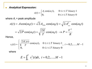
Analytical Expression
General expression is
Where
1
,....
1
,
0
),
cos(
2
)
(
M
i
t
T
E
t
s i
s
s
i
form
Analog
)
(
)
(
]
)
(
[
)
(
0
0
t
m
f
f
t
dt
d
f
d
m
t
t
d
i
i
t
d
i
b
s
b
s
i kT
T
kE
E
and
f
i
f
f
,
0
1
i
i f
f
f
1
,....
1
,
0
),
2
2
cos(
2
)
( 0
M
i
ft
i
t
f
T
E
t
s
s
s
i
](https://image.slidesharecdn.com/eee3237-231112124913-576c5152/85/EEE323_7-pptx-14-320.jpg)