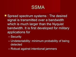
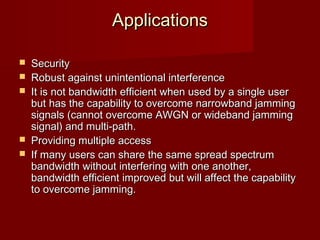
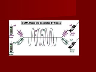
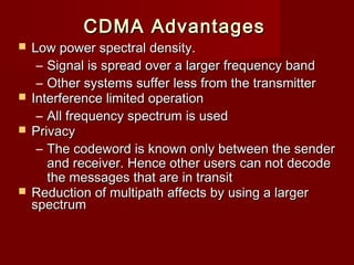
SSMA
 Spread Spectrum Multiple Access

                   AJAL.A.J
           Assistant Professor –Dept of ECE,
Federal Institute of Science And Technology (FISAT)   TM
                                                             
               MAIL: ec2reach@gmail.com
SSMA
 Spread spectrum systems : The desired
    signal is transmitted over a bandwidth
    which is much larger than the Nyquist
    bandwidth. It is first developed for military
    applications for
    – Security
    – Undetectability: minimum probability of being
      detected
    – Robust against intentional jammers
                   
Applications

   Security
   Robust against unintentional interference
   It is not bandwidth efficient when used by a single user
    but has the capability to overcome narrowband jamming
    signals (cannot overcome AWGN or wideband jamming
    signal) and multi-path.
   Providing multiple access
   If many users can share the same spread spectrum
    bandwidth without interfering with one another,
    bandwidth efficient improved but will affect the capability
    to overcome jamming.


Spread Spectrum Access
 Two techniques
    –   Frequency Hopped Multiple Access (FHMA)
    –   Direct Sequence Multiple Access (DSMA)
         Also called Code Division Multiple Access – CDMA


Frequency Hopping (FHMA)

 Digital muliple access technique
 A wideband radio channel is used.
    – Same wideband spectrum is used
   The carrier frequency of users are varied in a
    pseudo-random fashion.
     – Each user is using a narrowband channel
       (spectrum) at a specific instance of time.
     – The random change in frequency make the
       change of using the same narrowband channel
       very low.


Frequency Hopping (FHMA)
 The sender receiver change frequency
  (calling hopping) using the same pseudo-
  random sequence, hence they are
  synchronized.
 Rate of hopping versus Symbol rate
    – If hopping rate is greather: Called Fast
      Frequency Hopping
        One bit transmitted in multiple hops.
    – If symbol rate is greater: Called Slow Frequency
      Hopping
        Multiple bits are transmitted in a hopping period
        GSM and Bluetooth are example systems


Code Division Multiple Access
                (CDMA)
   In CDMA, the narrowband message signal is
    multiplied by a very large bandwidth signal called
    spreading signal (code) before modulation and
    transmission over the air. This is called spreading.

   CDMA is also called DSSS (Direct Sequence
    Spread Spectrum). DSSS is a more general term.

   Message consists of symbols
    – Has symbol period and hence, symbol rate
Code Division Multiple Access
                (CDMA)
   Spreading signal (code) consists of chips
    – Has Chip period and and hence, chip rate
    – Spreading signal use a pseudo-noise (PN) sequence (a pseudo-
      random sequence)
    – PN sequence is called a codeword
    – Each user has its own cordword
    – Codewords are orthogonal. (low autocorrelation)
    – Chip rate is oder of magnitude larger than the symbol rate.
   The receiver correlator distinguishes the senders signal
    by examining the wideband signal with the same time-
    synchronized spreading code
   The sent signal is recovered by despreading process at
    the receiver.
CDMA Advantages
 Low power spectral density.
   – Signal is spread over a larger frequency band
   – Other systems suffer less from the transmitter
 Interference limited operation
   – All frequency spectrum is used
 Privacy
   – The codeword is known only between the sender
     and receiver. Hence other users can not decode
     the messages that are in transit
 Reduction of multipath affects by using a larger
  spectrum
CDMA Advantages
   Random access possible
    – Users can start their transmission at any time
   Cell capacity is not concerete fixed like in TDMA
    or FDMA systems. Has soft capacity
   Higher capacity than TDMA and FDMA
   No frequency management
   No equalizers needed
   No guard time needed
   Enables soft handoff
CDMA Principle
                                                     Represent bit 1 with +1
                                                     Represent bit 0 with -1
           One bit period (symbol period)

                       1                                                        1
    Data
                                                         0

           1   1   1   0   1   0   1   1 1   1   1   0   1   0   1   1


Coded
Signal


                                                                          Chip period
  Input to the modulator (phase modulation)
Processing Gain
• Main parameter of CDMA is the processing gain
  that is defined as:
                                    Bspread       Bchip
                            Gp =              =
                                       R           R
                               Gp: processing gain
                               Bspread: PN code rate
                               Bchip: Chip rate
                               R: Data rate

 • IS-95 System (Narrowband CDMA) has a gain of 64. Other systems have gain between
   10 and 100.
    – 1.228 Mhz chipping rate
    – 1.25 MHz spread bandwidth
Near Far Problem and Power Control

• At a receiver, the signals
  may come from various            B   pr(M)
  (multiple sources.
   – The strongest signal
     usually captures the                      M
     modulator. The other
     signals are considered    M
     as noise
   – Each source may have
     different distances to        M
     the base station
                                               M
Near Far Problem and Power
              Control
   In CDMA, we want a base station to receive
    CDMA coded signals from various mobile
    users at the same time.
    – Therefore the receiver power at the base station
      for all mobile users should be close to eacother.
    – This requires power control at the mobiles.
   Power Control : Base station monitors the
    RSSI values from different mobiles and then
    sends power change commands to the
    mobiles over a forward channel. The mobiles
    then adjust their transmit power.
DSSS Transmitter
Message                 Baseband                            sss(t)
           +
  m(t)                    BPF                              Transmitted
               p(t)                                        Signal

      PN Code
      Generator                             Oscillator
                                               fc

      Chip Clock


                     2 Es
          sss (t ) =      m(t ) p (t ) cos(2πf c t + θ )
                      Ts
DSSS Receiver

                                         s1 (t )                         m(t )
           IF Wideband                             Phase Shift Keying
               Filter                                 Demodulator        Received
                                                                           Data
sss (t )                              p (t )
Received                        PN Code                Synchronization
DSSS Signal                     Generator                 System
at IF


                                   2 Es
                         s1 (t ) =      m(t ) cos(2πf c t + θ )
                                    Ts
Spectra of Received Signal
    Spectral         Interference     Spectral
    Density                           Density             Signal


                                                                   Interference


Signal


                         Frequency                             Frequency


          Output of Wideband filter              Output of Correlator after
                                                      dispreading,
                                                   Input to Demodulator
CDMA Example

                                  R     Receiver (a base station)


            Data=1011…                       Data=0010…


                   A                              B

        Transmitter (a mobile)              Transmitter
         Codeword=010011                 Codeword=101010


Data transmitted from A and B is multiplexed using CDMA and codeword.
The Receiver de-multiplexes the data using dispreading.
CDMA Example – transmission from two sources

    A Data
                          1                       0                           1                       1

   A          0 1     0       0   1   1   0 1     0   0   1   1 0     1   0   0   1   1   0   1   0       0   1   1
Codeword


Data ⊕ Code   1 0     1       1   0   0   0   1   0   0 1     1   1   0   1   1   0   0 1     0   1       1   0   0
 A Signal


    B Data                0                       0                           1                       0

              1   0   1       0   1   0   1   0   1   0   1   0 1     0   1   0   1   0   1   0   1       0   1   0
   B
Codeword
Data ⊕ Code   1   0   1       0   1   0   1   0   1   0   1   0   0   1   0   1   0   1 1     0   1       0   1   0
  B Signal

Transmitted
    A+B
   Signal
CDMA Example – recovering signal A at the receiver

      A+B
     Signal
    received


     A
 Codeword
     at
  receiver


(A + B) ∗ Code


  Integrator
    Output


Comparator
  Output           0               1                   0      0

                       Take the inverse of this to obtain A
CDMA Example – recovering signal B at the
                     receiver
      A+B
     Signal
    received

       B
   Codeword
       at
    receiver


(A + B) ∗ Code


   Integrator
     Output


 Comparator
   Output
                 1               1                   0      1

                     Take the inverse of this to obtain B
CDMA Example – using wrong codeword at the receiver

    A+B
   Signal
  received


   Wrong
 Codeword
  Used at
  receiver


 Integrator
   Output


Comparator
  Output       X                0                   1                1
              Noise
               Wrong codeword will not be able to decode the original data!
Hybrid Spread Spectrum
           Techniques
 FDMA/CDMA
 – Available wideband spectrum is frequency
   divided into number narrowband radio
   channels. CDMA is employed inside each
   channel.
 DS/FHMA
 – The signals are spread using spreading codes (direct
   sequence signals are obtained), but these signal are
   not transmitted over a constant carrier frequency;
   they are transmitted over a frequency hopping carrier
   frequency.
Hybrid Spread Spectrum Techniques
   Time Division CDMA (TCDMA)
    – Each cell is using a different spreading code (CDMA
      employed between cells) that is conveyed to the
      mobiles in its range.
    – Inside each cell (inside a CDMA channel), TDMA is
      employed to multiplex multiple users.
   Time Division Frequency Hopping
    – At each time slot, the user is hopped to a new
      frequency according to a pseudo-random hopping
      sequence.
    – Employed in severe co-interference and multi-path
      environments.
        Bluetooth and GSM are using this technique.
Capacity of CDMA Systems

• Uplink Single-cell System Model
                User 2                                 Assumptions
                                                 • Total active users Ku
                                                 • The intra-cell MAI can be
                         ...
                                                   modeled as AWGN
 User 1                                 User k   • Perfect power control is
                                                 assumed
          .                        .             • Random sequences
          .                        .
          .                        .


                  ...          User n
    User Ku
Capacity of CDMA Systems
     Coarse estimate of the reverse link (uplink) capacity
         Assumptions:
              Single Cell.
              The interference caused by other users in the cell can be
               modeled as AWGN.
              Perfect power control is used, i.e. the received power of
               each user at the base station is the same.
         If the received power of each user is Ps watts, and the background
          noise can be ignored (ex: micro-cells), then the total interference
          power (MAI) at the output of the desired user’s detector is

          where Ku is the total number of equal energy users in the cell.
          Suppose each user can operate against Gaussian noise at a bit-
          energy-to-noise density level of Eb/Io. Let W be the entire spread
          bandwidth, then the interference spectral density can be expressed
          as:


          I ≅ ( K u − 1) Ps             I0 =
                                               I
                                                    Watts / Hz (one − sided )
                                               W
Capacity of CDMA Systems

                {
                                                      Ps
                    Also, the bit energy Eb is Eb =
 Interference                                         Rb
    limited                          I I ⋅W W Rb
                    Thus,   K u −1 = = 0        =
                                    Ps E b ⋅ R b E b I 0

★Now, if we consider the factors of voice activity (G v), sectorized
antenna gain (GA), and other-cell interface factor (f), where
Gv ≈ 1/v = 2.67
GA (three sectors) ≅ 2.4
f = (Interference form other cells)/(Interference from given cell) ≅ 0.6
Capacity of CDMA Systems
                      W R b Gv ⋅ GA
  In this case, Ku u ≅ be approximated by
                 K can        ⋅
                       E b I 0 (1 + f )


                         4 ⋅ (W R )
  Ex: If Gv ≅ 2.67, GA ≅ 2.4, f ≅ b0.6
                ⇒ Ku ≅
                            ( Eb   Io )


  If (Eb/Io) required is 6 dB (i.e. Eb/Io = 4)
                             W
                  ⇒ Ku ≅
                             Rb


  which will be larger than the TDMA or FDMA systems in the cellular
  environment.
SDMA
•   Use spot beam antennas
•    The different beam area can use TDMA, FDMA, CDMA
•    Sectorized antenna can be thought of as a SDMA
•    Adaptive antennas can be used in the future
    (simultaneously steer energy
in the direction of many users)


                                   spot beam
                                    antenna
Features:

 A large number of independently steered
  high-gain beams can be formed without
  any resulting degradation in SNR ratio.
 Beams can be assigned to individual
  users, thereby assuring that all links
  operate with maximum gain.
 Adaptive beam forming can be easily
  implemented to improve the system
  capacity by suppressing co channel
  interference.

Ssma

  • 1.
    SSMA Spread SpectrumMultiple Access AJAL.A.J Assistant Professor –Dept of ECE, Federal Institute of Science And Technology (FISAT) TM    MAIL: ec2reach@gmail.com
  • 2.
    SSMA  Spread spectrumsystems : The desired signal is transmitted over a bandwidth which is much larger than the Nyquist bandwidth. It is first developed for military applications for – Security – Undetectability: minimum probability of being detected – Robust against intentional jammers    
  • 3.
    Applications  Security  Robust against unintentional interference  It is not bandwidth efficient when used by a single user but has the capability to overcome narrowband jamming signals (cannot overcome AWGN or wideband jamming signal) and multi-path.  Providing multiple access  If many users can share the same spread spectrum bandwidth without interfering with one another, bandwidth efficient improved but will affect the capability to overcome jamming.    
  • 4.
    Spread Spectrum Access Two techniques – Frequency Hopped Multiple Access (FHMA) – Direct Sequence Multiple Access (DSMA)  Also called Code Division Multiple Access – CDMA    
  • 5.
    Frequency Hopping (FHMA) Digital muliple access technique  A wideband radio channel is used. – Same wideband spectrum is used  The carrier frequency of users are varied in a pseudo-random fashion. – Each user is using a narrowband channel (spectrum) at a specific instance of time. – The random change in frequency make the change of using the same narrowband channel very low.    
  • 6.
    Frequency Hopping (FHMA) The sender receiver change frequency (calling hopping) using the same pseudo- random sequence, hence they are synchronized.  Rate of hopping versus Symbol rate – If hopping rate is greather: Called Fast Frequency Hopping  One bit transmitted in multiple hops. – If symbol rate is greater: Called Slow Frequency Hopping  Multiple bits are transmitted in a hopping period    GSM and Bluetooth are example systems  
  • 7.
       
  • 8.
       
  • 9.
    Code Division MultipleAccess (CDMA)  In CDMA, the narrowband message signal is multiplied by a very large bandwidth signal called spreading signal (code) before modulation and transmission over the air. This is called spreading.  CDMA is also called DSSS (Direct Sequence Spread Spectrum). DSSS is a more general term.  Message consists of symbols – Has symbol period and hence, symbol rate
  • 10.
    Code Division MultipleAccess (CDMA)  Spreading signal (code) consists of chips – Has Chip period and and hence, chip rate – Spreading signal use a pseudo-noise (PN) sequence (a pseudo- random sequence) – PN sequence is called a codeword – Each user has its own cordword – Codewords are orthogonal. (low autocorrelation) – Chip rate is oder of magnitude larger than the symbol rate.  The receiver correlator distinguishes the senders signal by examining the wideband signal with the same time- synchronized spreading code  The sent signal is recovered by despreading process at the receiver.
  • 11.
    CDMA Advantages  Lowpower spectral density. – Signal is spread over a larger frequency band – Other systems suffer less from the transmitter  Interference limited operation – All frequency spectrum is used  Privacy – The codeword is known only between the sender and receiver. Hence other users can not decode the messages that are in transit  Reduction of multipath affects by using a larger spectrum
  • 12.
    CDMA Advantages  Random access possible – Users can start their transmission at any time  Cell capacity is not concerete fixed like in TDMA or FDMA systems. Has soft capacity  Higher capacity than TDMA and FDMA  No frequency management  No equalizers needed  No guard time needed  Enables soft handoff
  • 13.
    CDMA Principle Represent bit 1 with +1 Represent bit 0 with -1 One bit period (symbol period) 1 1 Data 0 1 1 1 0 1 0 1 1 1 1 1 0 1 0 1 1 Coded Signal Chip period Input to the modulator (phase modulation)
  • 14.
    Processing Gain • Mainparameter of CDMA is the processing gain that is defined as: Bspread Bchip Gp = = R R Gp: processing gain Bspread: PN code rate Bchip: Chip rate R: Data rate • IS-95 System (Narrowband CDMA) has a gain of 64. Other systems have gain between 10 and 100. – 1.228 Mhz chipping rate – 1.25 MHz spread bandwidth
  • 15.
    Near Far Problemand Power Control • At a receiver, the signals may come from various B pr(M) (multiple sources. – The strongest signal usually captures the M modulator. The other signals are considered M as noise – Each source may have different distances to M the base station M
  • 16.
    Near Far Problemand Power Control  In CDMA, we want a base station to receive CDMA coded signals from various mobile users at the same time. – Therefore the receiver power at the base station for all mobile users should be close to eacother. – This requires power control at the mobiles.  Power Control : Base station monitors the RSSI values from different mobiles and then sends power change commands to the mobiles over a forward channel. The mobiles then adjust their transmit power.
  • 17.
    DSSS Transmitter Message Baseband sss(t) + m(t) BPF Transmitted p(t) Signal PN Code Generator Oscillator fc Chip Clock 2 Es sss (t ) = m(t ) p (t ) cos(2πf c t + θ ) Ts
  • 18.
    DSSS Receiver s1 (t ) m(t ) IF Wideband Phase Shift Keying Filter Demodulator Received Data sss (t ) p (t ) Received PN Code Synchronization DSSS Signal Generator System at IF 2 Es s1 (t ) = m(t ) cos(2πf c t + θ ) Ts
  • 19.
    Spectra of ReceivedSignal Spectral Interference Spectral Density Density Signal Interference Signal Frequency Frequency Output of Wideband filter Output of Correlator after dispreading, Input to Demodulator
  • 20.
    CDMA Example R Receiver (a base station) Data=1011… Data=0010… A B Transmitter (a mobile) Transmitter Codeword=010011 Codeword=101010 Data transmitted from A and B is multiplexed using CDMA and codeword. The Receiver de-multiplexes the data using dispreading.
  • 21.
    CDMA Example –transmission from two sources A Data 1 0 1 1 A 0 1 0 0 1 1 0 1 0 0 1 1 0 1 0 0 1 1 0 1 0 0 1 1 Codeword Data ⊕ Code 1 0 1 1 0 0 0 1 0 0 1 1 1 0 1 1 0 0 1 0 1 1 0 0 A Signal B Data 0 0 1 0 1 0 1 0 1 0 1 0 1 0 1 0 1 0 1 0 1 0 1 0 1 0 1 0 B Codeword Data ⊕ Code 1 0 1 0 1 0 1 0 1 0 1 0 0 1 0 1 0 1 1 0 1 0 1 0 B Signal Transmitted A+B Signal
  • 22.
    CDMA Example –recovering signal A at the receiver A+B Signal received A Codeword at receiver (A + B) ∗ Code Integrator Output Comparator Output 0 1 0 0 Take the inverse of this to obtain A
  • 23.
    CDMA Example –recovering signal B at the receiver A+B Signal received B Codeword at receiver (A + B) ∗ Code Integrator Output Comparator Output 1 1 0 1 Take the inverse of this to obtain B
  • 24.
    CDMA Example –using wrong codeword at the receiver A+B Signal received Wrong Codeword Used at receiver Integrator Output Comparator Output X 0 1 1 Noise Wrong codeword will not be able to decode the original data!
  • 25.
    Hybrid Spread Spectrum Techniques  FDMA/CDMA – Available wideband spectrum is frequency divided into number narrowband radio channels. CDMA is employed inside each channel.  DS/FHMA – The signals are spread using spreading codes (direct sequence signals are obtained), but these signal are not transmitted over a constant carrier frequency; they are transmitted over a frequency hopping carrier frequency.
  • 26.
    Hybrid Spread SpectrumTechniques  Time Division CDMA (TCDMA) – Each cell is using a different spreading code (CDMA employed between cells) that is conveyed to the mobiles in its range. – Inside each cell (inside a CDMA channel), TDMA is employed to multiplex multiple users.  Time Division Frequency Hopping – At each time slot, the user is hopped to a new frequency according to a pseudo-random hopping sequence. – Employed in severe co-interference and multi-path environments.  Bluetooth and GSM are using this technique.
  • 27.
    Capacity of CDMASystems • Uplink Single-cell System Model User 2 Assumptions • Total active users Ku • The intra-cell MAI can be ... modeled as AWGN User 1 User k • Perfect power control is assumed . . • Random sequences . . . . ... User n User Ku
  • 28.
    Capacity of CDMASystems  Coarse estimate of the reverse link (uplink) capacity  Assumptions:  Single Cell.  The interference caused by other users in the cell can be modeled as AWGN.  Perfect power control is used, i.e. the received power of each user at the base station is the same.  If the received power of each user is Ps watts, and the background noise can be ignored (ex: micro-cells), then the total interference power (MAI) at the output of the desired user’s detector is where Ku is the total number of equal energy users in the cell. Suppose each user can operate against Gaussian noise at a bit- energy-to-noise density level of Eb/Io. Let W be the entire spread bandwidth, then the interference spectral density can be expressed as: I ≅ ( K u − 1) Ps I0 = I Watts / Hz (one − sided ) W
  • 29.
    Capacity of CDMASystems { Ps Also, the bit energy Eb is Eb = Interference Rb limited I I ⋅W W Rb Thus, K u −1 = = 0 = Ps E b ⋅ R b E b I 0 ★Now, if we consider the factors of voice activity (G v), sectorized antenna gain (GA), and other-cell interface factor (f), where Gv ≈ 1/v = 2.67 GA (three sectors) ≅ 2.4 f = (Interference form other cells)/(Interference from given cell) ≅ 0.6
  • 30.
    Capacity of CDMASystems W R b Gv ⋅ GA In this case, Ku u ≅ be approximated by K can ⋅ E b I 0 (1 + f ) 4 ⋅ (W R ) Ex: If Gv ≅ 2.67, GA ≅ 2.4, f ≅ b0.6 ⇒ Ku ≅ ( Eb Io ) If (Eb/Io) required is 6 dB (i.e. Eb/Io = 4) W ⇒ Ku ≅ Rb which will be larger than the TDMA or FDMA systems in the cellular environment.
  • 31.
    SDMA • Use spot beam antennas • The different beam area can use TDMA, FDMA, CDMA • Sectorized antenna can be thought of as a SDMA • Adaptive antennas can be used in the future (simultaneously steer energy in the direction of many users) spot beam antenna
  • 32.
    Features:  A largenumber of independently steered high-gain beams can be formed without any resulting degradation in SNR ratio.  Beams can be assigned to individual users, thereby assuring that all links operate with maximum gain.  Adaptive beam forming can be easily implemented to improve the system capacity by suppressing co channel interference.