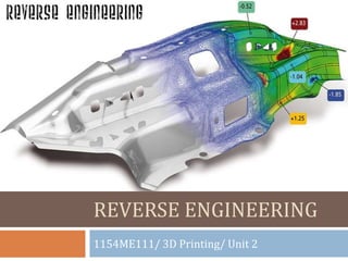

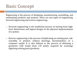
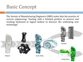
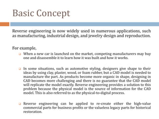
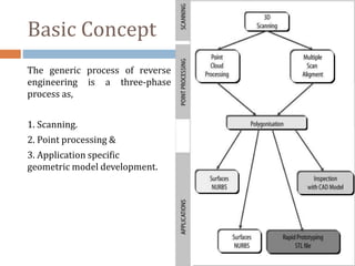
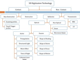
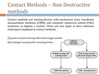
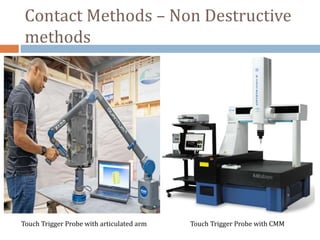
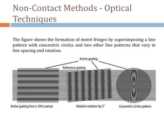


The document discusses reverse engineering, which involves duplicating an existing part without documentation by working backwards from the finished product. There are two main types of engineering: forward engineering, which moves from design to implementation, and reverse engineering. Reverse engineering has various applications and involves a three-phase process of scanning the object, processing the scan data, and developing a geometric model. Common scanning techniques include contact methods using probes and non-contact methods like laser scanning.


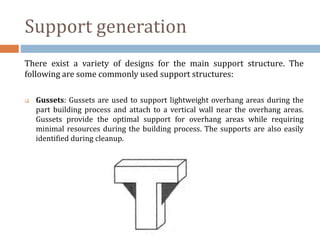
![[Deck] What's New in Spark-Iceberg Integration via DSV2.pptx](https://cdn.slidesharecdn.com/ss_thumbnails/deckwhatsnewinspark-icebergintegrationviadsv2-260210005337-25955b12-thumbnail.jpg?width=640&height=640&fit=bounds)


