Download as PDF, PPTX

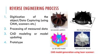
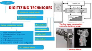
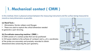
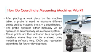
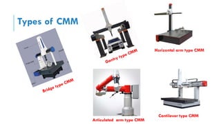
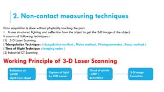
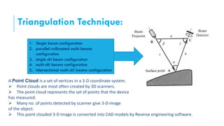
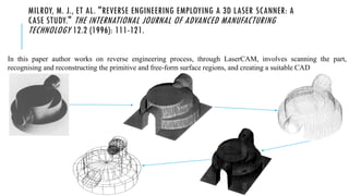
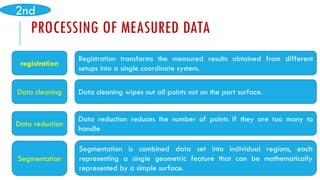
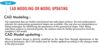
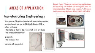


Reverse engineering is a systematic process of analyzing existing systems or products to understand their design or redesign them. It involves creating CAD models from physical objects using techniques like 3D laser scanning or CT scanning. Reverse engineering has applications in new product design, redesign of existing products, custom product design, and modifying physical models. It is an efficient approach to significantly reduce product development time by optimizing available resources and meeting customer requirements. The reverse engineering process includes data capturing, processing measured data, CAD modeling, and creating prototypes. Common digitizing techniques are contact methods using CMM and non-contact methods like laser scanning and CT scanning.


