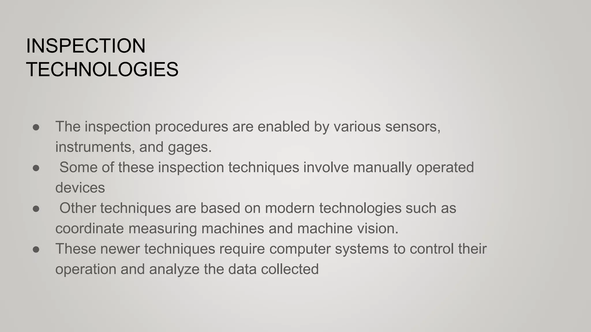
This document discusses various inspection principles, practices, and technologies. It begins by describing inspection techniques that are either manual or rely on modern machines like CMMs. Key aspects of metrology and desirable instrument characteristics are outlined. The document then differentiates between contact and non-contact inspection, noting advantages of non-contact methods. Specific technologies are examined, including CMMs, machine vision, optical tools, and non-optical techniques using other sensor types.
The document discusses various mechanical energy based machining processes including abrasive jet machining, water jet machining, abrasive water jet machining, ultrasonic machining, and their working principles. It provides details of each process such as their mechanism of material removal, advantages, disadvantages, applications, and parameters that affect the processes. Key processes covered are abrasive jet machining which uses a high velocity jet of abrasive particles to erode material, water jet machining which uses a high pressure water jet, and ultrasonic machining which uses abrasive particles vibrated at ultrasonic frequencies to machine hard brittle materials.
Honing is an abrasive machining process that produces a precision surface on a metal work piece by scrubbing an abrasive stone against it along a controlled path.
Honing is primarily used to improve the geometric form of a surface, but may also improve the surface texture.
This document discusses various sheet metal forming processes including cutting, bending, drawing and other operations. It defines sheet metalworking as including cutting and forming thin sheets of metal between 0.4mm to 6mm thick. Common sheet metal forming processes are described as shearing, blanking, punching, bending and drawing. Factors involved in sheet metal cutting like clearance, punch and die sizes, and estimating cutting forces are also summarized.
Sheet metal is a thin piece of metal between 0.006 and 0.25 inches thick. Sheet metal can be cut, bent, and stretched into various shapes through forming and cutting operations. Common forming operations include bending, deep drawing, and roll forming. Common cutting operations include shearing, blanking, punching, notching, and slitting. Sheet metal workers use tools like dies and presses to perform these operations and shape the metal.
Plasma arc machining uses ionized gas (plasma) to cut metals. It can cut materials that are difficult to cut with traditional techniques due to high thermal conductivity and oxidation resistance. The process involves generating a pilot arc to ignite the plasma and transferring the arc to the workpiece to melt and vaporize the metal, which is removed by the high-velocity gas. Plasma arc machining produces high-quality cuts at maximum productivity and is suitable for automated cutting applications.
This chapter aims to provide basic backgrounds of different types of machining processes and highlights on an understanding of important parameters which affects machining of metals with their chip removals.
Metal cutting or Machining is the process of producing workpiece by removing unwanted material from a block of metal. in the form of chips. This process is most important since almost all the products get their final shape and size by metal removal. either directly or indirectly.
The major drawback of the process is loss of material in the form of chips. In this chapter. we shall have a fundamental understanding of the basic metal process.
Part programming involves writing a sequence of instructions for a NC/CNC machine to produce a component. There are two types of part programming: manual and computer-aided. The programmer decides the machining operations and tooling. A part program includes steps like preparing a process plan, selecting tools, determining parameters, and writing the program. The program uses codes like G-codes for motions and functions, M-codes for modes, and N-codes to identify blocks. Data is arranged in blocks that can have different formats. Interpolation methods like linear and circular are used to machine between points.
The document discusses the mechanics of metal cutting. It covers topics such as cutting models, turning forces, power and energies, tool terminology, cutting geometry, material removal rate, orthogonal and oblique cutting models, turning and facing forces, velocities, cutting forces, the merchant's circle diagram, stresses, power, specific cutting energy, and violations of orthogonal cutting models. It provides the theoretical framework for understanding metal cutting and machining processes.
This document summarizes various surface treatment techniques including mechanical processes like shot peening and deep rolling that modify the surface without changing chemistry, thermal processes like electron beam treatment and laser treatment, and thermo-chemical processes like carburizing, nitriding, and carbonitriding that diffuse elements like carbon or nitrogen into the surface. It provides details on the mechanisms, advantages, and applications of these different surface modification methods.
The document discusses three mechanical energy-based machining processes: abrasive jet machining (AJM), water jet machining (WJM), and ultrasonic machining (USM). In AJM, a high-speed stream of abrasive particles erodes material from the workpiece. WJM uses a high-velocity water jet to convert kinetic energy into pressure that removes small chips. USM forces an abrasive slurry against the workpiece using a vibrating tool to remove extremely small chips. Key parameters for each process include abrasive properties, pressure, velocity, vibration frequency, and more. Each method can machine hard materials and provides advantages like avoiding heat, being noiseless, or enabling intricate shapes.
The document provides an overview of CNC machine training presented by Tarun B Patel. It includes an introduction to CNC, the constructional features of CNC machines, programming formats and codes, and a demonstration of a vertical machining center. The objective is to familiarize trainees with the VMC and how to maintain it. The presentation covers the specification, elements, operations, and programming of the VMC used in the demonstration. Sample part programs are also included to illustrate linear, circular and canned cycle operations.
The document discusses various metal forming processes including hot working and cold working of metals. It describes processes like forging, rolling, extrusion, drawing, and spinning. Forging can be done through open die forging or closed die forging using various machines. It involves operations like upsetting, drawing down, punching, bending, and forging welding. Rolling involves processes like flat rolling and shape rolling. Extrusion can be done through hot or cold working. The document compares the characteristics and advantages and limitations of hot working versus cold working of metals.
Ultrasonic machining (USM) involves removing material from a workpiece using high-frequency vibrations and an abrasive slurry. Key components of USM include a generator, transducer, horn, tool, abrasive slurry, and workpiece. The main material removal mechanisms are mechanical abrasion, impact, erosion, and chemical effects. USM can machine hard and brittle materials like ceramics and has advantages like avoiding thermal/mechanical damage but has limitations like lower material removal rates compared to other processes. Process parameters that influence the material removal rate include amplitude, frequency, abrasive size, and slurry properties.
This document discusses different types of geometric modeling methods including wireframe, surface, and solid modeling. Wireframe modeling uses points and lines to define objects but does not represent actual surfaces or volumes. Surface modeling defines the outer surfaces of an object. Solid modeling precisely defines the enclosed volume of an object using its faces, edges, and vertices. Constructive solid geometry and boundary representation are two common solid modeling techniques. CSG uses Boolean operations to combine primitive shapes, while boundary representation stores topological information about faces, edges, and vertices. Feature-based modeling allows shapes to be created through operations like extruding, revolving, sweeping, and filling.
Rapid prototyping technologies allow engineers to create physical prototypes of designs prior to full production. The document discusses the rapid prototyping process which involves:
1. Creating a CAD model and converting it to STL format.
2. Slicing the STL file into thin layers and constructing the prototype layer-by-layer using different techniques like stereolithography, selective laser sintering, or fused deposition modeling.
3. Post-processing the prototype by removing supports, cleaning, and finishing the surface.
Specific rapid prototyping methods like stereolithography, selective laser sintering, and fused deposition modeling are described in detail. The document also discusses applications and limitations of rapid
Electro-chemical machining (ECM) is a non-traditional machining process that removes metal by dissolving it in an electrolyte with the use of electric current. In ECM, the workpiece acts as an anode and is dissolved by the electrolyte, while a tool with the desired shape acts as a cathode. Key factors in ECM include the electrolyte, which carries current and removes dissolved material, the tool and workpiece materials, and a DC power supply. ECM can machine hard metals and complex shapes with high accuracy and no tool wear. Common applications of ECM include machining turbine blades, aerospace components, and other difficult-to-machine metals.
Electrochemical machining (ECM) is a non-traditional machining process that removes metal by electrolysis rather than mechanical forces. In ECM, a tool acts as a cathode and the workpiece as an anode, and an electric current is passed through an electrolyte in the gap between them, chemically dissolving metal from the workpiece. ECM can machine hard metals and complex shapes more accurately than traditional machining. It provides a smooth surface finish with no mechanical forces or heat affecting the workpiece material. However, ECM requires an electrolyte solution, specialized equipment, and produces chemical waste, making it more expensive and less environmentally friendly than other processes.
Electrochemical grinding (ECG) is a process where a rotating grinding wheel acts as a cathode and the workpiece is the anode. An electrolyte like NaNO3 is used and a voltage is applied, causing material to be removed from the workpiece electrochemically with some additional removal by abrasion from diamond or aluminum oxide particles on the wheel. ECG can machine difficult materials, achieve close tolerances on thin parts without distortion, and offers advantages over conventional grinding like higher removal rates and elimination of burrs. However, it also has higher costs and is limited to electrically conductive materials.
Gear finishing processes are necessary to produce accurate, smooth gear teeth after initial formation. The main gear finishing processes are gear shaving, burnishing, grinding, lapping, and honing. Gear shaving involves running a gear against a cutter to scrape off irregularities. Gear burnishing plastically moves excess material during rolling. Gear grinding is the most accurate but also the most expensive method. Lapping and honing use abrasives to remove burrs and irregularities from heat treated gears in a faster process than other methods.
Micro Plasma welding is used for precision welding of small components . It is a advanced welding process and can be easily automated . It can maintain a arc at a current as low as 0.1 amp and can weld sheets as this as 100 microns .
This document provides an overview of mechanical energy based unconventional machining processes. It discusses abrasive jet machining (AJM), water jet machining (WJM), and ultrasonic machining (USM). For each process, it describes the basic working principles, key components, process parameters that influence material removal rate, advantages, disadvantages, and applications. It also compares different types of transducers used in USM and discusses factors affecting the machining performance of USM.
The document discusses various non-traditional machining processes such as abrasive jet machining (AJM), water jet machining (WJM), and ultrasonic machining (USM). It provides details on the classification of non-traditional processes, including mechanical metal removal processes, electro-chemical processes, and thermal methods. Specific information on process parameters and applications are given for AJM, WJM, and USM. The advantages and limitations of these non-traditional machining techniques are also summarized.
Computer assisted part programming uses APT (Automatically Programmed Tool) language to define part geometry and tool paths to machine complex parts. The programmer first defines points, lines, circles, and planes representing the part geometry. Then tool paths are specified using motion commands like GOTO for point-to-point and GO/TO for continuous contouring motions along the defined geometry. Postprocessor statements control machine functions and auxiliary statements name the program and insert comments.
The document summarizes the rolling process. It defines rolling as plastically deforming metal by passing it between rolls. Rolling provides close dimensional control and high production. There are two main types: hot rolling and cold rolling. The document describes various rolling terminologies, mill products, defects, and different rolling processes like hot rolling, cold rolling, shaped rolling, and thread rolling. It also discusses factors like angle of contact, forces involved, and how to control flatness.
This document provides an overview of computer numerical control (CNC) machines. It discusses the history and evolution of CNC, the key elements and programming of CNC machines, and their advantages over manual machines. CNC machines automate manufacturing processes by using computer code to control machine tools and automate cutting, shaping, and assembly. They offer benefits like easier programming, storage of programs, avoidance of human errors, and ability to produce complex parts as cheaply as simple ones.
CNC machines use computer programs and numeric control to operate machine tools like milling machines and lathes. Key features include automated tool changes and multi-axis movement controlled by motors. CNC programming involves specifying coordinates, feed rates, spindle speeds, and preparatory codes like G-codes for different motions and functions. Programs are debugged to ensure accurate machining based on part designs.
Selective Laser Sintering is one of the most used processes of Rapid Prototyping. It is a powder based process where powder of different metals/materials get sintered by LASER.
COMPUTER AIDED QUALITY CONTROL AND HANDLING SYSTEMS.pptxDr.M BALA THEJA
COMPUTER AIDED QUALITY CONTROL AND HANDLING SYSTEMS
Inspection is normally used to examine whether a product conforms to the design standards specified for it. For a mechanical component, this would be probably concerned with the dimensions, surface texture and tolerances specified for the part. Non-conforming goods result in scrap, rework, and the loss of customer goodwill
APPLICATION OF MECHATRONICS IN COORDINATE MEASURING MACHINE.USE OF MULTI-SENSOR TECHNOLOGY.CMM IS USED TO MEASURE COORDINATE OF A WORKPIECE WITH THE HELP OF PROBE.CMM CAN BE CONTROLLED WITH THE HELP OF NUMERICAL CONTROL. INTRODUCTION TO 5 AXIS TECHNOLOGY.
ADVANTAGES OF CMM.TYPES OF CMM.
Coordinate metrology is concerned with the measurement of the actual shape and dimensions of an object and comparing these with the desired shape and dimensions.
In this connection, coordinate metrology consists of the evaluation of the location, orientation, dimensions, and geometry of the part or object.
A Coordinate Measuring Machine (CMM) is an electromechanical system designed to perform coordinate metrology.
Precision measurement technology and application based on machine visionIJRES Journal
Presently, the precision measurement technology based on machine vision has applied to all kinds of fields such as electron, motorcar, weave, glass and metalworking. It can also work effectively in many occasions that many old methods are difficult to check and measure. The levels of production automation and intelligent detection system have been improved greatly. In this paper, the basic principle and application of the machine vision system is introduced firstly, and then the application of small modulus gear precision measurement technology based on machine vision is taken as an example to show the feasibility of this method in precision measurement. The results revealed the advantages of machine vision method that the measurement efficiency is improved and the artificial error is reduced.
The document discusses different types of probing systems used on coordinate measuring machines (CMMs). It describes various probes, including tactile and non-contact probes, and their applications. Common probes include touch-trigger, scanning, and continuous probes. Factors like part geometry, required measurements, accuracy, and throughput influence the selection of probing systems. CMMs provide advantages over manual inspection like reduced inspection time, flexibility, and precision.
The document discusses reverse engineering, which involves duplicating an existing part without documentation by working backwards from the finished product. There are two main types of engineering: forward engineering, which moves from design to implementation, and reverse engineering. Reverse engineering has various applications and involves a three-phase process of scanning the object, processing the scan data, and developing a geometric model. Common scanning techniques include contact methods using probes and non-contact methods like laser scanning.
Photogrammetry is a scientific method that uses photography to reconstruct the 3D form and spatial position of objects from photographs. It involves acquiring images of an object from different positions and then using software to detect targets in the images and compute precise 3D coordinates. ICam systems are portable photogrammetry systems that employ triangulation to measure 3D coordinates of points on an object contactlessly using a digital camera, coded targets, and processing software. ICam offers high measurement accuracy down to 0.005mm and is suited for applications like inspection, deformation analysis, and crash testing.
This document discusses coordinate measuring machines (CMMs). It describes the different types of CMM mechanical structures including cantilever, moving bridge, fixed bridge, horizontal arm, gantry, and column types. It also discusses CMM components, probe types, calibration, programming, applications, advantages, and sources of errors. CMMs are used to precisely measure the geometry of manufactured parts for quality control.
The document discusses reverse engineering techniques. It describes reverse engineering as generating a CAD model from an existing physical part to reconstruct it. There are contact-based methods like coordinate measuring machines and non-contact methods like 3D scanners. 3D scanners use light or lasers to scan objects and generate CAD designs without contact. Reverse engineering is used to manufacture replacement parts, redesign products lacking documentation, or create cheaper alternatives.
Reverse engineering is the process of analyzing an existing system or product to identify its components and design in order to extract design details without prior documentation. It involves digitizing a physical object using 3D scanning techniques like contact methods, non-contact active methods, and non-contact passive methods to obtain point cloud data. This point cloud data is then processed to generate CAD models through techniques like polygonization and refinement. The final CAD models can then be used for applications like redesign, quality control, and rapid prototyping.
The document discusses different measurement technologies that can meet the increasing inspection requirements of high-production turning equipment. Non-contact turned part measuring centers like the Tesascan can automatically inspect small dental implants. Vision systems provide significant throughput advantages over manual inspection for parts like piston valves. Touch probe systems allow inspection of turned and milled contours directly on the machine for the highest throughput.
What is Dimensional Metrology? Dimensional Metrology Machine Types.pdfVIEW
Dimensional metrology is the science of calibrating and using measurement equipment to quantify the physical size and shape of objects. This field encompasses a wide range of techniques and tools designed to measure dimensions such as length, width, height, and geometric features like angles and radii.
Tool monitoring, First research step, AmirKabir University of Technology
www.linkedin.com/in/sajjad-ahmadpoor
https://twitter.com/zuzu0045
ssahmadpoor@aut.ac.ir
Automated Laser Scanning System For Reverse Engineering And InspectionJennifer Daniel
This document summarizes an automated laser scanning system developed for reverse engineering and inspection of parts with freeform surfaces. The system generates optimal scan plans considering parameters like view angle, depth of field, and occlusion. It uses a laser scanner mounted on a motorized rotary table to automatically scan parts according to the generated scan plans. The point data is then automatically registered and evaluated by comparing to CAD models. The system aims to automate the scanning process for more efficient inspection and reverse engineering of complex parts.
Machine Vision System for Inspecting Flank Wear on Cutting ToolsIDES Editor
This paper describes the development of a machine
vision system for automated tool wear inspection. The proposed
approach measures the tool wear region based on the active
contour algorithm and classifies the wear type by means of
neural networks. Test results show that prevalent tool wears
can be checked robustly in a real production environment and
therefore the manufacturing automation can be improved.
Measurement techniques in micro machining PDF by badebhau4@gmail.comEr. Bade Bhausaheb
This document discusses various measurement techniques used in micro machining. It begins by explaining the need for developing new measurement techniques capable of accurately measuring micro-scale features between 0.1 to 100 μm. It then categorizes measuring systems as either dimensional or topographic and describes examples in each category. Key techniques discussed include optical microscopes, electron microscopes like SEM, interferometers, profilometers, scanning probe microscopes and laser-based systems. The document provides details on operating principles, applications, accuracy and resolution limits of these micro-measurement techniques.
Disturbance Observer And Optimal Fuzzy Controllers Used In Controlling Force ...theijes
The International Journal of Engineering & Science is aimed at providing a platform for researchers, engineers, scientists, or educators to publish their original research results, to exchange new ideas, to disseminate information in innovative designs, engineering experiences and technological skills. It is also the Journal's objective to promote engineering and technology education. All papers submitted to the Journal will be blind peer-reviewed. Only original articles will be published.
This document discusses coordinate measuring machines (CMMs), which are metrological instruments used to measure physical and geometric characteristics of objects. CMMs can be manually controlled by an operator or computer controlled. Measurements are made by touching the object's surface with an attached probe. CMMs play an important role in quality control for industries like aerospace, automotive, and healthcare. They are well-suited for short production runs with multiple features due to their flexibility. Common CMM configurations include moving bridge, fixed bridge, column, horizontal arm, and gantry styles. Modes of operation range from manual to direct computer control. Probes can be contact-based or non-contact laser/video probes. CMM
This document provides information about CNC (Computer Numerical Control) machines. It discusses:
- The components of a numerical control (NC) system, including the part program, machine control unit, and processing equipment.
- The differences between traditional NC, CNC, and DNC machines. CNC machines have their own onboard computers while DNC machines are networked.
- Types of motion control systems like point-to-point positioning and continuous path/contouring. Interpolation methods including linear and circular are described.
- Open loop and closed loop control systems. Closed loop provides feedback to check if commanded positions are achieved.
Similar to Inspection Principles and practices, Inspection technologies.pptx (20)
How to Setup Default Value for a Field in Odoo 17Celine George
In Odoo, we can set a default value for a field during the creation of a record for a model. We have many methods in odoo for setting a default value to the field.
Level 3 NCEA - NZ: A Nation In the Making 1872 - 1900 SML.pptHenry Hollis
The History of NZ 1870-1900.
Making of a Nation.
From the NZ Wars to Liberals,
Richard Seddon, George Grey,
Social Laboratory, New Zealand,
Confiscations, Kotahitanga, Kingitanga, Parliament, Suffrage, Repudiation, Economic Change, Agriculture, Gold Mining, Timber, Flax, Sheep, Dairying,
Gender and Mental Health - Counselling and Family Therapy Applications and In...PsychoTech Services
A proprietary approach developed by bringing together the best of learning theories from Psychology, design principles from the world of visualization, and pedagogical methods from over a decade of training experience, that enables you to: Learn better, faster!
How to Download & Install Module From the Odoo App Store in Odoo 17Celine George
Custom modules offer the flexibility to extend Odoo's capabilities, address unique requirements, and optimize workflows to align seamlessly with your organization's processes. By leveraging custom modules, businesses can unlock greater efficiency, productivity, and innovation, empowering them to stay competitive in today's dynamic market landscape. In this tutorial, we'll guide you step by step on how to easily download and install modules from the Odoo App Store.
2. INSPECTION
TECHNOLOGIES
● The inspection procedures are enabled by various sensors,
instruments, and gages.
● Some of these inspection techniques involve manually operated
devices
● Other techniques are based on modern technologies such as
coordinate measuring machines and machine vision.
● These newer techniques require computer systems to control their
operation and analyze the data collected
3. INSPECTION
METROLOGY
● Metrology is the science of measurement.
● Measurement is defined as a procedure in which an unknown quantity
is compared to a known standard, using an accepted and consistent
system of units.
● Two aspects of a standard are critical:
(1) it must be constant, not changing over time.
(2)it must be based on a system of units that is consistent and
accepted by users.
4. CHARACTERISTICS OF MEASURING
INSTRUMENTS
● Accuracy is the degree to which the measured value agrees with the true
value of the quantity of interest.
● Precision is a measure of repeatability in a measurement process.
5. ● Resolution and sensitivity describe capacity to distinguish very
small differences in the quantity of interest. The indication of this
characteristic is the smallest variation of the quantity that can be
detected by the instrument
● Other desirable features include stability, speed of response, wide
operating range, high reliability, and low cost.
● The ability of a measuring instrument to indicate the quantity with a
minimum time lag is called its speed of response
[contd..]
6. CONTACT VERSUS NON-CONTACT INSPECTION
TECHNIQUES
● Contact inspection involves the use of a mechanical probe or other device
that makes contact with the object being inspected.
● These techniques are widely used in the manufacturing industries, in
particular in the production of metal parts (machining, stamping, and other
metalworking processes).
● Contact inspection is also used in electrical circuit testing.
7. The general application ranges for the different types of inspection and
measurement equipment are presented in the PQ chart
[contd..]
8. Non-contact Inspection Technologies
● Non-contact inspection methods utilize a sensor located at a certain
distance from the object to measure or gage the desired features.
● They are classified into two categories: optical and non-optical.
● Optical inspection technologies use light to accomplish the
measurement or gaging cycle. The most important optical
technology is machine vision.
● Non optical inspection technologies utilize energy forms other than
light to perform the inspection; these other energies include various
electrical fields, radiation (other than light), and ultrasonics.
9. [contd..]
Non-contact inspection advantages over contact inspection
● They avoid damage to the part surface that might result from contact
inspection.
● Inspection cycle times are inherently faster. Contact inspection procedures
require the contacting probe to be positioned against the part, which takes
time. Most of the noncontact methods use a stationary probe that does not
need repositioning for each part.
● Non-contact methods can often be accomplished on the production line
without the need for any additional handling of the parts, whereas contact
inspection usually requires special handling and positioning of the parts.
● It is more feasible to conduct 100% automated inspection, since non-contact
methods have faster cycle times and reduced need for special handling.
10. Measuring devices provide a quantitative value
of the part feature of interest
Gages determine whether the part feature falls
within a certain acceptable range of values.
Measuring takes more time but provides more
information about the part feature
Gaging can be accomplished more quickly but
does not provide as much information.
Measuring devices tend to be used on a
sampling inspection basis
Gages are used either for sampling or 100%
inspection.
Some devices are portable and can be used at
the production operation. Others require bench
setups accurately on a flat reference surface
called a surface plate.
Gages tend to be more portable and lend
themselves to application at the production
operation
[contd..] COMPARISON
GAGIN
G
MEASURING
11. COORDINATE MEASURING MACHINES(CMM)
● A coordinate measuring machine (CMM) is an electromechanical system
designed to perform coordinate metrology.
● Coordinate metrology is concerned with measuring the actual shape and
dimensions of an object and comparing these results with the desired shape
and dimensions, as might be specified on a part drawing.
12. [CONTD..]
CMM HAS A CONTACT PROBE THAT CAN BE POSITIONED IN THREE
DIMENSIONS RELATIVE TO THE SURFACES OF A WORK PART.
13. [contd..]
To accomplish measurements in three-dimensional space, the basic CMM
consists of the following components:
● Probe head and probe to contact the work part surfaces
● Mechanical structure that provides motion of the probe in three Cartesian
axes and displacement transducers to measure the coordinate values of each
axis.
● Drive system and control unit to move each of the three axes
● Digital computer system with application software.
14. SURFACE MEASUREMENT
● The measurement of surfaces is usually accomplished by instruments that
use a contacting stylus, hence surface measurement comes within the scope
of contact inspection technologies.
● Stylus-type instruments are commercially available to measure surface
roughness. These electronic devices have a cone-shaped diamond stylus
with point radius of about 0.005 mm (0.0002 in) and a 90° tip angle that is
traversed across the test surface at a constant slow speed.
● The vertical movements are converted into an electronic signal that
represents the topography of the surface along the path taken by the stylus.
15. Vertical movement is converted into either: (1) a profile of the surface or (2) the
average roughness value.
[CONTD..]
16. MACHINE VISION
Machine vision consists of the acquisition of image data, followed by the
processing and interpretation of these data by computer for some industrial
application
The operation of a machine vision system can be divided into the following three
functions:
(1) Image acquisition and digitization,
(2) Image processing and analysis, and
(3) Interpretation
18. [contd..]
Image acquisition and digitization
● Image acquisition and digitization is accomplished using a digital camera and
a digitizing system to store the image data for subsequent analysis.
● The camera is focused on the subject of interest, and an image is obtained by
dividing the viewing area into a matrix of discrete picture elements (called
pixels), in which each element has a value that is proportional to the light
intensity of that portion of the scene.
● The intensity value for each pixel is converted into its equivalent digital value
by an ADC .
19. [contd..]
Image Processing and Analysis
● One category of techniques in image processing and analysis, called
segmentation, is intended to define and separate regions of interest within the
image.
● Two of the common segmentation techniques are thresholding and edge
detection
● Another set of techniques in image processing and analysis that normally
follows segmentation is feature extraction.
● Feature extraction methods are designed to determine the features of an
image( area, length, width, diameter, perimeter, center of gravity, and aspect
ratio) based on the area and boundaries of the object.
20. [contd..]
Interpretation
● The interpretation function is usually concerned with recognizing the object, a
task called object recognition or pattern recognition.
● The objective in this task is to identify the object in the image by comparing it
with predefined models or standard values.
● Two commonly used interpretation techniques are template matching and
feature weighting.
21. Machine Vision for Inspection
● Machine vision installations in industry perform a variety of automated
inspection tasks, most of which are either on-line/in-process or
on-line/post-process.
● The applications are almost always in mass production where the time
required to program and set up the vision system can be spread over many
thousands of units.
● Vision inspection can be accomplished at much higher speeds than
inspection with CMMs.
22. Typical industrial inspection tasks include the following:
● Dimensional measurement.
● Dimensional gaging.
● Verification of the presence of components.
● Verification of hole location and number of holes.
● Detection of surface flaws and defects.
● Detection of flaws in a printed label.
All of the preceding inspection applications can be accomplished using 2-D vision
systems.
[COND..]
23. Conventional Optical Instruments.
Optical Comparator
● An optical comparator projects the shadow of an object (e.g., a work part)
against a large screen in front of an operator.
● The object can be moved in the x–y directions, permitting the operator to
obtain dimensional data using crosshairs on the screen.
● Also known as contour projectors and shadowgraphs, they are easier to use
than CMM.
24. [contd..]
Microscope
● A microscope is usually a benchtop unit, thus requiring less space in the shop
floor.
● Microscopes can be equipped with an optical projection system instead of an
eyepiece, providing ergonomic benefits for the operator.
● A significant advantage over the optical comparator is that the projection
system shows the actual surface of the object rather than its shadow.
● The user can see its color, texture, and other features rather than just an
outline.
25. [contd..]
Laser Systems
● The scanning laser uses a laser beam that is deflected by a rotating mirror to
produce a beam of light that can be focused to sweep past an object.
● A photodetector on the far side of the object senses the light beam except for
the time period during the sweep when it is interrupted by the object.
● This time period can be measured with great accuracy and related to the size
of the object in the path of the laser beam.
26. A microprocessor counts the time interruption of the scanning laser beam as it
sweeps past the object, makes the conversion from time to a linear dimension,
and signals other equipment to make adjustments in the manufacturing process
and/or activate a sortation device on the production line.
[CONTD..]
27. [contd..]
Linear Array Devices
The operation of a linear array for automated inspection is similar in some
respects to machine vision, except that the pixels are arranged in only one
dimension rather than two.
28. Optical Triangulation Techniques
Triangulation techniques are based on the trigonometric relationships of a right
triangle.
Triangulation is used for range-finding, that is, determining the distance or range
of an object from two known points.
[CONTD..]
29. The angle A of the beam directed at the object is fixed and known, and so is the
distance L between the light source and the photosensitive detector.The range R
of the object is
R = L cot A
[contd..]
30. NON-CONTACT NON-OPTICAL INSPECTION TECHNIQUES
In addition to noncontact optical inspection methods, there is also a variety of
non-optical technologies used for inspection tasks in manufacturing.
They are sensor techniques based on electrical fields, radiation, and ultrasonics.
31. REFERENC
ES
GROOVER, M. P
. (2001). Automation, production systems and
computer-integrated manufacturing. Upper Saddle River, NJ, Prentice Hall.