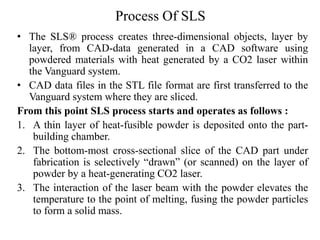
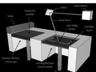
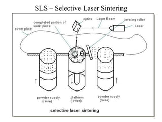
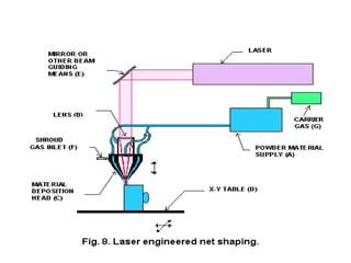
UNIT 4
LASER BASED ADDITIVE
MANUFACTURING SYSTEMS
POWDER BASED SYSTEM
Different types of Powder Based System are :
• Selective Laser Sintering (SLS)
• Three Dimensional Printing (3DP)
• Laser Engineered Net Shaping (LENS)
Powder Based System – Selective Laser Sintering
(SLS)
• 3D Systems Corporation was founded by Charles W. Hull and
Raymond S. Freed in 1986.
• SLS is a additive manufacturing technology for producing models,
prototypes, and patterns.
• There are several models/Products available in SLS
 Sinterstation 2000
 Sinterstation 2500
 Sinterstation 2500 Plus
 Vanguard
The SLS® process is the only technology with the capability
to directly process a variety of engineering thermoplastic materials,
metallic materials, ceramic materials, and thermoplastic composites.
Process Of SLS
• The SLS® process creates three-dimensional objects, layer by
layer, from CAD-data generated in a CAD software using
powdered materials with heat generated by a CO2 laser within
the Vanguard system.
• CAD data files in the STL file format are first transferred to the
Vanguard system where they are sliced.
From this point SLS process starts and operates as follows :
1. A thin layer of heat-fusible powder is deposited onto the part-
building chamber.
2. The bottom-most cross-sectional slice of the CAD part under
fabrication is selectively “drawn” (or scanned) on the layer of
powder by a heat-generating CO2 laser.
3. The interaction of the laser beam with the powder elevates the
temperature to the point of melting, fusing the powder particles
to form a solid mass.
Process Of SLS
4. The intensity of the laser beam is modulated to melt the powder
only in areas defined by the part’s geometry. Surrounding powder
remain a loose compact and serve as supports.
5. When the cross-section is completely drawn, an additional layer of
powder is deposited via a roller mechanism on top of the previously
scanned layer. This prepares the next layer for scanning.
6. Steps 2,3,4 and 5 are repeated, with each layer fusing to the layer
below it. Successive layers of powder are deposited and the process is
repeated until the part is completed.
The SLS® system contains the following hardware components:
(1) Build chamber dimensions (381 × 330 × 457 mm)
(2) Process station (2100 × 1300 × 1900 mm)
(3) Computer cabinet (600 × 600 × 1828 mm)
(4) Chiller (500 × 800 × 900 mm)
SLS – Selective Laser Sintering
Materials Used In SLS
• The Materials used in SLS are:
 Polyamide
 Thermoplastic elastomer
 Polycarbonate
 Nylon
 Metal
Principle Of SLS
• The SLS process is based fundamentally on following principle:
(1) Parts are built by sintering when a CO2 laser beam hits a thin layer of
powdered material.
(2) The interaction of the laser beam with the powder raises the
temperature to the point of melting, resulting in particle bonding,
fusing the particles to themselves and the previous layer to form a
solid.
(3) The building of the part is done layer by layer. Each layer of the
building process contains the cross-sections of one or many parts.
(4) The next layer is then built directly on top of the sintered layer after
an additional layer of powder is deposited via a roller mechanism on
top of the previously formed layer.
Advantages of SLS
(1) Good part stability
(2) Wide range of processing materials
(3) No part supports required
(4) Little post processing required
(5) No post curing required
(6) Advance software support
(1) Large physical size of unit
(2) High power consumption
(3) Poor surface finish
Disadvantages of SLS
Application of SLS
The Vanguard SLS® system can produce a wide range of parts in a
broad variety of applications, including the following
(1) Concept models
(2) Functional models and working prototypes
(3) Polycarbonate (Rapid Casting) patterns
(4) Metal tools (Rapid Tool)
Sinter Bonding
• In the process, particles in each successive layer are fused to each other
and to the previous layer by raising their temperature with the laser beam
to above the glass-transition temperature.
• The glass-transition temperature is the temperature at which the material
begins to soften from a solid to a jelly-like condition.
• This often occurs just prior to the melting temperature at which the
material will be in a molten or liquid state.
• As a result, the particles begin to soften and deform owing to their weight
and cause the surfaces in contact with other particles or solid to deform
and fuse together at these contact surfaces.
• One major advantage of sintering over melting and fusing is that it joins
powder particles into a solid part without going into the liquid phase, thus
avoiding the distortions caused by the flow of molten material during
fusing.
• As the sintering process requires the machine to bring the temperature of
the particles to the glass-transition temperature, the amount of energy
needed is considerable.
• The energy required to sinter bond a similar layer thickness of material is
approx b/w 300 to 500 times higher den photopolymerization.
LASER ENGINEERED NET SHAPING
(LENS)
• Laser engineered net shaping or LENS is a technology developed
by Sandia National Laboratories in 1995 for fabricating metal
parts directly from a computer-aided design (CAD) solid model by
using a metal powder injected into a molten pool created by a
focused, high-powered laser beam.
• Since 1997, Optomec Inc. has focused on commercializing a direct
fabrication process
The system consists of
• A Nd:YAG laser
• A controlled atmosphere glove box,
• A 3- 5axis computer controlled positioning system and
• A powder feed unit.
Process Of LENS
The LENS process build components in an additive manner from
powdered metals using Nd:YAG laser to fuse powder to a solid.
• A deposition head supplies metal powder to the focus of a high
powdered Nd:YAG laser beam to be melted. This laser is
typically directed by fiber optics or precision angled mirrors.
• The laser is focused on a particular spot by a series of lenses,
and a motion system underneath the platform moves
horizontally and laterally as the laser beam traces the cross-
section of the part being produced.
• The fabrication process takes place in a low-pressure argon
chamber for oxygen-free operation in the melting zone,
ensuring that good adhesion is accomplished.
• When a layer is completed, the deposition head moves up and
continues with the next layer. The process is repeated layer by
layer until the part is completed.
• The entire process is usually enclosed to isolate the process
from the atmosphere.
Principle Of LENS
(1) A high powered Nd:YAG laser focused onto a metal substrate
creates a molten puddle on the substrate surface. Powder is then
injected into the molten puddle to increase material volume.
(2) A “printing” motion system moves a platform horizontally and
laterally as the laser beam traces the cross-section of the partbeing
produced. After formation of a layer of the part, the machine’s
powder delivery nozzle moves upwards prior to building next layer.
Advantages of LENS
(1) Superior material properties. The LENS process is capable of
producing fully dense metal parts . Metal parts produced can
also include embedded structures and superior material properties.
The microstructure produced is also relatively good.
(2) Complex parts. Functional metal parts with complex features
are the forte of the LENS system.
(3) Reduced post-processing requirements. Post-processing is
minimized, thus reducing cycle time.
Disadvantages of LENS
(1) Limited materials. The process is currently narrowly focused to
produce only metal parts.
(2) Large physical unit size. The unit requires a relatively large area to
house.
(3) High power consumption. The laser system requires very high
wattage.
APPLICATION OF LENS
LENS can be used in following general application:
(1) Build mold and die inserts
(2) Producing titanium parts in racing industry
(3) Fabricate titanium components for biological implants
(4) Produce functionally gradient structures
THREE-DIMENSIONAL
PRINTING (3DP)
• Z Corporation was incorporated in 1994 by Hatsopoulos, Walter
Bornhost, Tim Anderson and Jim Brett.
• It commercialized its first 3DPrinter, the Z402 System, based on
three-dimensional technology (3DP) in 1997.
• Z Corporation’s latest products are the Z400, Z406 and Z810
systems.
Process Of 3DP
• The machine spreads a layer of powder from the feed box to
cover the surface of the build piston.
• The printer then prints binder solution onto the loose powder,
forming the first cross-section.
• For monochrome parts, Z406 color printer uses all four print
heads to print a single-colored binder.
• For multi-colored parts, each of the four print heads deposits a
different color binder, mixing the four color binders to produce a
spectrum of colors that can be applied to different regions of a
part.
• The powder is glued together at where the binder is printed. The
remaining powder remains loose and supports the layers that
Will be printed above.
• When the cross-section is completed, the build piston is
lowered, a new layer of powder is spread over its surface, and
the process is repeated.
• The part grows layer by layer in the build piston until the part
is completed, completely surrounded and covered by loose
powder.
• Finally the build piston is raised and the loose powder is
vacuumed, revealing the complete part.
• Once a build is completed, the excess powder is vacuumed
and the parts are lifted from the bed.
• Once removed, parts can be finished in a variety of ways to
suit your needs.
Advantages of 3DP
• High speed - Fastest 3D printer to date. Each layer is
printed in seconds, reducing the prototyping time of a
hand-held part to 1 to 2 hours.
• Simple to operate - The office compatible Zcorp system
is straightforward to operate and does not require a
designated technician to build a part.
• No wastage of materials - Powder that is not printed
during the cycle can be reused.
• Color - Enables complex color schemes in RP-ed parts
from a full 24-bit palette of colors.
• Versatile
Disadvantages of 3DP
• Poor surface finish - Parts built by 3D printing have a
relatively poorer surface finish and post-processing is
frequently required.
• Limited functional parts - Relative to the SLS, parts
built are much weaker, thereby limiting the functional
testing capabilities.
• Limited Materials

3D PRINTING- POWDER BASED ADDITIVE MANUFACTURING

  • 1.
    UNIT 4 LASER BASEDADDITIVE MANUFACTURING SYSTEMS
  • 2.
    POWDER BASED SYSTEM Differenttypes of Powder Based System are : • Selective Laser Sintering (SLS) • Three Dimensional Printing (3DP) • Laser Engineered Net Shaping (LENS)
  • 3.
    Powder Based System– Selective Laser Sintering (SLS) • 3D Systems Corporation was founded by Charles W. Hull and Raymond S. Freed in 1986. • SLS is a additive manufacturing technology for producing models, prototypes, and patterns. • There are several models/Products available in SLS  Sinterstation 2000  Sinterstation 2500  Sinterstation 2500 Plus  Vanguard The SLS® process is the only technology with the capability to directly process a variety of engineering thermoplastic materials, metallic materials, ceramic materials, and thermoplastic composites.
  • 4.
    Process Of SLS •The SLS® process creates three-dimensional objects, layer by layer, from CAD-data generated in a CAD software using powdered materials with heat generated by a CO2 laser within the Vanguard system. • CAD data files in the STL file format are first transferred to the Vanguard system where they are sliced. From this point SLS process starts and operates as follows : 1. A thin layer of heat-fusible powder is deposited onto the part- building chamber. 2. The bottom-most cross-sectional slice of the CAD part under fabrication is selectively “drawn” (or scanned) on the layer of powder by a heat-generating CO2 laser. 3. The interaction of the laser beam with the powder elevates the temperature to the point of melting, fusing the powder particles to form a solid mass.
  • 5.
    Process Of SLS 4.The intensity of the laser beam is modulated to melt the powder only in areas defined by the part’s geometry. Surrounding powder remain a loose compact and serve as supports. 5. When the cross-section is completely drawn, an additional layer of powder is deposited via a roller mechanism on top of the previously scanned layer. This prepares the next layer for scanning. 6. Steps 2,3,4 and 5 are repeated, with each layer fusing to the layer below it. Successive layers of powder are deposited and the process is repeated until the part is completed. The SLS® system contains the following hardware components: (1) Build chamber dimensions (381 × 330 × 457 mm) (2) Process station (2100 × 1300 × 1900 mm) (3) Computer cabinet (600 × 600 × 1828 mm) (4) Chiller (500 × 800 × 900 mm)
  • 7.
    SLS – SelectiveLaser Sintering
  • 8.
    Materials Used InSLS • The Materials used in SLS are:  Polyamide  Thermoplastic elastomer  Polycarbonate  Nylon  Metal
  • 9.
    Principle Of SLS •The SLS process is based fundamentally on following principle: (1) Parts are built by sintering when a CO2 laser beam hits a thin layer of powdered material. (2) The interaction of the laser beam with the powder raises the temperature to the point of melting, resulting in particle bonding, fusing the particles to themselves and the previous layer to form a solid. (3) The building of the part is done layer by layer. Each layer of the building process contains the cross-sections of one or many parts. (4) The next layer is then built directly on top of the sintered layer after an additional layer of powder is deposited via a roller mechanism on top of the previously formed layer.
  • 10.
    Advantages of SLS (1)Good part stability (2) Wide range of processing materials (3) No part supports required (4) Little post processing required (5) No post curing required (6) Advance software support (1) Large physical size of unit (2) High power consumption (3) Poor surface finish Disadvantages of SLS
  • 11.
    Application of SLS TheVanguard SLS® system can produce a wide range of parts in a broad variety of applications, including the following (1) Concept models (2) Functional models and working prototypes (3) Polycarbonate (Rapid Casting) patterns (4) Metal tools (Rapid Tool)
  • 12.
    Sinter Bonding • Inthe process, particles in each successive layer are fused to each other and to the previous layer by raising their temperature with the laser beam to above the glass-transition temperature. • The glass-transition temperature is the temperature at which the material begins to soften from a solid to a jelly-like condition. • This often occurs just prior to the melting temperature at which the material will be in a molten or liquid state. • As a result, the particles begin to soften and deform owing to their weight and cause the surfaces in contact with other particles or solid to deform and fuse together at these contact surfaces. • One major advantage of sintering over melting and fusing is that it joins powder particles into a solid part without going into the liquid phase, thus avoiding the distortions caused by the flow of molten material during fusing. • As the sintering process requires the machine to bring the temperature of the particles to the glass-transition temperature, the amount of energy needed is considerable. • The energy required to sinter bond a similar layer thickness of material is approx b/w 300 to 500 times higher den photopolymerization.
  • 13.
    LASER ENGINEERED NETSHAPING (LENS) • Laser engineered net shaping or LENS is a technology developed by Sandia National Laboratories in 1995 for fabricating metal parts directly from a computer-aided design (CAD) solid model by using a metal powder injected into a molten pool created by a focused, high-powered laser beam. • Since 1997, Optomec Inc. has focused on commercializing a direct fabrication process
  • 14.
    The system consistsof • A Nd:YAG laser • A controlled atmosphere glove box, • A 3- 5axis computer controlled positioning system and • A powder feed unit.
  • 15.
    Process Of LENS TheLENS process build components in an additive manner from powdered metals using Nd:YAG laser to fuse powder to a solid. • A deposition head supplies metal powder to the focus of a high powdered Nd:YAG laser beam to be melted. This laser is typically directed by fiber optics or precision angled mirrors. • The laser is focused on a particular spot by a series of lenses, and a motion system underneath the platform moves horizontally and laterally as the laser beam traces the cross- section of the part being produced. • The fabrication process takes place in a low-pressure argon chamber for oxygen-free operation in the melting zone, ensuring that good adhesion is accomplished. • When a layer is completed, the deposition head moves up and continues with the next layer. The process is repeated layer by layer until the part is completed. • The entire process is usually enclosed to isolate the process from the atmosphere.
  • 17.
    Principle Of LENS (1)A high powered Nd:YAG laser focused onto a metal substrate creates a molten puddle on the substrate surface. Powder is then injected into the molten puddle to increase material volume. (2) A “printing” motion system moves a platform horizontally and laterally as the laser beam traces the cross-section of the partbeing produced. After formation of a layer of the part, the machine’s powder delivery nozzle moves upwards prior to building next layer.
  • 18.
    Advantages of LENS (1)Superior material properties. The LENS process is capable of producing fully dense metal parts . Metal parts produced can also include embedded structures and superior material properties. The microstructure produced is also relatively good. (2) Complex parts. Functional metal parts with complex features are the forte of the LENS system. (3) Reduced post-processing requirements. Post-processing is minimized, thus reducing cycle time.
  • 19.
    Disadvantages of LENS (1)Limited materials. The process is currently narrowly focused to produce only metal parts. (2) Large physical unit size. The unit requires a relatively large area to house. (3) High power consumption. The laser system requires very high wattage.
  • 20.
    APPLICATION OF LENS LENScan be used in following general application: (1) Build mold and die inserts (2) Producing titanium parts in racing industry (3) Fabricate titanium components for biological implants (4) Produce functionally gradient structures
  • 21.
    THREE-DIMENSIONAL PRINTING (3DP) • ZCorporation was incorporated in 1994 by Hatsopoulos, Walter Bornhost, Tim Anderson and Jim Brett. • It commercialized its first 3DPrinter, the Z402 System, based on three-dimensional technology (3DP) in 1997. • Z Corporation’s latest products are the Z400, Z406 and Z810 systems.
  • 22.
    Process Of 3DP •The machine spreads a layer of powder from the feed box to cover the surface of the build piston. • The printer then prints binder solution onto the loose powder, forming the first cross-section. • For monochrome parts, Z406 color printer uses all four print heads to print a single-colored binder. • For multi-colored parts, each of the four print heads deposits a different color binder, mixing the four color binders to produce a spectrum of colors that can be applied to different regions of a part. • The powder is glued together at where the binder is printed. The remaining powder remains loose and supports the layers that Will be printed above. • When the cross-section is completed, the build piston is lowered, a new layer of powder is spread over its surface, and the process is repeated.
  • 23.
    • The partgrows layer by layer in the build piston until the part is completed, completely surrounded and covered by loose powder. • Finally the build piston is raised and the loose powder is vacuumed, revealing the complete part. • Once a build is completed, the excess powder is vacuumed and the parts are lifted from the bed. • Once removed, parts can be finished in a variety of ways to suit your needs.
  • 24.
    Advantages of 3DP •High speed - Fastest 3D printer to date. Each layer is printed in seconds, reducing the prototyping time of a hand-held part to 1 to 2 hours. • Simple to operate - The office compatible Zcorp system is straightforward to operate and does not require a designated technician to build a part. • No wastage of materials - Powder that is not printed during the cycle can be reused. • Color - Enables complex color schemes in RP-ed parts from a full 24-bit palette of colors. • Versatile
  • 25.
    Disadvantages of 3DP •Poor surface finish - Parts built by 3D printing have a relatively poorer surface finish and post-processing is frequently required. • Limited functional parts - Relative to the SLS, parts built are much weaker, thereby limiting the functional testing capabilities. • Limited Materials