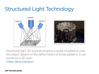
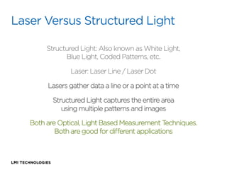
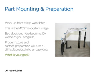
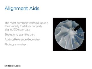
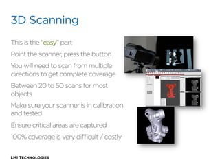
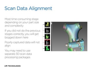
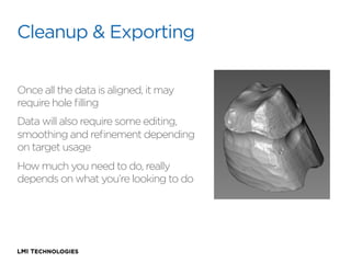
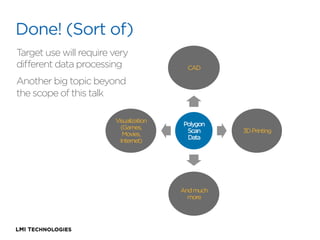
3D Scanning 101
The Fundamentals of the Structured Light
3D Scanning Process
About LMI Technologies
At LMI Technologies, we are passionate about developing
innovative 3D scanning, measurement, and data visualization
technologies that solve complex problems in a simple way. From
concept and design, to manufacturing, we build our products
from the ground up. We take our knowledge and experience
from working in the field and connect our customers to 3D
solutions that enable them to achieve better business results.
Structured Light Technology

Structured light 3D scanner projects a series of patterns onto
the object. Based on the deformation of those patterns, it can
construct a 3D scan.
Video demonstration
Laser Versus Structured Light
Structured Light: Also known as White Light,
Blue Light, Coded Patterns, etc.
Laser: Laser Line / Laser Dot
Lasers gather data a line or a point at a time
Structured Light captures the entire area
using multiple patterns and images
Both are Optical, Light Based Measurement Techniques.
Both are good for different applications
The Assumption

People often perceive that 3D scanning
is a fully automated “magical” process. 
Place the part in front of the 3D scanner,
press a button, and out comes a digital
3D model.
The Reality

Building a complete digital model of an object from all angles is
a process of scanning multiple sides of an object, aligning the
scans, and merging them to create a polygon mesh. From here
the data can be used to do either 3D modeling or measurement
applications.
Restrictions:
•  Highly reflective surfaces
•  Transparent, translucent or emissive
•  Highly occluded surfaces with no line of sight
•  Hard edges and deep concave segments

Great for:
•  Extremely complex surfaces
•  Highly detailed organic surfaces
•  Surfaces that can not be touched
•  Automation with high acquisition speed
•  Anything from 1cm to 3 meters in size
Work Flow
Part Mounting and Part Preparation
Alignment Aids
3D Scanning
Scan Data Alignment
Scan Data Cleanup and Analysis
Export and Use
Part Mounting & Preparation
Work up front = less work later
This is the MOST important stage
Bad decisions here become 10x
worse as you progress
Proper fixture and
surface preparation will turn a
difficult project in to an easy one.
What is your goal?
Alignment Aids
The most common technical issue is
the in-ability to deliver properly
aligned 3D scan data
Strategy to scan the part
Adding Reference Geometry
Photogrammetry
3D Scanning
This is the “easy” part
Point the scanner, press the button
You will need to scan from multiple
directions to get complete coverage
Between 20 to 50 scans for most
objects
Make sure your scanner is in calibration
and tested
Ensure critical areas are captured
100% coverage is very difficult / costly
Scan Data Alignment
Most time consuming stage
depending on your part size
and complexity
If you did not do the previous
stages correctly, you will get
bogged down here
Poorly captured data will not
align
You may need to use
separate 3D scan data
processing packages
Cleanup & Exporting
Once all the data is aligned, it may
require hole filling
Data will also require some editing,
smoothing and refinement depending
on target usage
How much you need to do, really
depends on what you’re looking to do
Done! (Sort of)
Target use will require very
different data processing

CAD

Another big topic beyond
the scope of this talk
Visualization
(Games,
Movies,
Internet)

Polygon
Scan
Data

And much
more

3D Printing
For more information about 3D scanning
or any of LMI Technologies’ products:
Tel: 604 628 6128
Email: learn3D@lmi3d.com
Website: http:/
/www.lmi3d.com
סריקת תלת מימד

סריקת תלת מימד

  • 1.
    3D Scanning 101 TheFundamentals of the Structured Light 3D Scanning Process
  • 2.
    About LMI Technologies AtLMI Technologies, we are passionate about developing innovative 3D scanning, measurement, and data visualization technologies that solve complex problems in a simple way. From concept and design, to manufacturing, we build our products from the ground up. We take our knowledge and experience from working in the field and connect our customers to 3D solutions that enable them to achieve better business results.
  • 3.
    Structured Light Technology Structuredlight 3D scanner projects a series of patterns onto the object. Based on the deformation of those patterns, it can construct a 3D scan. Video demonstration
  • 4.
    Laser Versus StructuredLight Structured Light: Also known as White Light, Blue Light, Coded Patterns, etc. Laser: Laser Line / Laser Dot Lasers gather data a line or a point at a time Structured Light captures the entire area using multiple patterns and images Both are Optical, Light Based Measurement Techniques. Both are good for different applications
  • 5.
    The Assumption People oftenperceive that 3D scanning is a fully automated “magical” process.  Place the part in front of the 3D scanner, press a button, and out comes a digital 3D model.
  • 6.
    The Reality Building acomplete digital model of an object from all angles is a process of scanning multiple sides of an object, aligning the scans, and merging them to create a polygon mesh. From here the data can be used to do either 3D modeling or measurement applications.
  • 7.
    Restrictions: •  Highly reflectivesurfaces •  Transparent, translucent or emissive •  Highly occluded surfaces with no line of sight •  Hard edges and deep concave segments Great for: •  Extremely complex surfaces •  Highly detailed organic surfaces •  Surfaces that can not be touched •  Automation with high acquisition speed •  Anything from 1cm to 3 meters in size
  • 8.
    Work Flow Part Mountingand Part Preparation Alignment Aids 3D Scanning Scan Data Alignment Scan Data Cleanup and Analysis Export and Use
  • 9.
    Part Mounting &Preparation Work up front = less work later This is the MOST important stage Bad decisions here become 10x worse as you progress Proper fixture and surface preparation will turn a difficult project in to an easy one. What is your goal?
  • 10.
    Alignment Aids The mostcommon technical issue is the in-ability to deliver properly aligned 3D scan data Strategy to scan the part Adding Reference Geometry Photogrammetry
  • 11.
    3D Scanning This isthe “easy” part Point the scanner, press the button You will need to scan from multiple directions to get complete coverage Between 20 to 50 scans for most objects Make sure your scanner is in calibration and tested Ensure critical areas are captured 100% coverage is very difficult / costly
  • 12.
    Scan Data Alignment Mosttime consuming stage depending on your part size and complexity If you did not do the previous stages correctly, you will get bogged down here Poorly captured data will not align You may need to use separate 3D scan data processing packages
  • 13.
    Cleanup & Exporting Onceall the data is aligned, it may require hole filling Data will also require some editing, smoothing and refinement depending on target usage How much you need to do, really depends on what you’re looking to do
  • 14.
    Done! (Sort of) Targetuse will require very different data processing CAD Another big topic beyond the scope of this talk Visualization (Games, Movies, Internet) Polygon Scan Data And much more 3D Printing
  • 15.
    For more informationabout 3D scanning or any of LMI Technologies’ products: Tel: 604 628 6128 Email: learn3D@lmi3d.com Website: http:/ /www.lmi3d.com