Downloaded 1,076 times
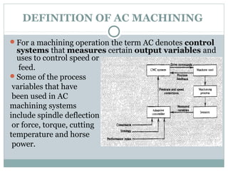
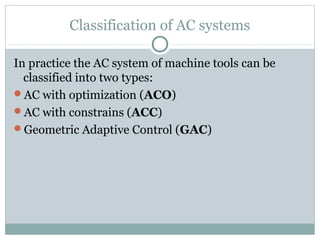
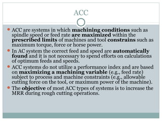
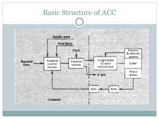


This document discusses adaptive control systems for machining. It defines adaptive control as a feedback system that automatically adjusts machining variables like cutting speed and feed rate based on actual process conditions. The three main functions of adaptive control are identification, decision, and modification. Adaptive control systems are classified as adaptive control with optimization, which uses a performance index, or adaptive control with constraints, which maximizes variables within set limits. Benefits include increased production and tool life, while limitations include lack of reliable tool sensors and standardized interfaces with CNC units.