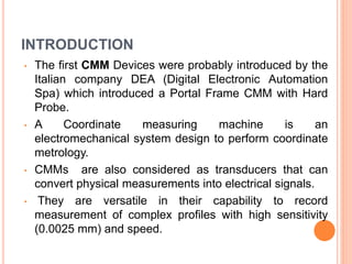
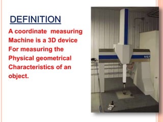
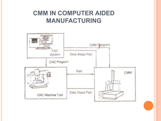
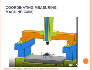
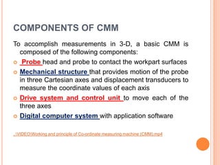
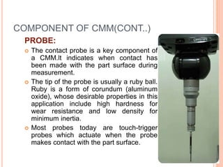
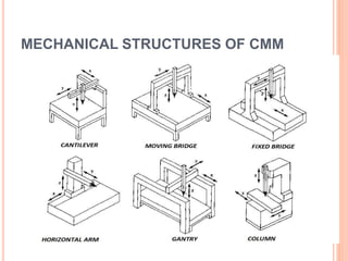
COORDINATE MEASURING
MACHINE(CMM)
INTRODUCTION
• The first CMM Devices were probably introduced by the
Italian company DEA (Digital Electronic Automation
Spa) which introduced a Portal Frame CMM with Hard
Probe.
• A Coordinate measuring machine is an
electromechanical system design to perform coordinate
metrology.
• CMMs are also considered as transducers that can
convert physical measurements into electrical signals.
• They are versatile in their capability to record
measurement of complex profiles with high sensitivity
(0.0025 mm) and speed.
DEFINITION
A coordinate measuring
Machine is a 3D device
For measuring the
Physical geometrical
Characteristics of an
object.
CMM IN COMPUTER AIDED
MANUFACTURING
Description
The typical 3 "bridge" CMM is
composed of three axes, an X, Y and
Z.
These axes are orthogonal to each
other in a typical three dimensional
coordinate system.
Each axis has a scale system that
indicates the location of that axis.
The machine will read the input from
the touch probe, as directed by the
operator or programmer.
The machine then uses the X,Y,Z
coordinates of each of these points to
determine size and position with
micrometer precision typically.
Reference
..VIDEONX CMM Inspection Programming.mp4
COORDINATING MEASURING
MACHINE(CMM)
..VIDEOUNIVERSAL COORDINATE MEASURING MACHINE.mp4
COMPONENTS OF CMM
To accomplish measurements in 3-D, a basic CMM is
composed of the following components:
 Probe head and probe to contact the workpart surfaces
 Mechanical structure that provides motion of the probe
in three Cartesian axes and displacement transducers to
measure the coordinate values of each axis
 Drive system and control unit to move each of the
three axes
 Digital computer system with application software
..VIDEOWorking and principle of Co-ordinate measuring machine (CMM).mp4
COMPONENT OF CMM(CONT..)
PROBE:
 The contact probe is a key component of
a CMM.lt indicates when contact has
been made with the part surface during
measurement.
 The tip of the probe is usually a ruby ball.
Ruby is a form of corundum (aluminum
oxide), whose desirable properties in this
application include high hardness for
wear resistance and low density for
minimum inertia.
 Most probes today are touch-trigger
probes which actuate when the probe
makes contact with the part surface.
TYPES OF CMM
Ass per the mechanical structure the CMM are
classified into
six types , which are as follows:
 CANTILEVER
 MOVING BRIDGE
 FIXED BRIDGE
 HORIZONTAL ARM
 GANTRY
 COLUMN
MECHANICAL STRUCTURES OF CMM
CMM WORKING
 After placing a workpiece on the
machine table, a probe is used to
measure different points on it by
mapping the x, y, z coordinates.
 The probe operates either
manually via an operator or
automatically via a control system.
 These points are then uploaded to
a computer interface where they
can be analyzed using modeling
software (e.g. CAD) and
regression algorithms for further
development.

Coordinate Measuring Machine(CMM)

  • 1.
  • 2.
    INTRODUCTION • The firstCMM Devices were probably introduced by the Italian company DEA (Digital Electronic Automation Spa) which introduced a Portal Frame CMM with Hard Probe. • A Coordinate measuring machine is an electromechanical system design to perform coordinate metrology. • CMMs are also considered as transducers that can convert physical measurements into electrical signals. • They are versatile in their capability to record measurement of complex profiles with high sensitivity (0.0025 mm) and speed.
  • 3.
    DEFINITION A coordinate measuring Machineis a 3D device For measuring the Physical geometrical Characteristics of an object.
  • 4.
    CMM IN COMPUTERAIDED MANUFACTURING
  • 5.
    Description The typical 3"bridge" CMM is composed of three axes, an X, Y and Z. These axes are orthogonal to each other in a typical three dimensional coordinate system. Each axis has a scale system that indicates the location of that axis. The machine will read the input from the touch probe, as directed by the operator or programmer. The machine then uses the X,Y,Z coordinates of each of these points to determine size and position with micrometer precision typically. Reference ..VIDEONX CMM Inspection Programming.mp4
  • 6.
  • 7.
    COMPONENTS OF CMM Toaccomplish measurements in 3-D, a basic CMM is composed of the following components:  Probe head and probe to contact the workpart surfaces  Mechanical structure that provides motion of the probe in three Cartesian axes and displacement transducers to measure the coordinate values of each axis  Drive system and control unit to move each of the three axes  Digital computer system with application software ..VIDEOWorking and principle of Co-ordinate measuring machine (CMM).mp4
  • 8.
    COMPONENT OF CMM(CONT..) PROBE: The contact probe is a key component of a CMM.lt indicates when contact has been made with the part surface during measurement.  The tip of the probe is usually a ruby ball. Ruby is a form of corundum (aluminum oxide), whose desirable properties in this application include high hardness for wear resistance and low density for minimum inertia.  Most probes today are touch-trigger probes which actuate when the probe makes contact with the part surface.
  • 9.
    TYPES OF CMM Assper the mechanical structure the CMM are classified into six types , which are as follows:  CANTILEVER  MOVING BRIDGE  FIXED BRIDGE  HORIZONTAL ARM  GANTRY  COLUMN
  • 10.
  • 11.
    CMM WORKING  Afterplacing a workpiece on the machine table, a probe is used to measure different points on it by mapping the x, y, z coordinates.  The probe operates either manually via an operator or automatically via a control system.  These points are then uploaded to a computer interface where they can be analyzed using modeling software (e.g. CAD) and regression algorithms for further development.

Editor's Notes

  • #2 PRESENTED BY: NIKHIL BHAGAT (13MT07IND006)