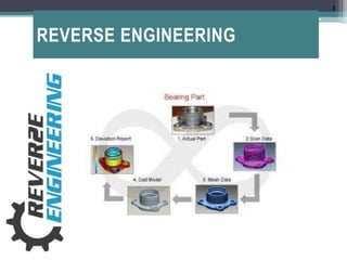
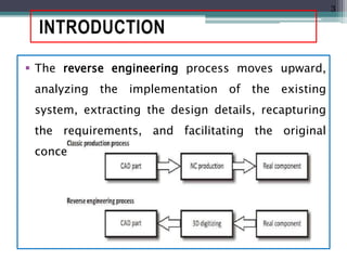
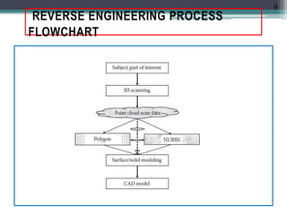
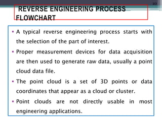
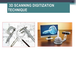
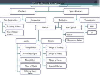
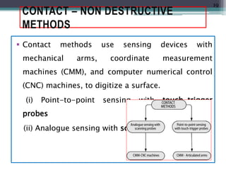
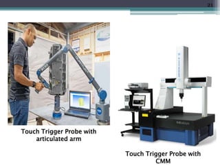
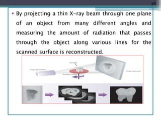
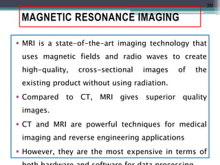
REVERSE ENGINEERING
1
INTRODUCTION
 Engineering is the process of designing,
manufacturing, assembling, and maintaining
products and systems.
• Forward Engineering
• Reverse Engineering
 Forward engineering is the traditional process of
moving from high-level abstractions and logical
designs to the physical implementation of a
system.
2
INTRODUCTION
 The reverse engineering process moves upward,
analyzing the implementation of the existing
system, extracting the design details, recapturing
the requirements, and facilitating the original
concept.
3
REVERSE ENGINEERING
 Reverse engineering is the process of duplicating an
existing part, sub-assembly, or product, without
drawings, documentation, or a computer model.
 The Society of Manufacturing Engineers (SME) states
as “starting with a finished product or process and
working backward in logical fashion to discover the
underlying new technology”
This chapter will define the concept of reverse
engineering systems that are typically utilized in
design and rapid prototyping manufacturing
4
REASON FOR REVERSE
ENGINEERING
Examples: 1
 In some situations, designers give a shape to their
ideas by using clay, plaster, wood, or foam rubber.
CAD model
 As products become more organic in shape,
designing in CAD may be challenging or
impossible.
 There is no guarantee that the CAD model will be
acceptably close to the sculpted model.
5
REASON FOR REVERSE
ENGINEERING
Examples: 2
 When a new car is launched on the market,
competing manufacturers want to know about how
it works.
CAD model
 Competing manufacturers may buy one product
and disassemble it to learn how it was built and
how it works.
Solution
6
USE OF REVERSE ENGINEERING
 There is inadequate documentation of the original
design.
 The original product design documentation has
been lost or never existed.
 Analyzing the good and bad features of
competitors’ products.
 The original supplier is unable or unwilling to
provide additional parts.
 The original manufacturer of a product no longer
7
USE OF REVERSE ENGINEERING
 To compress product development cycle times. By
using reverse engineering, a three-dimensional
physical product can be quickly captured in the
digital form, remodeled, and exported.
 Creating data to restore of manufacture a part for
which there are no CAD data.
 Exploring new possibility to improve product
performance and features.
8
REVERSE ENGINEERING PROCESS
FLOWCHART
9
REVERSE ENGINEERING PROCESS
FLOWCHART
 A typical reverse engineering process starts with
the selection of the part of interest.
 Proper measurement devices for data acquisition
are then used to generate raw data, usually a point
cloud data file.
 The point cloud is a set of 3D points or data
coordinates that appear as a cloud or cluster.
 Point clouds are not directly usable in most
engineering applications.
10
REVERSE ENGINEERING PROCESS
FLOWCHART
 Point clouds are converted to a proper format, such
as a polygon mesh, nonuniform rational B-spline
(NURBS) surface models, or computer-aided design
(CAD) models.
 Point clouds data is used as input for design,
modeling, and measuring through a process
referred to as reverse engineering.
11
REVERSE ENGINEERING PROCESS
FLOWCHART
12
(a) Wireframe polygonal model (b) Polygonal surface model
(c) NURBS model
REVERSE ENGINEERING PROCESS
FLOWCHART
 The primary technologies to transform a point
cloud data set obtained by scanning into a CAD
modeling are based on the formation of triangular
polyhedral mesh.
 Increasing the number of triangles will yield a
better presentation of the surface, but will increase
the file size at the same time.
 The software file for triangulation is usually written
in the Standard Triangulation Language (STL),
frequently referred to as STL format.
13
3D SCANNING DIGITIZATION
TECHNIQUE
14
3D SCANNING DIGITIZATION TECHNIQUE
 The technology to capture 3D data of objects has
been remarkable improved in recent years.
 Advanced software and increasingly powerful
computers allow a large database and fast data
post-processing.
 3D scanners play an important role in vision-based
3D scanning technology.
1. Contact Techniques.
2. Non-Contact Techniques.
15
CONTACT DATA TECHNIQUE
 Contact data acquisition obtains data using a
contact measuring process.
 Contact means that the measuring probe touches
the recovery surface of objects during the data
acquisition.
 The devices include joined arms and CMMs.
Destructive and non-destructive methods are used
in contact measuring process
16
NON-CONTACT DATA TECHNIQUE
 Non-Contact data acquisition technology uses an
energy source, such as laser, white light,
microwave, radar, and ultrasonic sound, to obtain
3D data of an object without touching the surface
of objects in the measurement.
 There are two techniques used to receive signals of
the energy source from measured surface:
 Reflective methods
 Transmissive methods
17
3D Digitization Technology3D Digitization Technology
Contact Non - Contact
Non-Destructive Destructive
MRIScanning probes
Touch Trigger
probes
Reflective Transmissive
CT
Optical Non-Optical
Sonar
Microwave RadarActive Passive
Triangulation
Structured Light
Moire Effect
Time of Flight
Coherent Laser
Radar
Shape of Shading
Shape of Stereo
Shape of Focus
Shape of Motion
18
CONTACT – NON DESTRUCTIVE
METHODS
 Contact methods use sensing devices with
mechanical arms, coordinate measurement
machines (CMM), and computer numerical control
(CNC) machines, to digitize a surface.
(i) Point-to-point sensing with touch-trigger
probes
(ii) Analogue sensing with scanning probes
19
TOUCH TRIGGER PROBES
 In this technique, a touch-trigger probe is used
that is installed on a CMM or on an articulated
mechanical arm to gather the coordinate points of
a surface.
 A CMM with a touch-trigger probe can be
programmed to follow planned paths along a
surface. A CMM provides more accurate
measurement data compared to the articulated
arm.
20
Touch Trigger Probe with
articulated arm
Touch Trigger Probe with
CMM
21
SCANNING PROBES
 In analogue sensing, a scanning probe is used that
is installed on a CMM or CNC machine.
 When scanning, the probe stylus tip contacts the
feature and then moves continuously along the
surface, gathering data as it moves.
 The scanning speed in analogue sensing is up to
three times faster than in point-to-point sensing.
22
A milling machine with scanning probe
23
CONTACT – DESTRUCTIVE METHODS
 This destructive method is useful for reverse
engineering small and complex objects in which
both internal and external features are scanned.
 A CNC milling machine exposes images, which are
then gathered by a CCD (charge coupled device)
camera.
 The scanning software automatically converts the
digital bitmap image to edge detected points, as
the part is scanned.
24
CONTACT – DESTRUCTIVE METHODS
 In RP processes, the part is built layer-by-layer based
on 2-D slice data.
 The destructive RE process is the reverse of this. To
remodel the part, 2-D slice images of the part are
gathered by destroying the part layer-by-layer.
 The disadvantage of this method is the destruction of
the object even though the technique is fast and
accurate.
 It can work with any machinable object like aluminum
alloys, plastics, steel, cast iron, stainless steel,
25
CONTACT – ADVANTAGES &
DISADVANTAGES
Advantages:
 High accuracy.
 Low costs.
 Ability to measure deep slots and pockets.
 Insensitivity to color or transparency.
Disadvantages:
 Slow data collection.
 Distortion of soft objects by the probe.
26
NON-CONTACT – ACTIVE METHODS
 In noncontact methods, 2-D cross-sectional images
of objects are captured by projecting energy sources
(light, sound, or magnetic fields) onto an object, then
either the transmitted or the reflected energy is
observed.
 The geometric data for an object are finally calculated
by using triangulation, time-of-flight, wave-
interference information, and image processing
algorithms.
 There is no contact between the RE hardware and an
27
TRIANGULATION
 Triangulation is a method that employs position and
angles between light sources and photosensitive
devices (CCD–charge-coupled device camera) to
calculate coordinates.
 A device transmits a light spot on the object at a
defined angle. A CCD camera detects the position of
the reflected point on the surface.
 We can use two variants of triangulation schemes
using CCD cameras: single and double CCD camera.
28
29
STRUCTURED-LIGHT SYSTEMS
 Structured-light systems have the following strong
advantages compared to laser systems;
 Data acquisition is very fast (up to millions of points per
second).
 Color texture information is available.
 Used in digitizing images of human beings.
30
INTERFEROMETRY (MOIRÉ EFFECTS)
 The interferometry technique is well known in
dimensional inspection as well as in flatness and
deformation measurements.
 The structured-light patterns are projected onto a
surface to produce shadow Moiré effects.
 Moiré effects are captured in an image and analyzed
to determine distances between the lines.
 This distance is proportional to the height of the
surface at the point of interest, and so the surface
coordinates can be calculated.
31
INTERFEROMETRY (MOIRÉ EFFECTS)
 The figure shows the formation of moiré fringes by
superimposing a line pattern with concentric circles
and two other line patterns that vary in line spacing
and rotation.
32
TIME OF FLIGHT
 The principle behind TOF is to measure the amount
of time (t) that a light pulse (i.e., laser
electromagnetic radiation) takes to travel to the
object and return.
 Because the speed of light (C) is known, it is possible
to determine the distance traveled.
 The distance (D) of the object from the laser would
then be equal to approximately one half of the
distance the laser pulse traveled.
D = C × t/2
33
TIME OF FLIGHT
 The main disadvantage is that TOF scanners are large
and do not capture an object’s texture, only its
geometry.
34
NON-CONTACT– PASSIVE METHODS
 Passive methods reconstruct a 3-D model of an
object by analyzing the images to determine
coordinate data.
 It is similar to active methods in its use of imaging
frames for 3-D reconstruction.
 However in passive methods, there is no projection
of light sources onto the object for data
acquisition.
 There are many different passive methods, such as
35
NON-CONTACT– PASSIVE METHODS
 The typical passive methods are shape from
shading and shape from stereo.
 Shapes from shading (SFS) methods are used to
reconstruct a 3-D representation of an object from
a single image (2-D input) based on shading
information.
Drawbacks:
 The shadow areas of an object cannot be recovered
reliably because they do not provide enough intensity
information.
36
NON-CONTACT METHODS –
TRANSMISSIVE
Computerized tomography
 CT is a powerful transmissive approach for 3-D
reconstruction.
 It has also been called as computerized axial
tomography (CAT) or computerized transaxial
tomography (CTAT) or digital axial tomography
(DAT).
 CT is a nondestructive method that allows three-
dimensional visualization of the internals of an
37
 By projecting a thin X-ray beam through one plane
of an object from many different angles and
measuring the amount of radiation that passes
through the object along various lines for the
scanned surface is reconstructed.
38
MAGNETIC RESONANCE IMAGING
 MRI is a state-of-the-art imaging technology that
uses magnetic fields and radio waves to create
high-quality, cross-sectional images of the
existing product without using radiation.
 Compared to CT, MRI gives superior quality
images.
 CT and MRI are powerful techniques for medical
imaging and reverse engineering applications
 However, they are the most expensive in terms of
39
ADVANTAGES & DISADVANTAGES
Advantages:
 No physical contact.
 Ability to detect colors.
 Ability to scan highly detailed objects, where
mechanical touch probes may be too large to
accomplish the task.
 Fast digitizing of substantial volumes.
Disadvantages:
 Possible limitations for colored, transparent, or
reflective surfaces.
40
SURFACE AND SOLID MODEL
RECONSTRUCTION
 One of the first steps in reverse engineering is to
reconstruct the subject of interest from the data
obtained by scanners or probes.
 The process can be divided into four phases:
 Data acquisition
 Polygonization
 Refinement
 Model generation
41
SURFACE AND SOLID MODEL
RECONSTRUCTION
 New data acquisition is accomplished with various
measurement instruments, such as a three-
dimensional (3D) scanner or a direct-contact
probe.
 The accuracy of the data largely depends on the
reliability and precision of these instruments.
 The Polygonization process is completed using the
software installed with these instruments.
42
SURFACE AND SOLID MODEL
RECONSTRUCTION
 Polygonization process is often followed up with a
refinement phase such as segmentation to separate
and group data point sets.
 Related mathematical techniques include automatic
surface fitting and constrained fitting are also used
for computer model refinement.
 The details and quality of the final surface models
depend on the data collected, the mathematical
methods utilized, and the intended application.
43

3D PRINTING - REVERSE ENGINEERING

  • 1.
  • 2.
    INTRODUCTION  Engineering isthe process of designing, manufacturing, assembling, and maintaining products and systems. • Forward Engineering • Reverse Engineering  Forward engineering is the traditional process of moving from high-level abstractions and logical designs to the physical implementation of a system. 2
  • 3.
    INTRODUCTION  The reverseengineering process moves upward, analyzing the implementation of the existing system, extracting the design details, recapturing the requirements, and facilitating the original concept. 3
  • 4.
    REVERSE ENGINEERING  Reverseengineering is the process of duplicating an existing part, sub-assembly, or product, without drawings, documentation, or a computer model.  The Society of Manufacturing Engineers (SME) states as “starting with a finished product or process and working backward in logical fashion to discover the underlying new technology” This chapter will define the concept of reverse engineering systems that are typically utilized in design and rapid prototyping manufacturing 4
  • 5.
    REASON FOR REVERSE ENGINEERING Examples:1  In some situations, designers give a shape to their ideas by using clay, plaster, wood, or foam rubber. CAD model  As products become more organic in shape, designing in CAD may be challenging or impossible.  There is no guarantee that the CAD model will be acceptably close to the sculpted model. 5
  • 6.
    REASON FOR REVERSE ENGINEERING Examples:2  When a new car is launched on the market, competing manufacturers want to know about how it works. CAD model  Competing manufacturers may buy one product and disassemble it to learn how it was built and how it works. Solution 6
  • 7.
    USE OF REVERSEENGINEERING  There is inadequate documentation of the original design.  The original product design documentation has been lost or never existed.  Analyzing the good and bad features of competitors’ products.  The original supplier is unable or unwilling to provide additional parts.  The original manufacturer of a product no longer 7
  • 8.
    USE OF REVERSEENGINEERING  To compress product development cycle times. By using reverse engineering, a three-dimensional physical product can be quickly captured in the digital form, remodeled, and exported.  Creating data to restore of manufacture a part for which there are no CAD data.  Exploring new possibility to improve product performance and features. 8
  • 9.
  • 10.
    REVERSE ENGINEERING PROCESS FLOWCHART A typical reverse engineering process starts with the selection of the part of interest.  Proper measurement devices for data acquisition are then used to generate raw data, usually a point cloud data file.  The point cloud is a set of 3D points or data coordinates that appear as a cloud or cluster.  Point clouds are not directly usable in most engineering applications. 10
  • 11.
    REVERSE ENGINEERING PROCESS FLOWCHART Point clouds are converted to a proper format, such as a polygon mesh, nonuniform rational B-spline (NURBS) surface models, or computer-aided design (CAD) models.  Point clouds data is used as input for design, modeling, and measuring through a process referred to as reverse engineering. 11
  • 12.
    REVERSE ENGINEERING PROCESS FLOWCHART 12 (a)Wireframe polygonal model (b) Polygonal surface model (c) NURBS model
  • 13.
    REVERSE ENGINEERING PROCESS FLOWCHART The primary technologies to transform a point cloud data set obtained by scanning into a CAD modeling are based on the formation of triangular polyhedral mesh.  Increasing the number of triangles will yield a better presentation of the surface, but will increase the file size at the same time.  The software file for triangulation is usually written in the Standard Triangulation Language (STL), frequently referred to as STL format. 13
  • 14.
  • 15.
    3D SCANNING DIGITIZATIONTECHNIQUE  The technology to capture 3D data of objects has been remarkable improved in recent years.  Advanced software and increasingly powerful computers allow a large database and fast data post-processing.  3D scanners play an important role in vision-based 3D scanning technology. 1. Contact Techniques. 2. Non-Contact Techniques. 15
  • 16.
    CONTACT DATA TECHNIQUE Contact data acquisition obtains data using a contact measuring process.  Contact means that the measuring probe touches the recovery surface of objects during the data acquisition.  The devices include joined arms and CMMs. Destructive and non-destructive methods are used in contact measuring process 16
  • 17.
    NON-CONTACT DATA TECHNIQUE Non-Contact data acquisition technology uses an energy source, such as laser, white light, microwave, radar, and ultrasonic sound, to obtain 3D data of an object without touching the surface of objects in the measurement.  There are two techniques used to receive signals of the energy source from measured surface:  Reflective methods  Transmissive methods 17
  • 18.
    3D Digitization Technology3DDigitization Technology Contact Non - Contact Non-Destructive Destructive MRIScanning probes Touch Trigger probes Reflective Transmissive CT Optical Non-Optical Sonar Microwave RadarActive Passive Triangulation Structured Light Moire Effect Time of Flight Coherent Laser Radar Shape of Shading Shape of Stereo Shape of Focus Shape of Motion 18
  • 19.
    CONTACT – NONDESTRUCTIVE METHODS  Contact methods use sensing devices with mechanical arms, coordinate measurement machines (CMM), and computer numerical control (CNC) machines, to digitize a surface. (i) Point-to-point sensing with touch-trigger probes (ii) Analogue sensing with scanning probes 19
  • 20.
    TOUCH TRIGGER PROBES In this technique, a touch-trigger probe is used that is installed on a CMM or on an articulated mechanical arm to gather the coordinate points of a surface.  A CMM with a touch-trigger probe can be programmed to follow planned paths along a surface. A CMM provides more accurate measurement data compared to the articulated arm. 20
  • 21.
    Touch Trigger Probewith articulated arm Touch Trigger Probe with CMM 21
  • 22.
    SCANNING PROBES  Inanalogue sensing, a scanning probe is used that is installed on a CMM or CNC machine.  When scanning, the probe stylus tip contacts the feature and then moves continuously along the surface, gathering data as it moves.  The scanning speed in analogue sensing is up to three times faster than in point-to-point sensing. 22
  • 23.
    A milling machinewith scanning probe 23
  • 24.
    CONTACT – DESTRUCTIVEMETHODS  This destructive method is useful for reverse engineering small and complex objects in which both internal and external features are scanned.  A CNC milling machine exposes images, which are then gathered by a CCD (charge coupled device) camera.  The scanning software automatically converts the digital bitmap image to edge detected points, as the part is scanned. 24
  • 25.
    CONTACT – DESTRUCTIVEMETHODS  In RP processes, the part is built layer-by-layer based on 2-D slice data.  The destructive RE process is the reverse of this. To remodel the part, 2-D slice images of the part are gathered by destroying the part layer-by-layer.  The disadvantage of this method is the destruction of the object even though the technique is fast and accurate.  It can work with any machinable object like aluminum alloys, plastics, steel, cast iron, stainless steel, 25
  • 26.
    CONTACT – ADVANTAGES& DISADVANTAGES Advantages:  High accuracy.  Low costs.  Ability to measure deep slots and pockets.  Insensitivity to color or transparency. Disadvantages:  Slow data collection.  Distortion of soft objects by the probe. 26
  • 27.
    NON-CONTACT – ACTIVEMETHODS  In noncontact methods, 2-D cross-sectional images of objects are captured by projecting energy sources (light, sound, or magnetic fields) onto an object, then either the transmitted or the reflected energy is observed.  The geometric data for an object are finally calculated by using triangulation, time-of-flight, wave- interference information, and image processing algorithms.  There is no contact between the RE hardware and an 27
  • 28.
    TRIANGULATION  Triangulation isa method that employs position and angles between light sources and photosensitive devices (CCD–charge-coupled device camera) to calculate coordinates.  A device transmits a light spot on the object at a defined angle. A CCD camera detects the position of the reflected point on the surface.  We can use two variants of triangulation schemes using CCD cameras: single and double CCD camera. 28
  • 29.
  • 30.
    STRUCTURED-LIGHT SYSTEMS  Structured-lightsystems have the following strong advantages compared to laser systems;  Data acquisition is very fast (up to millions of points per second).  Color texture information is available.  Used in digitizing images of human beings. 30
  • 31.
    INTERFEROMETRY (MOIRÉ EFFECTS) The interferometry technique is well known in dimensional inspection as well as in flatness and deformation measurements.  The structured-light patterns are projected onto a surface to produce shadow Moiré effects.  Moiré effects are captured in an image and analyzed to determine distances between the lines.  This distance is proportional to the height of the surface at the point of interest, and so the surface coordinates can be calculated. 31
  • 32.
    INTERFEROMETRY (MOIRÉ EFFECTS) The figure shows the formation of moiré fringes by superimposing a line pattern with concentric circles and two other line patterns that vary in line spacing and rotation. 32
  • 33.
    TIME OF FLIGHT The principle behind TOF is to measure the amount of time (t) that a light pulse (i.e., laser electromagnetic radiation) takes to travel to the object and return.  Because the speed of light (C) is known, it is possible to determine the distance traveled.  The distance (D) of the object from the laser would then be equal to approximately one half of the distance the laser pulse traveled. D = C × t/2 33
  • 34.
    TIME OF FLIGHT The main disadvantage is that TOF scanners are large and do not capture an object’s texture, only its geometry. 34
  • 35.
    NON-CONTACT– PASSIVE METHODS Passive methods reconstruct a 3-D model of an object by analyzing the images to determine coordinate data.  It is similar to active methods in its use of imaging frames for 3-D reconstruction.  However in passive methods, there is no projection of light sources onto the object for data acquisition.  There are many different passive methods, such as 35
  • 36.
    NON-CONTACT– PASSIVE METHODS The typical passive methods are shape from shading and shape from stereo.  Shapes from shading (SFS) methods are used to reconstruct a 3-D representation of an object from a single image (2-D input) based on shading information. Drawbacks:  The shadow areas of an object cannot be recovered reliably because they do not provide enough intensity information. 36
  • 37.
    NON-CONTACT METHODS – TRANSMISSIVE Computerizedtomography  CT is a powerful transmissive approach for 3-D reconstruction.  It has also been called as computerized axial tomography (CAT) or computerized transaxial tomography (CTAT) or digital axial tomography (DAT).  CT is a nondestructive method that allows three- dimensional visualization of the internals of an 37
  • 38.
     By projectinga thin X-ray beam through one plane of an object from many different angles and measuring the amount of radiation that passes through the object along various lines for the scanned surface is reconstructed. 38
  • 39.
    MAGNETIC RESONANCE IMAGING MRI is a state-of-the-art imaging technology that uses magnetic fields and radio waves to create high-quality, cross-sectional images of the existing product without using radiation.  Compared to CT, MRI gives superior quality images.  CT and MRI are powerful techniques for medical imaging and reverse engineering applications  However, they are the most expensive in terms of 39
  • 40.
    ADVANTAGES & DISADVANTAGES Advantages: No physical contact.  Ability to detect colors.  Ability to scan highly detailed objects, where mechanical touch probes may be too large to accomplish the task.  Fast digitizing of substantial volumes. Disadvantages:  Possible limitations for colored, transparent, or reflective surfaces. 40
  • 41.
    SURFACE AND SOLIDMODEL RECONSTRUCTION  One of the first steps in reverse engineering is to reconstruct the subject of interest from the data obtained by scanners or probes.  The process can be divided into four phases:  Data acquisition  Polygonization  Refinement  Model generation 41
  • 42.
    SURFACE AND SOLIDMODEL RECONSTRUCTION  New data acquisition is accomplished with various measurement instruments, such as a three- dimensional (3D) scanner or a direct-contact probe.  The accuracy of the data largely depends on the reliability and precision of these instruments.  The Polygonization process is completed using the software installed with these instruments. 42
  • 43.
    SURFACE AND SOLIDMODEL RECONSTRUCTION  Polygonization process is often followed up with a refinement phase such as segmentation to separate and group data point sets.  Related mathematical techniques include automatic surface fitting and constrained fitting are also used for computer model refinement.  The details and quality of the final surface models depend on the data collected, the mathematical methods utilized, and the intended application. 43