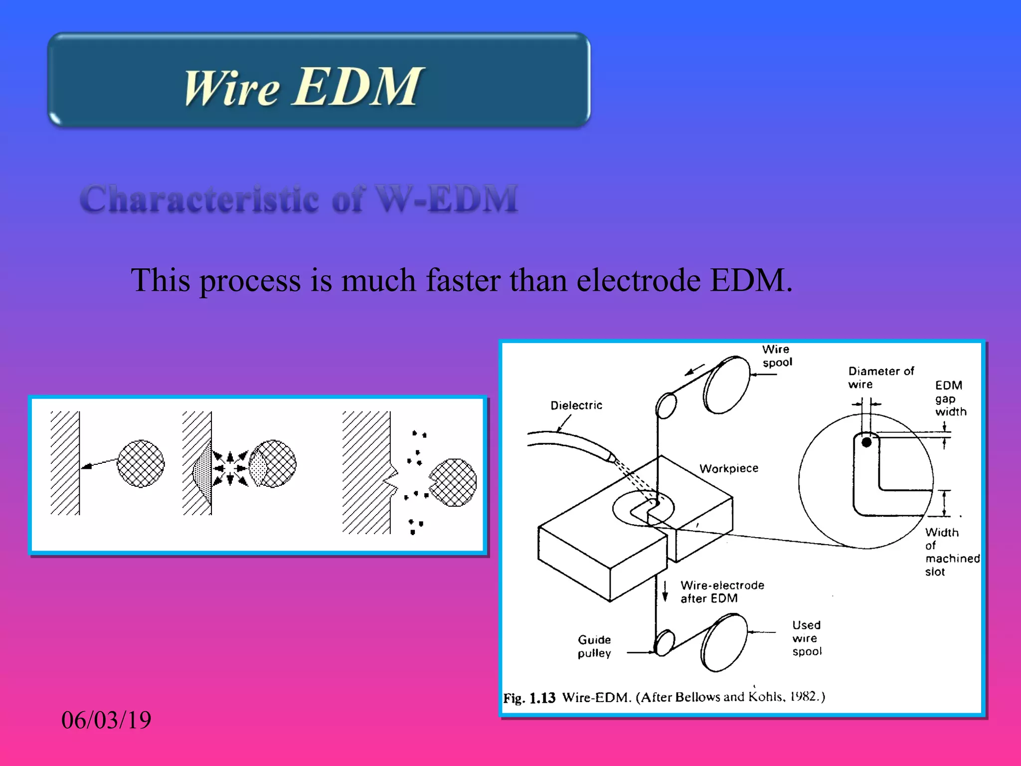
Section : EDMⅢSection : EDMⅢ
 The tool (electrode) usually acts as a cathode and is
immersed in a dielectric fluid.
 DC voltage (~300V) is applied in modulated pulses
(200-500K Hz).
 The dielectric breaks down (sparking at around
12,000 deg F) when gap is small.
 The sparks erodes the work piece in the shape of the tool.
 The tool is progressively lowered as the work piece erodes.
 Material removal rate is typically 300 mm3
/min
 Tool wear ratio 3:1 with metallic electrodes, 3:1-100:1
with graphite electrodes
• Pulsed power supply (Pulsed generator)
• Electrode (tool, work piece) shape must match
• Electric discharge (spark)
• Dielectric
• Gap
06/03/19
1. Charge up an electrode
2. Bring the electrode near a metal work piece (oppositely charged).
3. As the two conductors get close enough a spark will arc across a
dielectric fluid. This spark will "burn" a small hole in the electrode
and work piece.
4. Continue steps 1-3 until a hole the shape of the electrode is formed.
06/03/19
• The removal of metal from the workpiece is obtained by
means of energy released by repetitive spark discharges
• Take place between two conductors (tool, workpiece)
• The removal of metal from the workpiece is obtained by
means of energy released by repetitive spark discharges
• Take place between two conductors (tool, workpiece)
• Electrical conductor
• To require to erode cavity or hole
• Connected to power supply
• An electrically conductive electrode
• Shaped to match the dimensions of the desired cavity or hole
• Connected to the pole of the supply
- copper
- tungsten
- graphite
• Dielectric---insulating fluid
• Gap --- workpiece and tool are separated by a
small gap flooded by dielectric to provide
a controlled electrical resistant
 An increasing voltage is applied to the electrodes, resulting
in an increasing stress on the fluid between them until it is
ionized, and the gap becomes conductive, allowing current to
flow from one electrode to the other in the form of a spark
discharge .
 The spark channel in the first few microseconds has a very
small cross-sectional area resulting in a correspondingly high
current density calculated to be on the order of l04
~l06
A /cm2
.
• Because of these extreme densities, the temperature in the
channel is very high, (5,000-l0,000 ),℃ resulting in the
melting and vaporization of a small amount of material from
the surfaces of both the electrode and the workpiece at the
points of spark contact, a rapidly expanding bubble is created
in the dielectric fluid around the spark channel.
• When the electrical pulse is terminated, both the spark channel
and the vapor bubble collapse.
• The violent inrush of cool dielectric fluid results in an explosive
expulsion of molten metal from both the electrode and
workpiece surfaces, resulting in the formation of a small crater
in the surfaces of the two conductors, solidifying hollow balls
of material, which are removed from the gap by the fluid.
• Suitable choice of polarity
• Suitable choice of electrode material
• Suitable choice of the operating parameters
• In EDM, therefore, the cathode-electrode is made the
workpiece
• The anode becomes the tool
• The erosion of metal from the cathode can be as high as
99.5%
• The wear of the anode being kept as low as 0.5%.
- Electrode material
- Electrode polarity +/-
- pulse current If(A)
- pulse duration ti (micro s)
- pulse off time to (micro s)
- average voltage U (V)
- average current I (A)
- working current density Id (A/cm2
)
- open gap voltage Vo (V)
- Dielectric
- flushing mode
- Metal removal rate Vw (mm3
/min)
- Relative electrode wear θ (% or a fraction)
- Surface finish R (peak to valley micro m)
- Thickness of recast layer
- Gap between electrode and workpiece
- Corner and edge radii
06/03/19
- Fluid is used to act as a dielectric, and to help carry
away debris.
- If the fluid is pumped through and out the end of the
electrode, particles will push out, and mainly collect at
the edges. They will lower the dielectric resistance,
resulting in more arcs. As a result the holes will be
conical.
- If fluid is vacuum pumped into the electrode tip,
straight holes will result.
Various flushing techniquesVarious flushing techniques
used in the EDM processused in the EDM process
• Quite often kerosene-based oil.
• Paraffin and light oils, (cheap, low viscosity, and a flash point
high enough to make them safe to work
• The fluid must be cleaned, recycled, and returned to the
cutting gap by means of pumps and filters.
• The electrode workpiece gap is in the range of 10 micro m to <100
micro m.
• Uses a voltage discharge of 60 to 300 V to give a transient arc
lasting from 0.1 micro s to 8 ms.
• Typical cycle time is 20 ms or less, up to millions of cycles may be
required for completion of the part.
• High temperature, but easy to machine, allowing easy
manufacture of complex shapes.
• Low wear rate, be electrically conductive, provide good surface
finishes on the work piece, and be readily available.
- Energy density (lower to higher)
- Amount machined (less to more)
- Machining speed (slower to faster)
- Clearance (less to more)
- Surface roughness (fine to rough)
• Keep in mind the power is given by
P=V I t
• A thin wire of brass, tungsten, or copper is used as an
electrode.
• Deionized water is used as the dielectric.
• Slowly cuts groove in shape of wire.
• Wire is consumed and is slowly fed.
This process is much faster than electrode EDM.
06/03/19
• Machine speed (mm2
/min)
= machine speed feed (mm/min) * work piece thickness (mm)
• Higher currents, and lower rest times increase the speed of this
process.
06/03/19
- Mechanism of material removal - melting and evaporation
aided by cavitation
- Medium - dielectric fluid
- Tool materials - Cu, Brass, Cu-W alloy, Ag-W alloy, graphite
- Material/tool wear = 0.1 to 10
- Gap = 10 to 125 micro m - maximum mrr = 5*103
mm3
/min
- Specific power consumption 1.8 W/mm3
/min
- Critical parameters - voltage, capacitance, spark gap,
dielectric circulation, melting
temperature
- Materials application - all conducting metals and alloys
- Shape application - blind complex cavities, microholes for
nozzles, through cutting of non-circular
holes, narrow slots
• High specific energy consumption (about 50 times that in
conventional machining);
• When forced circulation of dielectric is not possible, removal
rate is quite low;
• Surface tends to be rough for larger removal rates;
• Not applicable to Non conducting materials.
1. We try an EDM process where the copper tool has a mass
of 200g before beginning and 180g after. The iron
workpiece drops from 3.125kg to 3.096kg, but has rounded
corners.
a) What is the tool wear factor?
b) If the tool was cylindrical to begin with, draw
sketches of the electrode before and after.
2. What are the selection criteria for choosing between
machining and EDM?
Answer : EDM is particularly useful when dealing with internal
cuts that are hard to get tools into. Machining tends
to work best with external cuts. EDM is suitable for
removal of smaller amounts of material at a much
slower rate.
Thank you
Suggestions are most welcome – Follow us
Face Book : K.s. Sathishkumar
Twitter : K.s. Sathishkumar
Website : www.kssathishkumar.blogspot.com
ORCID : orcid.org/0000-0002-0709-2484
Google Scholar Citation : https://scholar.google.co.in/citations?user=GTUS5NIAAAAJ&hl=en

Electric Discharge Machining

  • 1.
  • 3.
     The tool(electrode) usually acts as a cathode and is immersed in a dielectric fluid.  DC voltage (~300V) is applied in modulated pulses (200-500K Hz).  The dielectric breaks down (sparking at around 12,000 deg F) when gap is small.  The sparks erodes the work piece in the shape of the tool.  The tool is progressively lowered as the work piece erodes.  Material removal rate is typically 300 mm3 /min  Tool wear ratio 3:1 with metallic electrodes, 3:1-100:1 with graphite electrodes
  • 4.
    • Pulsed powersupply (Pulsed generator) • Electrode (tool, work piece) shape must match • Electric discharge (spark) • Dielectric • Gap 06/03/19
  • 5.
    1. Charge upan electrode 2. Bring the electrode near a metal work piece (oppositely charged). 3. As the two conductors get close enough a spark will arc across a dielectric fluid. This spark will "burn" a small hole in the electrode and work piece. 4. Continue steps 1-3 until a hole the shape of the electrode is formed. 06/03/19
  • 6.
    • The removalof metal from the workpiece is obtained by means of energy released by repetitive spark discharges • Take place between two conductors (tool, workpiece) • The removal of metal from the workpiece is obtained by means of energy released by repetitive spark discharges • Take place between two conductors (tool, workpiece)
  • 7.
    • Electrical conductor •To require to erode cavity or hole • Connected to power supply
  • 8.
    • An electricallyconductive electrode • Shaped to match the dimensions of the desired cavity or hole • Connected to the pole of the supply - copper - tungsten - graphite
  • 9.
    • Dielectric---insulating fluid •Gap --- workpiece and tool are separated by a small gap flooded by dielectric to provide a controlled electrical resistant
  • 10.
     An increasingvoltage is applied to the electrodes, resulting in an increasing stress on the fluid between them until it is ionized, and the gap becomes conductive, allowing current to flow from one electrode to the other in the form of a spark discharge .
  • 11.
     The sparkchannel in the first few microseconds has a very small cross-sectional area resulting in a correspondingly high current density calculated to be on the order of l04 ~l06 A /cm2 .
  • 12.
    • Because ofthese extreme densities, the temperature in the channel is very high, (5,000-l0,000 ),℃ resulting in the melting and vaporization of a small amount of material from the surfaces of both the electrode and the workpiece at the points of spark contact, a rapidly expanding bubble is created in the dielectric fluid around the spark channel.
  • 13.
    • When theelectrical pulse is terminated, both the spark channel and the vapor bubble collapse. • The violent inrush of cool dielectric fluid results in an explosive expulsion of molten metal from both the electrode and workpiece surfaces, resulting in the formation of a small crater in the surfaces of the two conductors, solidifying hollow balls of material, which are removed from the gap by the fluid.
  • 14.
    • Suitable choiceof polarity • Suitable choice of electrode material • Suitable choice of the operating parameters
  • 15.
    • In EDM,therefore, the cathode-electrode is made the workpiece • The anode becomes the tool • The erosion of metal from the cathode can be as high as 99.5% • The wear of the anode being kept as low as 0.5%.
  • 16.
    - Electrode material -Electrode polarity +/- - pulse current If(A) - pulse duration ti (micro s) - pulse off time to (micro s) - average voltage U (V) - average current I (A) - working current density Id (A/cm2 ) - open gap voltage Vo (V) - Dielectric - flushing mode
  • 17.
    - Metal removalrate Vw (mm3 /min) - Relative electrode wear θ (% or a fraction) - Surface finish R (peak to valley micro m) - Thickness of recast layer - Gap between electrode and workpiece - Corner and edge radii 06/03/19
  • 18.
    - Fluid isused to act as a dielectric, and to help carry away debris. - If the fluid is pumped through and out the end of the electrode, particles will push out, and mainly collect at the edges. They will lower the dielectric resistance, resulting in more arcs. As a result the holes will be conical. - If fluid is vacuum pumped into the electrode tip, straight holes will result.
  • 19.
    Various flushing techniquesVariousflushing techniques used in the EDM processused in the EDM process
  • 20.
    • Quite oftenkerosene-based oil. • Paraffin and light oils, (cheap, low viscosity, and a flash point high enough to make them safe to work • The fluid must be cleaned, recycled, and returned to the cutting gap by means of pumps and filters.
  • 21.
    • The electrodeworkpiece gap is in the range of 10 micro m to <100 micro m. • Uses a voltage discharge of 60 to 300 V to give a transient arc lasting from 0.1 micro s to 8 ms. • Typical cycle time is 20 ms or less, up to millions of cycles may be required for completion of the part.
  • 22.
    • High temperature,but easy to machine, allowing easy manufacture of complex shapes. • Low wear rate, be electrically conductive, provide good surface finishes on the work piece, and be readily available.
  • 23.
    - Energy density(lower to higher) - Amount machined (less to more) - Machining speed (slower to faster) - Clearance (less to more) - Surface roughness (fine to rough)
  • 24.
    • Keep inmind the power is given by P=V I t
  • 25.
    • A thinwire of brass, tungsten, or copper is used as an electrode. • Deionized water is used as the dielectric.
  • 26.
    • Slowly cutsgroove in shape of wire. • Wire is consumed and is slowly fed.
  • 27.
    This process ismuch faster than electrode EDM. 06/03/19
  • 28.
    • Machine speed(mm2 /min) = machine speed feed (mm/min) * work piece thickness (mm) • Higher currents, and lower rest times increase the speed of this process. 06/03/19
  • 29.
    - Mechanism ofmaterial removal - melting and evaporation aided by cavitation - Medium - dielectric fluid - Tool materials - Cu, Brass, Cu-W alloy, Ag-W alloy, graphite - Material/tool wear = 0.1 to 10 - Gap = 10 to 125 micro m - maximum mrr = 5*103 mm3 /min - Specific power consumption 1.8 W/mm3 /min - Critical parameters - voltage, capacitance, spark gap, dielectric circulation, melting temperature - Materials application - all conducting metals and alloys - Shape application - blind complex cavities, microholes for nozzles, through cutting of non-circular holes, narrow slots
  • 30.
    • High specificenergy consumption (about 50 times that in conventional machining); • When forced circulation of dielectric is not possible, removal rate is quite low; • Surface tends to be rough for larger removal rates; • Not applicable to Non conducting materials.
  • 31.
    1. We tryan EDM process where the copper tool has a mass of 200g before beginning and 180g after. The iron workpiece drops from 3.125kg to 3.096kg, but has rounded corners. a) What is the tool wear factor? b) If the tool was cylindrical to begin with, draw sketches of the electrode before and after.
  • 32.
    2. What arethe selection criteria for choosing between machining and EDM? Answer : EDM is particularly useful when dealing with internal cuts that are hard to get tools into. Machining tends to work best with external cuts. EDM is suitable for removal of smaller amounts of material at a much slower rate.
  • 33.
    Thank you Suggestions aremost welcome – Follow us Face Book : K.s. Sathishkumar Twitter : K.s. Sathishkumar Website : www.kssathishkumar.blogspot.com ORCID : orcid.org/0000-0002-0709-2484 Google Scholar Citation : https://scholar.google.co.in/citations?user=GTUS5NIAAAAJ&hl=en