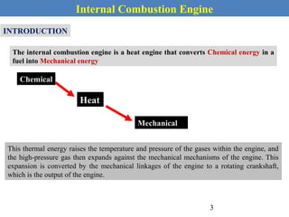
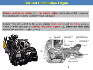
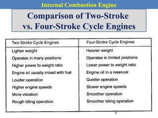
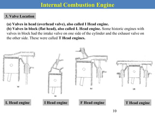
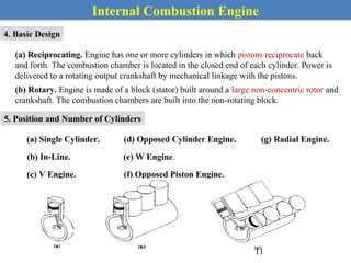
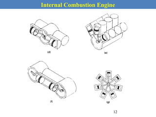
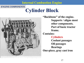
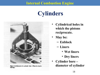
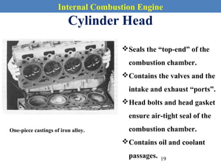
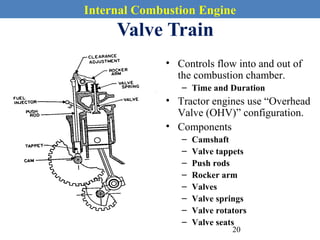


This document provides an overview of internal combustion engines. It begins with an introduction that defines internal combustion engines as heat engines that convert the chemical energy in fuel into mechanical energy. It then covers classifications of engines including by ignition type (spark ignition or compression ignition), engine cycle (four-stroke or two-stroke), valve location, design, cylinder positioning and number, air intake process, fuel input, fuel used, application, and cooling type. The document also discusses important engine components like the cylinder block, cylinders, cylinder head, valve train, pistons, connecting rod, and crankshaft. It concludes with sections on engine cycles, thermochemistry and fuels, emissions and air pollution.


![Electronic fuel injection system [EFI]](https://cdn.slidesharecdn.com/ss_thumbnails/efibilkulfinal-171227111232-thumbnail.jpg?width=640&height=640&fit=bounds)


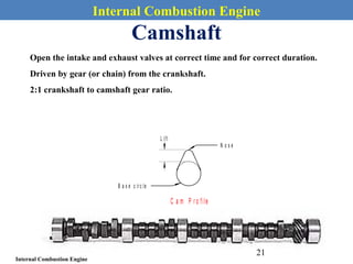
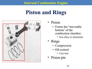
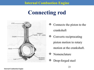
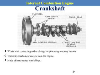
![SBP- IC Engines [Compatibility Mode] (1).pdf](https://cdn.slidesharecdn.com/ss_thumbnails/sbp-icenginescompatibilitymode1-241227102120-3fc3e41a-thumbnail.jpg?width=640&height=640&fit=bounds)


