Downloaded 3,004 times

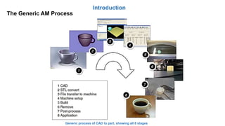
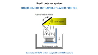


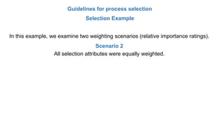
![Guidelines for process selection
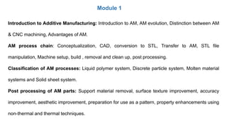
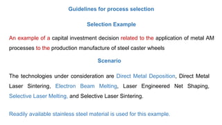
Selection Example
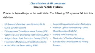
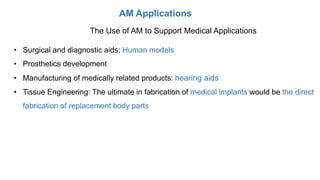
The alternative AM technologies will be evaluated based on 7 attributes that span
a typical range of requirements, as shown in the following section
Ultimate Tensile Strength (UTS): UTS is the maximum stress reached before a material
fractures. Ratio scale [MPa].
Rockwell Hardness C (Hard): Hardness is commonly defined as the resistance of a
material to indentation. Ratio scale [HRc].
Density (Dens.): The density refers to the final density of the part after all processing
steps. This density is proportional to the amount of voids found at the
surface. These voids cause a rough surface finish. Ratio scale [%].](https://image.slidesharecdn.com/module1additivemanufacturing-190128175026/85/Module-1-Additive-Manufacturing-108-320.jpg)
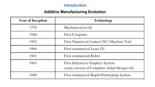
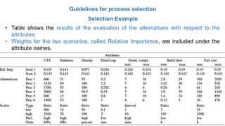
![Guidelines for process selection
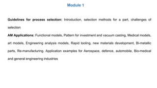
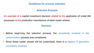
Selection Example
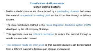
The alternative AM technologies will be evaluated based on 7 attributes that span
a typical range of requirements, as shown in the following section
Detail Capability (DC): The detail capability is the smallest feature size the
technology can make. Ratio scale [mm].
Geometric Complexity (GC): The geometric complexity is the ability of the
technology to build complex parts. It is used to refer to the ability to produce
overhangs. Interval scale (1–10).
Build Time (Time): The build time refers to the time required to fabricate a part, not
including post processing steps. Ratio scale [h].](https://image.slidesharecdn.com/module1additivemanufacturing-190128175026/85/Module-1-Additive-Manufacturing-109-320.jpg)
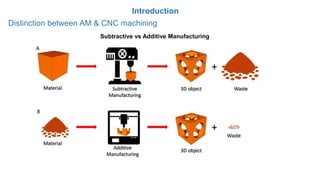
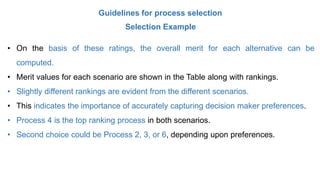
![Guidelines for process selection
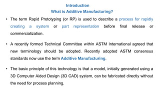
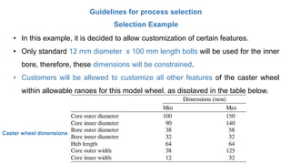
Selection Example
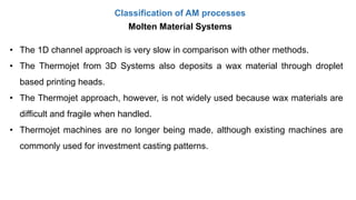
The alternative AM technologies will be evaluated based on 7 attributes that span
a typical range of requirements, as shown in the following section
Part Cost (Cost): The part cost is the cost it takes to build one part with all costs
included. These costs include manufacturing cost, material cost, machine cost,
operation cost, etc. Ratio scale [$].](https://image.slidesharecdn.com/module1additivemanufacturing-190128175026/85/Module-1-Additive-Manufacturing-110-320.jpg)


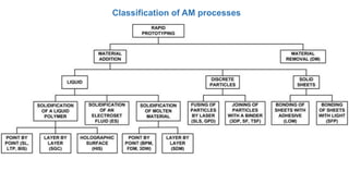
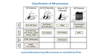
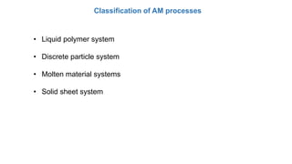
The document describes an additive manufacturing course, including its textbooks, learning outcomes, and modules. Specifically: - The course covers additive manufacturing processes using polymers, powders, and nanomaterials. Students will analyze characterization techniques and describe NC/CNC programming and automation. - Module 1 introduces additive manufacturing, covering its evolution, processes, classifications, post-processing, guidelines for process selection, and applications. - The module discusses the additive manufacturing process chain from CAD to part build and removal, and classifies AM into liquid polymer, particle, molten material, and solid sheet systems.


