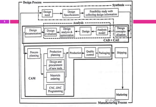
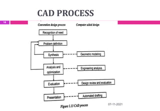
COMPUTER AIDED DESIGN
UNIT 1
FUNDAMENTALS OF COMPUTER GRAPHICS
07-11-2021
1
SYALLABUS
 Product cycle
 Design process
 Sequential and concurrent engineering
 Computer aided design – CAD system architecture
 Computer graphics – co-ordinate systems- 2D and 3D
transformations - homogeneous coordinates
 Line drawing -Clipping- viewing transformation
07-11-2021
2
Introduction to CAD/CAM
07-11-2021
3
 CAD was introduced by Dr. Ivan Sutherland in
1963-1964
 CAD
1. Geometric Modeling
2. Design Engineering
3. Computer Graphics
 CAM
 1. Network
 2. Cad
 3. Manufacturing
Product cycle
 The cycle through which a product goes from
development to retirement is called product life cycle.
 The product cycle starts with developing the product
concept, evolving the design, engineering the product,
manufacturing the part, marketing and servicing.
 The product undergoes the following two main
processes
 Design process
 Manufacturing process
07-11-2021
4
07-11-2021
5
DESIGN PROCESS
 Design is an activity that needs to be well organized and should
take into account all influences that are likely to be responsible
for the success of the product under development.
 The following models are considered in design purpose
 Shigley
 Pahl and Beitz
 Ohsuga
 Earle
07-11-2021
6
Shigley design Process
07-11-2021
7
Pahl and Beitz design Process
07-11-2021
8
Ohsuga design Process
07-11-2021
9
Earle design Process
07-11-2021
10
MORPHOLOGY OF DESIGN
 Morphology design refers to the study of the structure of design
projects.
 It is defined by seven phases and their sub steps.
 Out of seven phases, the first three phases belong to the design
the proposed by Morris Asimow and the remaining four phases
belong to production, distribution, consumption and
retirement.
07-11-2021
11
07-11-2021
12
SEQUENCIAL ENGINEERING
 Three major phases of conventional manufacturing process are
design, process planning and manufacturing.
 All these phases are sequentially carried out.
07-11-2021
13
CONCURRENT ENGINEERING
 It is the methodology of restructuring the product development
activity in a manufacturing organization using cross functional
team approach.
07-11-2021
14
COMPARISION BETWEEN
SEQUENTIAL AND CONCURRENT
ENGINEERING
07-11-2021
15
COMPUTER AIDED DESIGN
 Groover and Zimmers defined “CAD is the technology concerned with
the use of computer systems to assist the creation, modification,
analysis and optimization of a design”.
Roles of CAD in Design
Accurately generated and easily modifiable graphical
representation of the product.
User can nearly view the actual product on the screen, make
any modification to it and present his ideas on screen without
any prototype, during the early stages of the design process.
Complex design analysis in short time. By implementing Finite
Element Analysis (FEA) methods user can perform as follows
07-11-2021
16
Roles of CAD in Design
 Static, dynamic, natural frequency analysis
 Heat transfer analysis
 Fluid flow analysis
 Plastic analysis
 It records and recalls information with consistency and
speed
 Use of Product Data Management (PDM) systems can store
the whole design and processing history of a certain
product for future reuse and upgrade.
07-11-2021
17
CAD PROCESS
07-11-2021
18
APPLICATION OF CAD
 Mechanical engineering
 Civil engineering
 Electrical and electronics engineering
 Textile industry
07-11-2021
19
ADVANTAGES OF CAD
 Easy editing
 High quality
 Compact storage
 3D Drawing
07-11-2021
20
CAD SYSTEM ARCHITECTURE
 It is an early model which was used for the basic geometry
construction and modelling purpose.
 Four major components of CAD System Architecture are
1. Database
2. Operating system
3. Input/output devices
4. User interface
07-11-2021
21
07-11-2021
22
07-11-2021
23
COMPUTER GRAPHICS (CG)
 Computer graphics is a technology which uses the display of the
drawing or the geometric model of the component in CAD.
 It is an extremely effective medium for communication between
users and computers.
 There are two types
1. Passive Computer Graphics
2. Interactive Computer Graphics (IGC)
07-11-2021
24
07-11-2021
25
ADVANTAGES OF COMPUTER
GRAPHICS
 The object drawings can be denoted by its geometric model in
three dimensions. i.e. X, Y, Z coordinates.
 Accurate drawings can be made.
 Sectional drawings can be easily created.
 Modification of geometric model of objects is easy.
 It is easy storage and retrieval of drawings.
07-11-2021
26
APPLICATIONS OF COMPUTER
GRAPHICS
 Paint programs
 Design programs
 Presentation graphics software
 Animation software
 CAD software
 Desktop publishing
 Education and training
 Image processing
07-11-2021
27
CO-ORDINATE SYSTEMS
 In general, there are two types of co-ordinate system
1. Cartesian – Linear distances X,Y and Z
2. Polar – Angles such as θ, α, φ
07-11-2021
28
Left and right handed coordinate
system
07-11-2021
29
2D & 3D
(GEOMETRIC)TRANSFORMATION
 A geometric transformation is an operation that
modifies its shape, size, position, orientation etc.
with respect to its current configuration operating
on the vertices.
 Some of the important transformations are
Translation
Scaling
Rotation
Reflection
Shear
07-11-2021
30
2D & 3D TRASLATION
,
, ,
x y
x
y
x x t y y t
t
x x
t
y y
 
   
  
   

    
   

     
  
P P T
P P T
07-11-2021
31
2D Formula 3D Formula
2D & 3D SCALING
07-11-2021
32
2D Formula 3D Formula
,
0
0
x y
x
y
x x s y y s
s
x x
s
y y
 
   
  
   
  
   

   
 
  
P S P
2D & 3D ROTATION
07-11-2021
33
2D Formula 3D Formula
HOMOGENEOUS TRANSFORMATION
 The three dimensional representation of two
dimensional plane is called as homogeneous
representation and the transformation using
homogeneous representation is called
homogeneous transformation.
07-11-2021
34
HOMOGENEOUS TRANSFORMATION
07-11-2021
35
LINE DRAWING
07-11-2021
36
 Straight line segments are used a great deal in
computer generated pictures. The following criteria
have been stipulated for line drawing displays:
i. Lines should appear straight
ii. Lines should terminate accurately
iii. Lines should have constant density
iv. Line density should be independent of length and angle
v. Line should be drawn rapidly
DDA ALGORITHM
07-11-2021
37
 A popular method uses an algorithm known as
“Digital Differential Analyzer” which generates lines
from their differential equations.
 For a line segment joining two points P1 and P2, a
parametric representation is given by
P(u) =P1+(P2-P1)u
 In terms of x(u) and y(u)
x(u) = x1 + (x2-x1)u
y(u) = y1 + (y2-y1)u
BRESENHAM’S LINE ALGORITHM
07-11-2021
38
 The basic principle of Bresenham’s line algorithms is
to select the optimum location to represents a
straight line.
 To achieve optimum scan, the algorithm always
increments either x or y by one unit depending on
the slope line.
 The increment in the other variable is determined by
examining the distance between the actual line
location and the nearest pixel.
 This distance is called decision variable or error.
CLIPPING
07-11-2021
39
 If any part of the geometry is not inside the
window, it is made invisible by the graphic software
is called clipping.
07-11-2021
40
07-11-2021
41
VIEWING TRANSFORMATIONS
07-11-2021
42
 Displaying an image of a picture involves in
mapping the co-ordinates of the picture into the
appropriate coordinates on the device where the
image is to be displayed.
07-11-2021
43

COMPUTER AIDED DESIGN

  • 1.
    COMPUTER AIDED DESIGN UNIT1 FUNDAMENTALS OF COMPUTER GRAPHICS 07-11-2021 1
  • 2.
    SYALLABUS  Product cycle Design process  Sequential and concurrent engineering  Computer aided design – CAD system architecture  Computer graphics – co-ordinate systems- 2D and 3D transformations - homogeneous coordinates  Line drawing -Clipping- viewing transformation 07-11-2021 2
  • 3.
    Introduction to CAD/CAM 07-11-2021 3 CAD was introduced by Dr. Ivan Sutherland in 1963-1964  CAD 1. Geometric Modeling 2. Design Engineering 3. Computer Graphics  CAM  1. Network  2. Cad  3. Manufacturing
  • 4.
    Product cycle  Thecycle through which a product goes from development to retirement is called product life cycle.  The product cycle starts with developing the product concept, evolving the design, engineering the product, manufacturing the part, marketing and servicing.  The product undergoes the following two main processes  Design process  Manufacturing process 07-11-2021 4
  • 5.
  • 6.
    DESIGN PROCESS  Designis an activity that needs to be well organized and should take into account all influences that are likely to be responsible for the success of the product under development.  The following models are considered in design purpose  Shigley  Pahl and Beitz  Ohsuga  Earle 07-11-2021 6
  • 7.
  • 8.
    Pahl and Beitzdesign Process 07-11-2021 8
  • 9.
  • 10.
  • 11.
    MORPHOLOGY OF DESIGN Morphology design refers to the study of the structure of design projects.  It is defined by seven phases and their sub steps.  Out of seven phases, the first three phases belong to the design the proposed by Morris Asimow and the remaining four phases belong to production, distribution, consumption and retirement. 07-11-2021 11
  • 12.
  • 13.
    SEQUENCIAL ENGINEERING  Threemajor phases of conventional manufacturing process are design, process planning and manufacturing.  All these phases are sequentially carried out. 07-11-2021 13
  • 14.
    CONCURRENT ENGINEERING  Itis the methodology of restructuring the product development activity in a manufacturing organization using cross functional team approach. 07-11-2021 14
  • 15.
    COMPARISION BETWEEN SEQUENTIAL ANDCONCURRENT ENGINEERING 07-11-2021 15
  • 16.
    COMPUTER AIDED DESIGN Groover and Zimmers defined “CAD is the technology concerned with the use of computer systems to assist the creation, modification, analysis and optimization of a design”. Roles of CAD in Design Accurately generated and easily modifiable graphical representation of the product. User can nearly view the actual product on the screen, make any modification to it and present his ideas on screen without any prototype, during the early stages of the design process. Complex design analysis in short time. By implementing Finite Element Analysis (FEA) methods user can perform as follows 07-11-2021 16
  • 17.
    Roles of CADin Design  Static, dynamic, natural frequency analysis  Heat transfer analysis  Fluid flow analysis  Plastic analysis  It records and recalls information with consistency and speed  Use of Product Data Management (PDM) systems can store the whole design and processing history of a certain product for future reuse and upgrade. 07-11-2021 17
  • 18.
  • 19.
    APPLICATION OF CAD Mechanical engineering  Civil engineering  Electrical and electronics engineering  Textile industry 07-11-2021 19
  • 20.
    ADVANTAGES OF CAD Easy editing  High quality  Compact storage  3D Drawing 07-11-2021 20
  • 21.
    CAD SYSTEM ARCHITECTURE It is an early model which was used for the basic geometry construction and modelling purpose.  Four major components of CAD System Architecture are 1. Database 2. Operating system 3. Input/output devices 4. User interface 07-11-2021 21
  • 22.
  • 23.
  • 24.
    COMPUTER GRAPHICS (CG) Computer graphics is a technology which uses the display of the drawing or the geometric model of the component in CAD.  It is an extremely effective medium for communication between users and computers.  There are two types 1. Passive Computer Graphics 2. Interactive Computer Graphics (IGC) 07-11-2021 24
  • 25.
  • 26.
    ADVANTAGES OF COMPUTER GRAPHICS The object drawings can be denoted by its geometric model in three dimensions. i.e. X, Y, Z coordinates.  Accurate drawings can be made.  Sectional drawings can be easily created.  Modification of geometric model of objects is easy.  It is easy storage and retrieval of drawings. 07-11-2021 26
  • 27.
    APPLICATIONS OF COMPUTER GRAPHICS Paint programs  Design programs  Presentation graphics software  Animation software  CAD software  Desktop publishing  Education and training  Image processing 07-11-2021 27
  • 28.
    CO-ORDINATE SYSTEMS  Ingeneral, there are two types of co-ordinate system 1. Cartesian – Linear distances X,Y and Z 2. Polar – Angles such as θ, α, φ 07-11-2021 28
  • 29.
    Left and righthanded coordinate system 07-11-2021 29
  • 30.
    2D & 3D (GEOMETRIC)TRANSFORMATION A geometric transformation is an operation that modifies its shape, size, position, orientation etc. with respect to its current configuration operating on the vertices.  Some of the important transformations are Translation Scaling Rotation Reflection Shear 07-11-2021 30
  • 31.
    2D & 3DTRASLATION , , , x y x y x x t y y t t x x t y y                                  P P T P P T 07-11-2021 31 2D Formula 3D Formula
  • 32.
    2D & 3DSCALING 07-11-2021 32 2D Formula 3D Formula , 0 0 x y x y x x s y y s s x x s y y                               P S P
  • 33.
    2D & 3DROTATION 07-11-2021 33 2D Formula 3D Formula
  • 34.
    HOMOGENEOUS TRANSFORMATION  Thethree dimensional representation of two dimensional plane is called as homogeneous representation and the transformation using homogeneous representation is called homogeneous transformation. 07-11-2021 34
  • 35.
  • 36.
    LINE DRAWING 07-11-2021 36  Straightline segments are used a great deal in computer generated pictures. The following criteria have been stipulated for line drawing displays: i. Lines should appear straight ii. Lines should terminate accurately iii. Lines should have constant density iv. Line density should be independent of length and angle v. Line should be drawn rapidly
  • 37.
    DDA ALGORITHM 07-11-2021 37  Apopular method uses an algorithm known as “Digital Differential Analyzer” which generates lines from their differential equations.  For a line segment joining two points P1 and P2, a parametric representation is given by P(u) =P1+(P2-P1)u  In terms of x(u) and y(u) x(u) = x1 + (x2-x1)u y(u) = y1 + (y2-y1)u
  • 38.
    BRESENHAM’S LINE ALGORITHM 07-11-2021 38 The basic principle of Bresenham’s line algorithms is to select the optimum location to represents a straight line.  To achieve optimum scan, the algorithm always increments either x or y by one unit depending on the slope line.  The increment in the other variable is determined by examining the distance between the actual line location and the nearest pixel.  This distance is called decision variable or error.
  • 39.
    CLIPPING 07-11-2021 39  If anypart of the geometry is not inside the window, it is made invisible by the graphic software is called clipping.
  • 40.
  • 41.
  • 42.
    VIEWING TRANSFORMATIONS 07-11-2021 42  Displayingan image of a picture involves in mapping the co-ordinates of the picture into the appropriate coordinates on the device where the image is to be displayed.
  • 43.