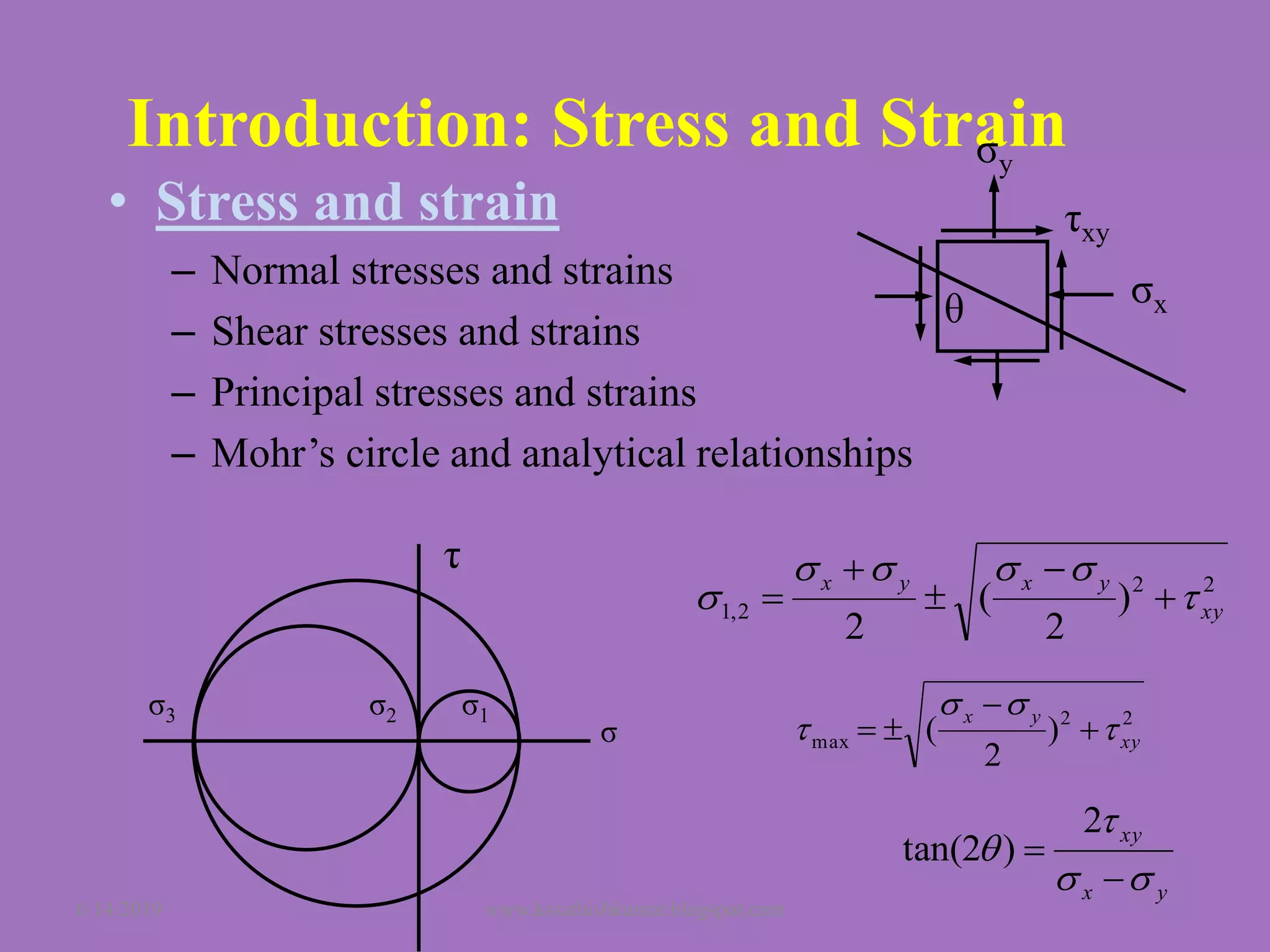
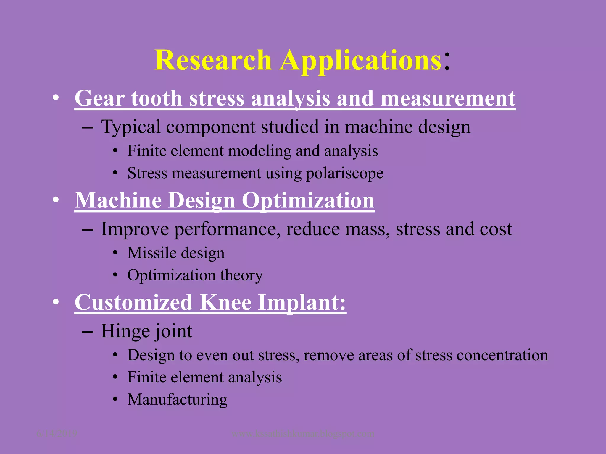
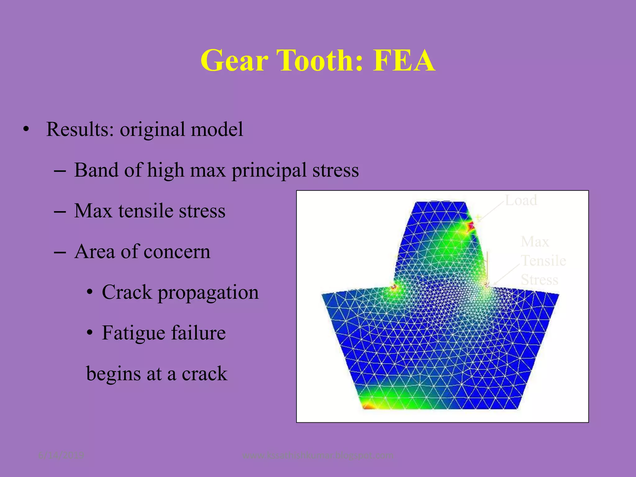
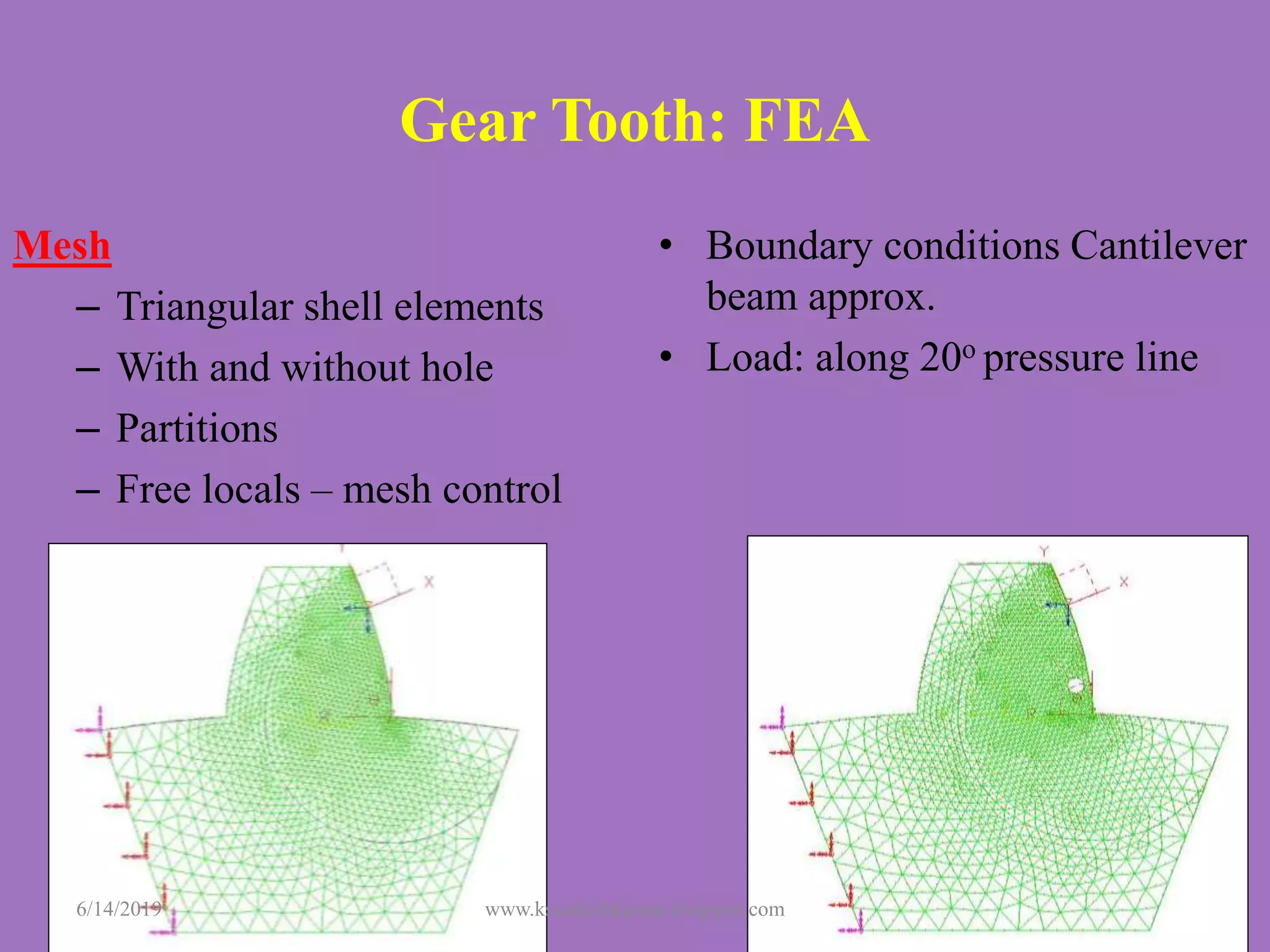
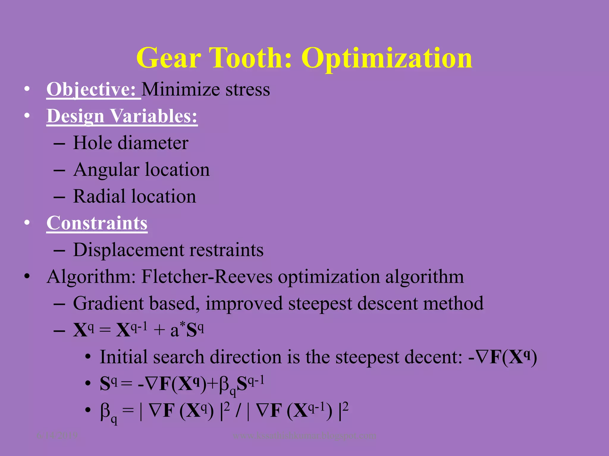
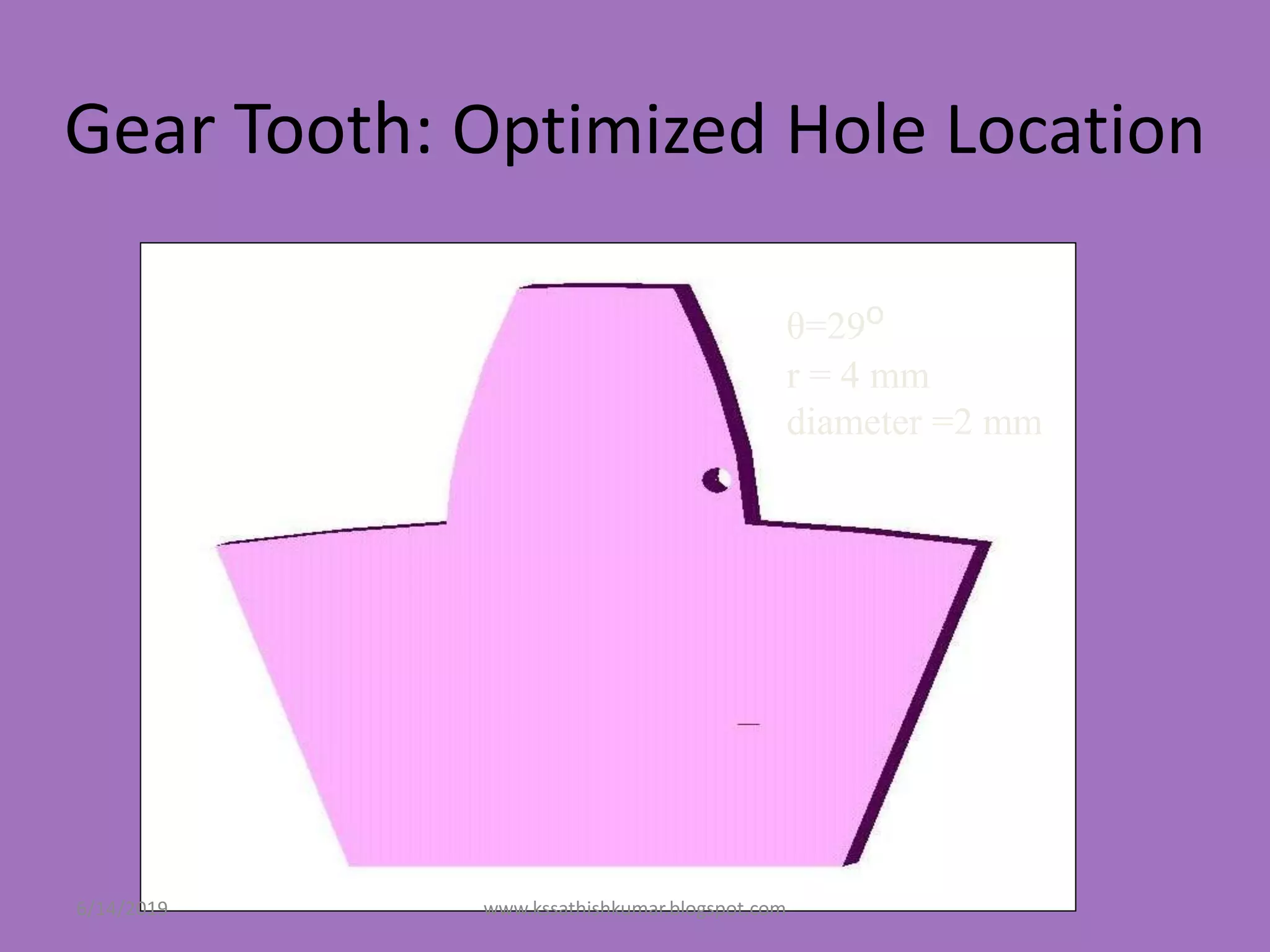
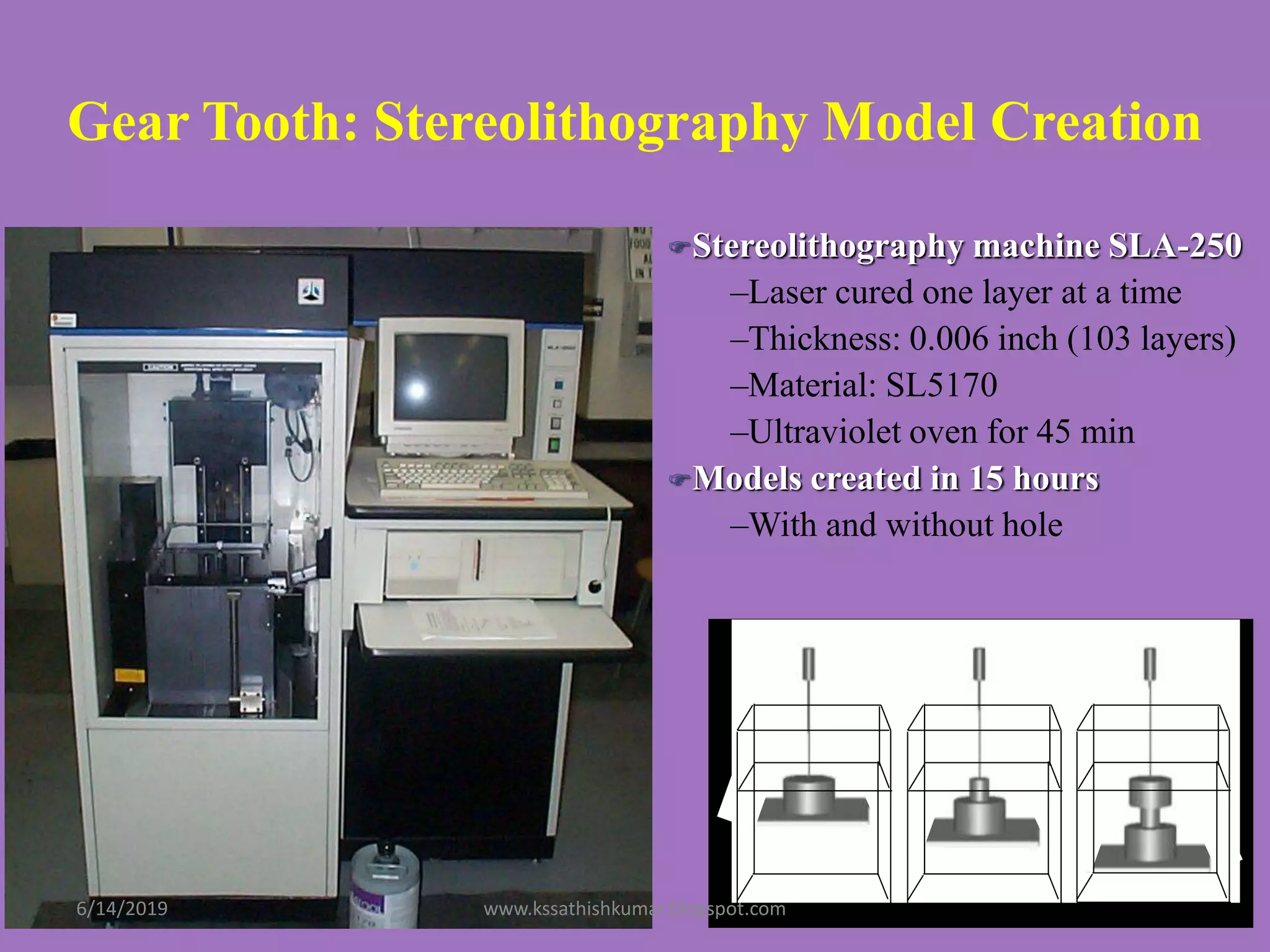
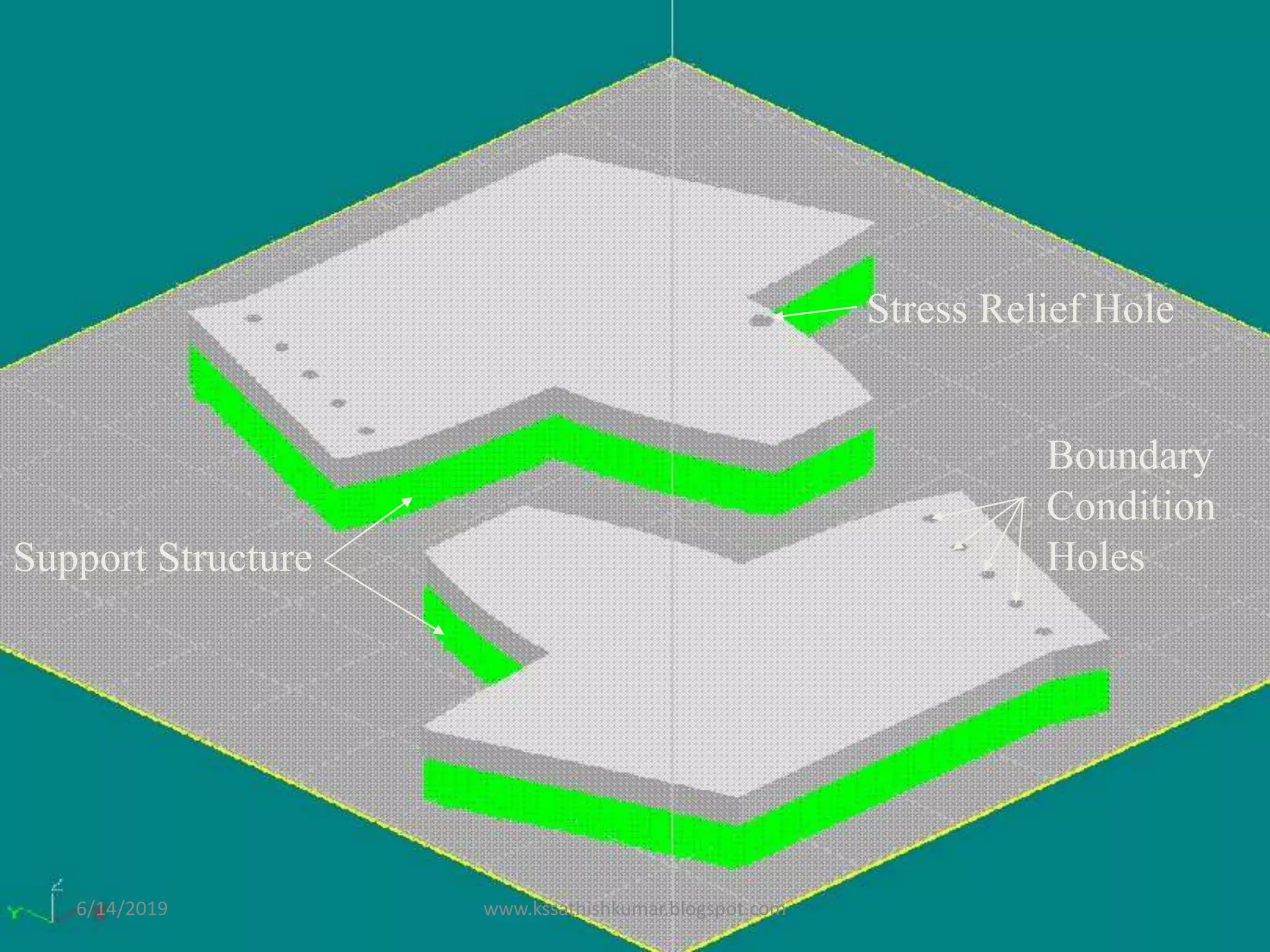
Machine Design
(Introduction)
Presented by
Prof.S.Sathishkumar
Assistant Professor
Department of Mechanical Engineering
Vel Tech Engineering College
Avadi- Chennai-62
6/14/2019 www.kssathishkumar.blogspot.com
Presentation Agenda
• Introduction: What is Machine Design?
• Machine Design: Research Areas
• Research Applications:
– Gear Tooth FEM/FEA and Optimization
– Machine Design Optimization
– Customized Knee Implant: Design, Stress Analysis
and Manufacturing
6/14/2019 www.kssathishkumar.blogspot.com
What is Machine Design?
• Core of Mechanical Engg
– Stress and strain
– Designing for safety
– Static failure theories
– Fatigue failure theories
– Machine elements
– Mechanical material
properties
– Stress Concentrations
– Fracture Mechanics
– Optimization
– Composite Materials
– Manufacturing Processes
– Computer Aided Machine
Design and Analysis
– Measuring Stress and
Strain
6/14/2019 www.kssathishkumar.blogspot.com
• Stress and strain
– Normal stresses and strains
– Shear stresses and strains
– Principal stresses and strains
– Mohr’s circle and analytical relationships
Introduction: Stress and Strain
τ
σ
σ1σ2σ3
22
2,1 )
2
(
2
xy
yxyx


 




22
max )
2
( xy
yx


 


yx
xy





2
)2tan(
θ σx
σy
τxy
6/14/2019 www.kssathishkumar.blogspot.com
Introduction: Static Failure
• Ductile Behavior
– Maximum Shear-Stress Theory (Tresca/Coulomb/Guest
Theory)
– Distortion Energy Theory (von Mises)
• Brittle Behavior (even and uneven materials)
– Coulomb-Mohr Theory
FS
S
σσ
y
31 
FS
S
)σ(σ)σ(σ)σ(σ
2
2
σ
y2
13
2
32
2
21eff 
σ
τ
Compression
test Tension
test
σ1
σ3
Sut, Sut
Sut, -Sut
Sut, -Sut
-Sut, Sut-Suc, Sut
uneven
6/14/2019 www.kssathishkumar.blogspot.com
Introduction: Fatigue Failure
• Alternating and mean stress
• Stress-Life Approach
– High Cycle Fatigue Criteria
– Load amplitude is consistent
– Common for rotating machinery
• Strain-Life Approach
– Low cycle fatigue (<103)
– Variations in loads and high
temperatures
– Common for service machinery
• Fracture Mechanics Approach
– Low cycle fatigue
– Generally used to determine
remaining life of a cracked part
– Paris equation
n
KA
dN
da
)(
n,A: empirical values
K: stress intensity factor

t
103
104 106 107
105
1.0
0.6
0.8
0.4
Corrected endurance limit:
Se=C load C size C surf C temp C reliable Se‘
Corrected fatigue strength
Sf=C load C size C surf C temp C reliabe Sf'
6/14/2019
www.kssathishkumar.blogspot.com
Introduction: Machine Elements
• Springs
• Fasteners
• Bearings
• Shafts
• Gears
Machined Universal
Joint Coiled
6/14/2019 www.kssathishkumar.blogspot.com
Machine Design: Research Areas
• Finite Element Analysis
• Design Optimization
• Biomechanics
• Nanotechnology
• Fracture Mechanics
• Mechanical Material Properties
• Composite Materials
• Designing for Manufacturing
• Welding
6/14/2019 www.kssathishkumar.blogspot.com
Research Applications:
• Gear tooth stress analysis and measurement
– Typical component studied in machine design
• Finite element modeling and analysis
• Stress measurement using polariscope
• Machine Design Optimization
– Improve performance, reduce mass, stress and cost
• Missile design
• Optimization theory
• Customized Knee Implant:
– Hinge joint
• Design to even out stress, remove areas of stress concentration
• Finite element analysis
• Manufacturing
6/14/2019 www.kssathishkumar.blogspot.com
Gear Tooth: Introduction
• Gear is a typical component studied in machine design
• In analyzing the stresses in gears one uses stress/strain and failure theories
• The stresses were measured using a polariscope
• Objective: minimize stress at the root of a gear tooth by introducing a stress
relief hole
• Parameters: location (r, θ) and size of hole
• Analytical model: I-DEAS Master Series
– Solid Model, FEA, Optimization
• Experimental analysis to validate analytical model
– Stereolithography model, Polariscope
6/14/2019 www.kssathishkumar.blogspot.com
Gear Tooth: Two Gears Meshing
6/14/2019 www.kssathishkumar.blogspot.com
Gear Tooth: Two Gears Meshing
6/14/2019 www.kssathishkumar.blogspot.com
Gear Tooth: Solid Model Creation
• Involute and gear created in I-DEAS
• Simplifications: no fillets, one tooth
– Pitch Diameter = 360 mm
– Number of teeth = 30
– Pressure angle = 20o
– Addendum = 12 mm
– Dedendum = 15 mm
– Gear thickness = 5 mm
– Circular tooth thickness = 18.85 mm
6/14/2019 www.kssathishkumar.blogspot.com
Gear Tooth: FEA
• Results: original model
– Band of high max principal stress
– Max tensile stress
– Area of concern
• Crack propagation
• Fatigue failure
begins at a crack
Load
Max
Tensile
Stress
6/14/2019 www.kssathishkumar.blogspot.com
Gear Tooth: FEA
Mesh
– Triangular shell elements
– With and without hole
– Partitions
– Free locals – mesh control
• Boundary conditions Cantilever
beam approx.
• Load: along 20o pressure line
6/14/2019 www.kssathishkumar.blogspot.com
Gear Tooth: Optimization
• Objective: Minimize stress
• Design Variables:
– Hole diameter
– Angular location
– Radial location
• Constraints
– Displacement restraints
• Algorithm: Fletcher-Reeves optimization algorithm
– Gradient based, improved steepest descent method
– Xq = Xq-1 + a*Sq
• Initial search direction is the steepest decent: -F(Xq)
• Sq = -F(Xq)+qSq-1
• q = | F (Xq) |2 / | F (Xq-1) |2
6/14/2019 www.kssathishkumar.blogspot.com
Gear Tooth: Optimized Hole Location
θ=29o
r = 4 mm
diameter =2 mm
6/14/2019 www.kssathishkumar.blogspot.com
Gear Tooth: Stereolithography Model Creation
Stereolithography machine SLA-250
–Laser cured one layer at a time
–Thickness: 0.006 inch (103 layers)
–Material: SL5170
–Ultraviolet oven for 45 min
Models created in 15 hours
–With and without hole
6/14/2019 www.kssathishkumar.blogspot.com
Boundary
Condition
Holes
Stress Relief Hole
Support Structure
6/14/2019 www.kssathishkumar.blogspot.com
Gear Tooth: Experimental Setup
• Experimental study to verify FEA
• A flange with holes for mounting was added to the models to
hold the parts in place in the polariscope
– Compression force was applied
– Bracket was used to distribute the force
• Circular polariscope dark field was used
– Used to analyze stress in 2D models
6/14/2019 www.kssathishkumar.blogspot.com
Gear Tooth: Circular Polariscope
6/14/2019 www.kssathishkumar.blogspot.com
Gear Tooth: Isochromatic Fringes
• Extinction of light of a particular wave lengths (colored light)
• Determines the magnitude of the stress difference
– n = hc/*(1- 2)
• n: fringe order
• hc/: constants
• 1- 2: stress difference
• black yellow red | blue yellow red | green yellow red | green
yellow red | g y r | ...
6/14/2019 www.kssathishkumar.blogspot.com
Gear Tooth: Comparison of Fringes
With and Without Hole
6/14/2019 www.kssathishkumar.blogspot.com
• Designing parts for performance and mass production
– Mass reduction
– Stress reduction
– Cost reduction
– Performance improvement
– Machine design components or systems
• Missile design
– Optimization theory and application
– Academic vs. industrial design optimization
Machine Design Optimization:
Optimization of a Missile
6/14/2019 www.kssathishkumar.blogspot.com
Machine Design Optimization: Basics
• Optimization Algorithms
– Gradient-based Algorithms
– Genetic Algorithms
• MDO Formulations
– Discipline communication
• Approximations
– Artificial Neural Networks
– Design of Experiment
– Response Surface Approximations
– Taylor Series Approximations
6/14/2019 www.kssathishkumar.blogspot.com
Machine Design Optimization:
Academic vs. Industrial Problems
• Design Goal
– Maximize range
• Key design parameters
– Mid body diameter
– Mid body length
– Nose length
– Case length
– Web fraction (difference of the
outer and inner radii to the inner radius)
– Expansion ratio (the ratio of the
exit area to the throat area of the nozzle)
– Gamma (angle of the
velocity vector)
• Constraints
– Weight
– Center of gravity
– Total missile length
– Cost
– Nose finess ratio
– Minimum Mach number
6/14/2019 www.kssathishkumar.blogspot.com
Knee Implant Example
• Knee joint is a hinge joint
• Stress analysis
• Stress concentrations
• Wear of the implant
• Manufacturing
– Rapid Prototyping
– Investment Casting
6/14/2019 www.kssathishkumar.blogspot.com
Knee Implant Example: Need for
Customization
• >0.5 million orthopedic implant surgeries conducted each year in the
US
– Number increasing
• Increasing life span
• Higher activity level
• Problems associated with implants are proportionally increasing
– Use of standard implants leads to removal of valuable bone
material
– Revisions are primarily due to loosening of implants
• Poor fit – only a few types and sizes are available
• Stress concentrations affect bone remodeling
6/14/2019 www.kssathishkumar.blogspot.com
Knee Implant Example: Current Design
Cancellous
Bone
Cortical
Bone
Tibial
PlateauStem
Sharp edges
Medial cross section of
femoral component
6/14/2019 www.kssathishkumar.blogspot.com
Knee Implant Example : Manufacturing
 Rapid Prototyping
–Laser cures one layer at a time
–Thickness: 0.006 inch
 Investment Casting
CAD model to Stereolithography model.
–Eliminates costly low-production-run wax
pattern tooling.
6/14/2019 www.kssathishkumar.blogspot.com
Knee Implant Example:
Manufacturing – Investment Casting
6/14/2019 www.kssathishkumar.blogspot.com
Knee Implant Example:
Manufacturing – Investment Casting
6/14/2019 www.kssathishkumar.blogspot.com
Knee Implant Example:
Manufacturing – Investment Casting
6/14/2019 www.kssathishkumar.blogspot.com
Further Exposure about Machine Design Will be
Continue Upcoming Presentation
If You Have Any Queries Feel Free Contact us
E-Mail :
sathishkumar@veltechengg.com
Wish You Happy Learning
6/14/2019 www.kssathishkumar.blogspot.com

Mechanical Machine Design -Introduction

  • 1.
    Machine Design (Introduction) Presented by Prof.S.Sathishkumar AssistantProfessor Department of Mechanical Engineering Vel Tech Engineering College Avadi- Chennai-62 6/14/2019 www.kssathishkumar.blogspot.com
  • 2.
    Presentation Agenda • Introduction:What is Machine Design? • Machine Design: Research Areas • Research Applications: – Gear Tooth FEM/FEA and Optimization – Machine Design Optimization – Customized Knee Implant: Design, Stress Analysis and Manufacturing 6/14/2019 www.kssathishkumar.blogspot.com
  • 3.
    What is MachineDesign? • Core of Mechanical Engg – Stress and strain – Designing for safety – Static failure theories – Fatigue failure theories – Machine elements – Mechanical material properties – Stress Concentrations – Fracture Mechanics – Optimization – Composite Materials – Manufacturing Processes – Computer Aided Machine Design and Analysis – Measuring Stress and Strain 6/14/2019 www.kssathishkumar.blogspot.com
  • 4.
    • Stress andstrain – Normal stresses and strains – Shear stresses and strains – Principal stresses and strains – Mohr’s circle and analytical relationships Introduction: Stress and Strain τ σ σ1σ2σ3 22 2,1 ) 2 ( 2 xy yxyx         22 max ) 2 ( xy yx       yx xy      2 )2tan( θ σx σy τxy 6/14/2019 www.kssathishkumar.blogspot.com
  • 5.
    Introduction: Static Failure •Ductile Behavior – Maximum Shear-Stress Theory (Tresca/Coulomb/Guest Theory) – Distortion Energy Theory (von Mises) • Brittle Behavior (even and uneven materials) – Coulomb-Mohr Theory FS S σσ y 31  FS S )σ(σ)σ(σ)σ(σ 2 2 σ y2 13 2 32 2 21eff  σ τ Compression test Tension test σ1 σ3 Sut, Sut Sut, -Sut Sut, -Sut -Sut, Sut-Suc, Sut uneven 6/14/2019 www.kssathishkumar.blogspot.com
  • 6.
    Introduction: Fatigue Failure •Alternating and mean stress • Stress-Life Approach – High Cycle Fatigue Criteria – Load amplitude is consistent – Common for rotating machinery • Strain-Life Approach – Low cycle fatigue (<103) – Variations in loads and high temperatures – Common for service machinery • Fracture Mechanics Approach – Low cycle fatigue – Generally used to determine remaining life of a cracked part – Paris equation n KA dN da )( n,A: empirical values K: stress intensity factor  t 103 104 106 107 105 1.0 0.6 0.8 0.4 Corrected endurance limit: Se=C load C size C surf C temp C reliable Se‘ Corrected fatigue strength Sf=C load C size C surf C temp C reliabe Sf' 6/14/2019 www.kssathishkumar.blogspot.com
  • 7.
    Introduction: Machine Elements •Springs • Fasteners • Bearings • Shafts • Gears Machined Universal Joint Coiled 6/14/2019 www.kssathishkumar.blogspot.com
  • 8.
    Machine Design: ResearchAreas • Finite Element Analysis • Design Optimization • Biomechanics • Nanotechnology • Fracture Mechanics • Mechanical Material Properties • Composite Materials • Designing for Manufacturing • Welding 6/14/2019 www.kssathishkumar.blogspot.com
  • 9.
    Research Applications: • Geartooth stress analysis and measurement – Typical component studied in machine design • Finite element modeling and analysis • Stress measurement using polariscope • Machine Design Optimization – Improve performance, reduce mass, stress and cost • Missile design • Optimization theory • Customized Knee Implant: – Hinge joint • Design to even out stress, remove areas of stress concentration • Finite element analysis • Manufacturing 6/14/2019 www.kssathishkumar.blogspot.com
  • 10.
    Gear Tooth: Introduction •Gear is a typical component studied in machine design • In analyzing the stresses in gears one uses stress/strain and failure theories • The stresses were measured using a polariscope • Objective: minimize stress at the root of a gear tooth by introducing a stress relief hole • Parameters: location (r, θ) and size of hole • Analytical model: I-DEAS Master Series – Solid Model, FEA, Optimization • Experimental analysis to validate analytical model – Stereolithography model, Polariscope 6/14/2019 www.kssathishkumar.blogspot.com
  • 11.
    Gear Tooth: TwoGears Meshing 6/14/2019 www.kssathishkumar.blogspot.com
  • 12.
    Gear Tooth: TwoGears Meshing 6/14/2019 www.kssathishkumar.blogspot.com
  • 13.
    Gear Tooth: SolidModel Creation • Involute and gear created in I-DEAS • Simplifications: no fillets, one tooth – Pitch Diameter = 360 mm – Number of teeth = 30 – Pressure angle = 20o – Addendum = 12 mm – Dedendum = 15 mm – Gear thickness = 5 mm – Circular tooth thickness = 18.85 mm 6/14/2019 www.kssathishkumar.blogspot.com
  • 14.
    Gear Tooth: FEA •Results: original model – Band of high max principal stress – Max tensile stress – Area of concern • Crack propagation • Fatigue failure begins at a crack Load Max Tensile Stress 6/14/2019 www.kssathishkumar.blogspot.com
  • 15.
    Gear Tooth: FEA Mesh –Triangular shell elements – With and without hole – Partitions – Free locals – mesh control • Boundary conditions Cantilever beam approx. • Load: along 20o pressure line 6/14/2019 www.kssathishkumar.blogspot.com
  • 16.
    Gear Tooth: Optimization •Objective: Minimize stress • Design Variables: – Hole diameter – Angular location – Radial location • Constraints – Displacement restraints • Algorithm: Fletcher-Reeves optimization algorithm – Gradient based, improved steepest descent method – Xq = Xq-1 + a*Sq • Initial search direction is the steepest decent: -F(Xq) • Sq = -F(Xq)+qSq-1 • q = | F (Xq) |2 / | F (Xq-1) |2 6/14/2019 www.kssathishkumar.blogspot.com
  • 17.
    Gear Tooth: OptimizedHole Location θ=29o r = 4 mm diameter =2 mm 6/14/2019 www.kssathishkumar.blogspot.com
  • 18.
    Gear Tooth: StereolithographyModel Creation Stereolithography machine SLA-250 –Laser cured one layer at a time –Thickness: 0.006 inch (103 layers) –Material: SL5170 –Ultraviolet oven for 45 min Models created in 15 hours –With and without hole 6/14/2019 www.kssathishkumar.blogspot.com
  • 19.
    Boundary Condition Holes Stress Relief Hole SupportStructure 6/14/2019 www.kssathishkumar.blogspot.com
  • 20.
    Gear Tooth: ExperimentalSetup • Experimental study to verify FEA • A flange with holes for mounting was added to the models to hold the parts in place in the polariscope – Compression force was applied – Bracket was used to distribute the force • Circular polariscope dark field was used – Used to analyze stress in 2D models 6/14/2019 www.kssathishkumar.blogspot.com
  • 21.
    Gear Tooth: CircularPolariscope 6/14/2019 www.kssathishkumar.blogspot.com
  • 22.
    Gear Tooth: IsochromaticFringes • Extinction of light of a particular wave lengths (colored light) • Determines the magnitude of the stress difference – n = hc/*(1- 2) • n: fringe order • hc/: constants • 1- 2: stress difference • black yellow red | blue yellow red | green yellow red | green yellow red | g y r | ... 6/14/2019 www.kssathishkumar.blogspot.com
  • 23.
    Gear Tooth: Comparisonof Fringes With and Without Hole 6/14/2019 www.kssathishkumar.blogspot.com
  • 24.
    • Designing partsfor performance and mass production – Mass reduction – Stress reduction – Cost reduction – Performance improvement – Machine design components or systems • Missile design – Optimization theory and application – Academic vs. industrial design optimization Machine Design Optimization: Optimization of a Missile 6/14/2019 www.kssathishkumar.blogspot.com
  • 25.
    Machine Design Optimization:Basics • Optimization Algorithms – Gradient-based Algorithms – Genetic Algorithms • MDO Formulations – Discipline communication • Approximations – Artificial Neural Networks – Design of Experiment – Response Surface Approximations – Taylor Series Approximations 6/14/2019 www.kssathishkumar.blogspot.com
  • 26.
    Machine Design Optimization: Academicvs. Industrial Problems • Design Goal – Maximize range • Key design parameters – Mid body diameter – Mid body length – Nose length – Case length – Web fraction (difference of the outer and inner radii to the inner radius) – Expansion ratio (the ratio of the exit area to the throat area of the nozzle) – Gamma (angle of the velocity vector) • Constraints – Weight – Center of gravity – Total missile length – Cost – Nose finess ratio – Minimum Mach number 6/14/2019 www.kssathishkumar.blogspot.com
  • 27.
    Knee Implant Example •Knee joint is a hinge joint • Stress analysis • Stress concentrations • Wear of the implant • Manufacturing – Rapid Prototyping – Investment Casting 6/14/2019 www.kssathishkumar.blogspot.com
  • 28.
    Knee Implant Example:Need for Customization • >0.5 million orthopedic implant surgeries conducted each year in the US – Number increasing • Increasing life span • Higher activity level • Problems associated with implants are proportionally increasing – Use of standard implants leads to removal of valuable bone material – Revisions are primarily due to loosening of implants • Poor fit – only a few types and sizes are available • Stress concentrations affect bone remodeling 6/14/2019 www.kssathishkumar.blogspot.com
  • 29.
    Knee Implant Example:Current Design Cancellous Bone Cortical Bone Tibial PlateauStem Sharp edges Medial cross section of femoral component 6/14/2019 www.kssathishkumar.blogspot.com
  • 30.
    Knee Implant Example: Manufacturing  Rapid Prototyping –Laser cures one layer at a time –Thickness: 0.006 inch  Investment Casting CAD model to Stereolithography model. –Eliminates costly low-production-run wax pattern tooling. 6/14/2019 www.kssathishkumar.blogspot.com
  • 31.
    Knee Implant Example: Manufacturing– Investment Casting 6/14/2019 www.kssathishkumar.blogspot.com
  • 32.
    Knee Implant Example: Manufacturing– Investment Casting 6/14/2019 www.kssathishkumar.blogspot.com
  • 33.
    Knee Implant Example: Manufacturing– Investment Casting 6/14/2019 www.kssathishkumar.blogspot.com
  • 34.
    Further Exposure aboutMachine Design Will be Continue Upcoming Presentation If You Have Any Queries Feel Free Contact us E-Mail : sathishkumar@veltechengg.com Wish You Happy Learning 6/14/2019 www.kssathishkumar.blogspot.com
  • 35.