The raster data model divides a geographic area into a grid of cells or pixels that represent attribute values. Each cell has a specific resolution depending on the real world area it represents. Common types of raster data include satellite imagery, digital elevation models (DEMs), digital orthophotos, scanned maps, and graphic files. Raster data is stored using different structures like cell-by-cell encoding, run-length encoding, and quadtree encoding to reduce storage requirements. Raster data can be projected and integrated with vector data for analysis and display in GIS.
This presentation is about the raster and vector data in GIS which is important and costly as well, through the presentation we will learn about both type of data.
Introduction to GIS - Basic spatial concepts - Coordinate Systems - GIS and Information Systems – Definitions – History of GIS - Components of a GIS – Hardware, Software, Data, People, Methods – Proprietary and open source Software - Types of data – Spatial, Attribute data- types of attributes – scales/ levels of measurements.
DEFINITION :
GIS is a powerful set of tools for collecting, storing , retrieving at will, transforming and displaying spatial data from the real world for a particular set of purposes
APPLICATION AREAS OF GIS
Agriculture
Business
Electric/Gas utilities
Environment
Forestry
Geology
Hydrology
Land-use planning
Local government
Mapping
11. Military
12. Risk management
13. Site planning
14. Transportation
15. Water / Waste water industry
COMPONENTS OF GIS
DATA INPUT
SPATIAL DATA MODEL
Data Model:
It describes in an abstract way how the data is represented in an information system or in DBMS
Spatial Data Model :
The models or abstractions of reality that are intended to have some similarity with selected aspects of the real world
Creation of analogue and digital spatial data sets involves seven levels of model development and abstraction
SPATIAL DATA MODEL
Conceptual model : A view of reality
Analog model : Human conceptualization leads to analogue abstraction
Spatial data models : Formalization of analogue abstractions without any conventions
Database model : How the data are recorded in the computer
Physical computational model : Particular representation of the data structures in computer memory
Data manipulation model : Accepted axioms and rules for handling the data
SPATIAL DATA MODEL
SPATIAL DATA MODEL
Objects on the earth surface are shown as continuous and discrete objects in spatial data models
Types of data models
Raster data model
vector data models
RASTER DATA MODEL
Basic Elements :
Extent
Rows
Columns
Origin
Orientation
Resolution: pixel = grain = grid cell
Ex: Bit Map Image (BMP),Joint Photographic Expert Group (JPEG), Portable Network Graphics(PNG) etc
RASTER DATA MODEL
VECTOR DATA MODEL
Basic Elements:
Location (x,y) or (x,y,z)
Explicit, i.e. pegged to a coordinate system
Different coordinate system (and precision) require different values
o e.g. UTM as integer (but large)
o Lat, long as two floating point numbers +/-
Points are used to build more complex features
Ex: Auto CAD Drawing File(DWG), Data Interchange(exchange) File(DXF), Vector Product Format (VPF) etc
VECTOR DATA MODEL
RASTER vs VECTORRaster is faster but Vector is corrector
TESSELLATIONS OF CONTINUOUS FIELDS
Triangular Irregular Network: (TIN)
TIN is a vector data structure for representing geographical information that is continuous
Digital elevation model
TIN is generally used to create Digital Elevation Model (DEM)
DIGITAL ELEVATION MODEL
DATA STRUCTURES
Data structure tells about how the data is stored
Data organization in raster data structures
Each cell is referenced directly
Each overlay Is referenced directly
Each mapping unit is referenced directly
Each overlay is separate file with general header
Topics:
1. Introduction to GIS
2. Components of GIS
3. Types of Data
4. Spatial Data
5. Non-Spatial Data
6. GIS Operations
7. Coordinate Systems
8. Datum
9. Map Projections
10. Raster Data Compression Techniques
11. GIS Software
12. Free GIS Data Resources
Digital Elevation Model (DEM) is the digital representation of the land surface elevation with respect to any reference datum. DEM is frequently used to refer to any digital representation of a topographic surface. DEM is the simplest form of digital representation of topography. GIS applications depend mainly on DEMs, today.
A geographic information system (GIS) is a system designed to capture, store, manipulate, analyze, manage, and present all types of geographical data. The acronym GIS is sometimes used for geographical information science or geospatial information studies to refer to the academic discipline or career of working with geographic information systems and is a large domain within the broader academic discipline of Geoinformatics. In the simplest terms, GIS is the merging of cartography, statistical analysis, and computer science technology.
This is presentation is intended for middle school students. It provides a short introduction to GIS and how to use GIS in the real-world.
ArcGIS Explorer is the software used to demonstrate concepts.
45 minutes + 15 minutes demo
Download ArcGIS Explorer here...
http://www.esri.com/software/arcgis/explorer/
IJRET : International Journal of Research in Engineering and Technology is an international peer reviewed, online journal published by eSAT Publishing House for the enhancement of research in various disciplines of Engineering and Technology. The aim and scope of the journal is to provide an academic medium and an important reference for the advancement and dissemination of research results that support high-level learning, teaching and research in the fields of Engineering and Technology. We bring together Scientists, Academician, Field Engineers, Scholars and Students of related fields of Engineering and Technology
With the onslaught of multimedia in the near past, there has been a tremendous increase in the uses of images. A very good example of which is the web on which most of the documents contain images. Other than this the images are being used in other applications like weather forecasting, medical diagnosis, police department. In R-Tree implementation of image database, images are made available to the program which are then stores in the database. The image database is presented using R-tree and the database is stored in separate file .This R-tree implementation results in both update as well as efficient retrieval of images from hard disk [1][2][4]. We use the similarity based retrieval feature to retrieve the required number of similar images being inquired by the user [3][5][6]. Distance matrix approach is used to find similarity of images [7]. Sobel edge detection algorithm is used to form sketches. If sketch of image is entered for similarity based retrieval, then sketches of stored images are formed and these sketches are compared with input image (sketch) using distance matrix approach[8][9].
International Journal of Engineering Research and Applications (IJERA) is an open access online peer reviewed international journal that publishes research and review articles in the fields of Computer Science, Neural Networks, Electrical Engineering, Software Engineering, Information Technology, Mechanical Engineering, Chemical Engineering, Plastic Engineering, Food Technology, Textile Engineering, Nano Technology & science, Power Electronics, Electronics & Communication Engineering, Computational mathematics, Image processing, Civil Engineering, Structural Engineering, Environmental Engineering, VLSI Testing & Low Power VLSI Design etc.
Target Detection by Fuzzy Gustafson-Kessel AlgorithmCSCJournals
Many commercially available radar systems offer a range of filter options but the problem of clutter rejection for target detection is still present in a number of situations. Rejection of clutter and detection of targets from radar captured data is a challenging task. Raw data captured by radar are not always scaled. A normalization technique has been proposed which transforms the radar captured data into 8 bit. As 8 bit data is easy to analyze and visualize. A modification on Fuzzy c-means has been done by developing Fuzzy Gustafson–Kessel (FGK) algorithm and the result shows robustness of this proposed method.
The French Revolution, which began in 1789, was a period of radical social and political upheaval in France. It marked the decline of absolute monarchies, the rise of secular and democratic republics, and the eventual rise of Napoleon Bonaparte. This revolutionary period is crucial in understanding the transition from feudalism to modernity in Europe.
For more information, visit-www.vavaclasses.com
Francesca Gottschalk - How can education support child empowerment.pptxEduSkills OECD
Francesca Gottschalk from the OECD’s Centre for Educational Research and Innovation presents at the Ask an Expert Webinar: How can education support child empowerment?
Read| The latest issue of The Challenger is here! We are thrilled to announce that our school paper has qualified for the NATIONAL SCHOOLS PRESS CONFERENCE (NSPC) 2024. Thank you for your unwavering support and trust. Dive into the stories that made us stand out!
Honest Reviews of Tim Han LMA Course Program.pptxtimhan337
Personal development courses are widely available today, with each one promising life-changing outcomes. Tim Han’s Life Mastery Achievers (LMA) Course has drawn a lot of interest. In addition to offering my frank assessment of Success Insider’s LMA Course, this piece examines the course’s effects via a variety of Tim Han LMA course reviews and Success Insider comments.
Instructions for Submissions thorugh G- Classroom.pptxJheel Barad
This presentation provides a briefing on how to upload submissions and documents in Google Classroom. It was prepared as part of an orientation for new Sainik School in-service teacher trainees. As a training officer, my goal is to ensure that you are comfortable and proficient with this essential tool for managing assignments and fostering student engagement.
Palestine last event orientationfvgnh .pptxRaedMohamed3
An EFL lesson about the current events in Palestine. It is intended to be for intermediate students who wish to increase their listening skills through a short lesson in power point.
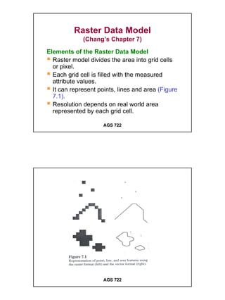
1. Raster Data Model
(Chang’s Chapter 7)
Elements of the Raster Data Model
Raster model divides the area into grid cells
or pixel.
Each grid cell is filled with the measured
attribute values.
It can represent points, lines and area (Figure
7.1).
Resolution depends on real world area
represented by each grid cell.
AGS 722
AGS 722
1
2. Raster Data Model
The larger the area represented, the lower
the resolution of data.
Cells are identified by their positions in the
grid.
Raster data is geo-referenced by:
• Real world coordinates of the reference
point
• Cell size in real world distance
• Use the upper-left or lower-left corner of
grid as the reference point.
AGS 722
IDRISI Metadata
AGS 722
2
3. Raster Data Model
Storage requirement is high.
Ex: If the area is 100 km x 100 km and cell
size is 10 m. It needs 10,000 rows x 10,000
columns or 100,000,000 pixels.
If one byte is used per pixel, it requires 100
MB storage
AGS 722
Types of Raster Data
1. Satellite Imagery
Remotely sensed satellite data are
recorded in raster format.
Spatial resolution varies:
• 30 m. for Landsat 4 and 5 (use the
Thematic Mapper scanner), and
Landsat 7 (use Enhanced Thematic
Mapper-Plus, ETM+ scanner).
AGS 722
3
4. • 20 m. for SPOT images (Multi-spectral
sensor), and 10 m. for SPOT
Panchromatic sensor).
• 4 m. and 1 m. for IKONOS Multi-spectral
and Panchromatic images respectively.
The pixel value in a satellite image represents
light energy reflected or emitted from the
Earth’s surface.
AGS 722
The measurement of light energy is based on
electromagnetic spectrum.
Panchromatic images are comprised of a
single spectral band.
Multi-spectral images have multiple bands.
– Landsat TM has 7 band.
Land use, land cover and hydrography can
be classified from image processing system.
Satellite images can be diaplayed in black
and white or in color.
AGS 722
4
6. 2. Digital Elevation Models (DEM)
DEM consists of an array of uniformly spaced
elevation data.
DEM are produced from:
– a stereoplotter and aerial photograph with
overlapping areas.
– Satellite imagery such as SPOT stereo
model using special software.
AGS 722
3. Digital Orthophotos
Prepared from aerial photograph or other
remotely sensed data.
Displacement caused by camera tilt and
terrain relief has been removed.
They are geo-referenced and can be
registered with topographic and other maps.
AGS 722
6
7. Digital Orthophoto
AGS 722
4. Binary Scanned Files
Scanned image containing values of 1 and 0.
Maps to be digitized are typically scanned at
300 or 400 dpi (dots per inch).
5. Graphic Files
Maps, photographs and images can be stored
as digital graphic files.
– e.g. TIFF (Tagged Image File Format), GIF
(Graphic Interchangeable Format), JPEG
(Joint Photographic Exports Group), etc.
– GeoTIFF is a geo-referenced version of
TIFF format.
AGS 722
7
8. Raster Data Structure
Refers to storage of raster data so that
it can be processed by the computer.
Cell-by Cell Encoding
A raster model is stored as a matrix.
Its cell values are written into a file by
row and column. (Figure 7.2)
Ideal to store the cell values that
change continuously, e.g.,DEM.
AGS 722
AGS 722
8
9. For multi-spectral satellite image, each
cell has more than one value, data are
stored in either of the following formats.
– The band interleaved by line (.bil):
this method stores the 1st value of
every row sequentially, followed by
the second value of every row, and so
on in one image.
AGS 722
Multi-band Satellite Data Structure
.bsq
.bil
Figure 7.x
.bip
AGS 722
9
10. The Band Sequential (.bsq) method:
stores values of each band sequentially
in one image.
The Band Interleave by Pixel (.bip): each
row of an image is stored sequentially,
row 1 all bands, row 2 all bands, and so
on.
(See Figure 7.x)
AGS 722
Multi-band Satellite Data Structure
.bsq
.bil
Figure 7.x
.bip
AGS 722
10
11. Run-length Encoding
Records the cells by row and by group
Each group includes a cell value and the
number of cells with that value.
If all cells in a row contain the same value,
only one group is recorded, hence save
computer memory.
See Figure 7.3.
AGS 722
AGS 722
11
12. Chain Code Method
Represent the boundary of a region by using
a series of cardinal directions and cells.
– Ex: N1 means moving north by 1 cell,
S4 means moving south by 4 cells.
See Figure 7.4
AGS 722
AGS 722
12
13. Block Code Method
Uses square blocks to represent the region.
– A unit square represents 1 cell.
– 4-square block represents 2 x 2 cells
– 9-square block represents 3 x 3 cells, and
so on.
Each square block is coded only with the
location of a cell (lower left of the block), and
the side length of the block.
See Figure 7.5
AGS 722
AGS 722
13
14. Quad Tree Method
Uses recursive decomposition to divide a grid
into a hierarchy of quadrants. (Figure 7.6).
A quadrant having cells with the same value
will not be sub-divided, and it is stored as a
leaf node.
Leaf nodes are coded with the value
homogeneous quadrant.
A quadrant having different cell values will be
subdivided until a quadrant at the finer level
contains only one value.
AGS 722
AGS 722
14
15. This method is efficient for storing and
processing data.
Different raster GIS software use different
method of storing data.
– IDRISI and GRASS use either cell-by-cell
or run length encoding method.
– SPANS uses a quad-tree data structure.
AGS 722
Data Compression
Refers to the reduction of raster data
volumes.
Run length encoding method may reach 10:1
compression ratio.
TIFF and GIF files use lossless compression
which allows the original image to be
precisely reconstructed.
AGS 722
15
16. Data Compression
JPEG files use lossy compression which can
achieve high compression ratios but can not
reconstruct the original image fully.
MrSid (Multi-resolution Seamless Image
Database) has capability of recalling image
data at different resolution or scales and also
can compress a large image.
AGS 722
Projection of Raster Data
Projected raster data are based on rows and
columns but the rows and columns are
measured in real-world coordinates.
– Ex:
• Rows: 463, Columns: 318, Cell size: 30
m
• UTM coordinates at the lower left corner:
499995, 5177175
• UTM coordinates at the upper right
corner: 509535, 5191065
AGS 722
16
17. • The cell in Row 1 and Column 1 at the
upper left corner has UTM coordinates of
499995, 5191035.
Data Conversion
Conversion of vector to raster data is called
rasterization.
Conversion of raster to vector data is called
vectorization. (Figure 7.8)
Both require use of computer algorithms which
most GIS software have.
AGS 722
AGS 722
17
18. Integration of Raster and Vector Data
Can take place in data display, data
processing, data conversion, or data analysis.
DEM are input data to extract topographic
features such as contour, drainage network,
watersheds, etc.
Most GIS packages allow simultaneous
display of raster and vector data.
Data conversion must be performed first if the
analysis of both raster and vector data is
required.
AGS 722
18