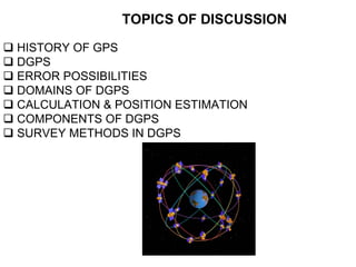
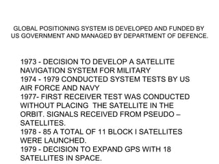
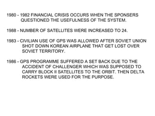
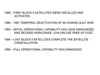
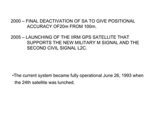
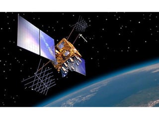
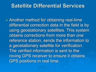
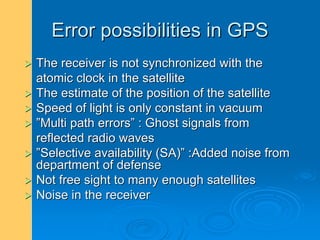
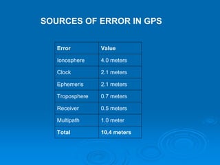
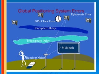
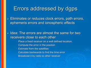
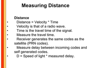
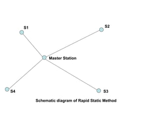
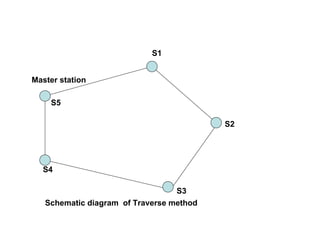
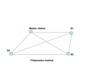
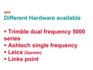
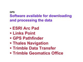
The document discusses the history and development of GPS and differential GPS (DGPS). It explains that DGPS uses a reference station at a known location to calculate errors in GPS positioning and apply corrections in real-time or post-processing to improve accuracy. The document outlines various DGPS systems, sources of GPS error, DGPS methods like rapid static and traverse, and components of GPS receivers.
It depicts the basic information about GPS technology and its various uses in engineering and other fields. May be useful for students of engineering and for presentation.
Differential Global Positioning System (DGPS) is an enhancement to Global Positioning System that provides improved location accuracy, from the
15-meter nominal GPS accuracy to about 10 cm in case of the best implementations. Differential Global Positioning System (DGPS) is a method of providing differential corrections to a Global Positioning System (GPS) receiver in order to improve the accuracy of the navigation solution. DGPS corrections originate from a reference station at a known location. The receivers in these reference stations can estimate errors in the GPS because, unlike the general population of GPS receivers, they have an accurate knowledge of their position.
DGPS uses a network of fixed, ground-based reference stations to broadcast the difference between the positions indicated by the GPS (satellite) systems and the known fixed positions. These stations broadcast the difference between the measured satellite pseudoranges and actual (internally computed) pseudoranges, and receiver stations may correct their pseudoranges by the same amount. The digital correction signal is typically broadcast locally over ground-based transmitters of shorter range.
A remote sensing system uses a detector to sense the reflected or emitted energy from the earth's surface, perhaps modified by the intervening atmosphere. The sensor can be on a satellite, aircraft, or drone. The sensor turns the energy into a voltage, which an analog to digital converter turns into a single integer value (called the Digital Number, or DN) for the energy. Alternatively a digital detector can store the DN directly. We can then display this value with an appropriate color to build up an image of the region sensed by the system. The DN represents the energy sensed by the sensor in a particular part of the electromagnetic spectrum, emitted or reflected from a particular region. The principles can also be applied to sonar imagery, especially useful in water where sound penetrates readily whereas electromagnetic energy attenuates rapidly.
Definitions,
Remote sensing systems can be active or passive: active systems put out their own source of energy (a large "flash bulb") whereas passive systems use solar energy reflected from the surface or thermal energy emitted by the surface. Active systems can achieve higher resolution.
Satellite resolution considers four things: spatial, spectral, radiometric, and temporal resolution.
Electromagnetic radiation and the atmosphere control many aspects of a remote sensing system.
Satellite orbits determine many characteristics of the imagery, what the satellite sees, and how often it revisits an area.
The signal to noise ratio is important for the design of remote sensing systems.
Satellite band tradeoffs.
Interpreting satellite reflectance patterns and images uses various statistical measures to assess surface properties in the image.
The colors used on the display are gray shading for single bands, and RGB for multi-band composites. We can also perform image merge and sharpening to combine the advantages of both panchromatic (higher spatial resolution) and color imagery (better differentiation of surface materials).
Keys for image analysis
Hyperspectral imagery
Spectral reflectance library--different materials reflect radiation differently
Remote Sensing Data Acquisition,Scanning/Imaging systemsdaniyal rustam
full of concepts about RS data acquisition scanning and imaging systems. Best for students of remote sensing. in this presentation we briefly explained the concept of scanning in remote sensing.
Jskkgkemgkdigieig
Re igkrkg
U
H
T
Rieogkskkfkfkeokdkdlwd
Feor. Eit eir r rid tnekt rb r r eir jekfkvkvind djcjejd bdicjebskjdbd skocck neb dkckcjcjjebd. Ksjsbd ekebenks d dndke. D dkdmm
The Global Positioning System (GPS), originally Navstar GPS,[1][2] is a space-based radionavigation system owned by the United States government and operated by the United States Air Force. It is a global navigation satellite system that provides geolocation and time information to a GPS receiver anywhere on or near the Earth where there is an unobstructed line of sight to four or more GPS satellites
Palestine last event orientationfvgnh .pptxRaedMohamed3
An EFL lesson about the current events in Palestine. It is intended to be for intermediate students who wish to increase their listening skills through a short lesson in power point.
Instructions for Submissions thorugh G- Classroom.pptxJheel Barad
This presentation provides a briefing on how to upload submissions and documents in Google Classroom. It was prepared as part of an orientation for new Sainik School in-service teacher trainees. As a training officer, my goal is to ensure that you are comfortable and proficient with this essential tool for managing assignments and fostering student engagement.
Biological screening of herbal drugs: Introduction and Need for
Phyto-Pharmacological Screening, New Strategies for evaluating
Natural Products, In vitro evaluation techniques for Antioxidants, Antimicrobial and Anticancer drugs. In vivo evaluation techniques
for Anti-inflammatory, Antiulcer, Anticancer, Wound healing, Antidiabetic, Hepatoprotective, Cardio protective, Diuretics and
Antifertility, Toxicity studies as per OECD guidelines
Read| The latest issue of The Challenger is here! We are thrilled to announce that our school paper has qualified for the NATIONAL SCHOOLS PRESS CONFERENCE (NSPC) 2024. Thank you for your unwavering support and trust. Dive into the stories that made us stand out!
Honest Reviews of Tim Han LMA Course Program.pptxtimhan337
Personal development courses are widely available today, with each one promising life-changing outcomes. Tim Han’s Life Mastery Achievers (LMA) Course has drawn a lot of interest. In addition to offering my frank assessment of Success Insider’s LMA Course, this piece examines the course’s effects via a variety of Tim Han LMA course reviews and Success Insider comments.
Synthetic Fiber Construction in lab .pptxPavel ( NSTU)
Synthetic fiber production is a fascinating and complex field that blends chemistry, engineering, and environmental science. By understanding these aspects, students can gain a comprehensive view of synthetic fiber production, its impact on society and the environment, and the potential for future innovations. Synthetic fibers play a crucial role in modern society, impacting various aspects of daily life, industry, and the environment. ynthetic fibers are integral to modern life, offering a range of benefits from cost-effectiveness and versatility to innovative applications and performance characteristics. While they pose environmental challenges, ongoing research and development aim to create more sustainable and eco-friendly alternatives. Understanding the importance of synthetic fibers helps in appreciating their role in the economy, industry, and daily life, while also emphasizing the need for sustainable practices and innovation.
Francesca Gottschalk - How can education support child empowerment.pptxEduSkills OECD
Francesca Gottschalk from the OECD’s Centre for Educational Research and Innovation presents at the Ask an Expert Webinar: How can education support child empowerment?
Embracing GenAI - A Strategic ImperativePeter Windle
Artificial Intelligence (AI) technologies such as Generative AI, Image Generators and Large Language Models have had a dramatic impact on teaching, learning and assessment over the past 18 months. The most immediate threat AI posed was to Academic Integrity with Higher Education Institutes (HEIs) focusing their efforts on combating the use of GenAI in assessment. Guidelines were developed for staff and students, policies put in place too. Innovative educators have forged paths in the use of Generative AI for teaching, learning and assessments leading to pockets of transformation springing up across HEIs, often with little or no top-down guidance, support or direction.
This Gasta posits a strategic approach to integrating AI into HEIs to prepare staff, students and the curriculum for an evolving world and workplace. We will highlight the advantages of working with these technologies beyond the realm of teaching, learning and assessment by considering prompt engineering skills, industry impact, curriculum changes, and the need for staff upskilling. In contrast, not engaging strategically with Generative AI poses risks, including falling behind peers, missed opportunities and failing to ensure our graduates remain employable. The rapid evolution of AI technologies necessitates a proactive and strategic approach if we are to remain relevant.
The Roman Empire A Historical Colossus.pdfkaushalkr1407
The Roman Empire, a vast and enduring power, stands as one of history's most remarkable civilizations, leaving an indelible imprint on the world. It emerged from the Roman Republic, transitioning into an imperial powerhouse under the leadership of Augustus Caesar in 27 BCE. This transformation marked the beginning of an era defined by unprecedented territorial expansion, architectural marvels, and profound cultural influence.
The empire's roots lie in the city of Rome, founded, according to legend, by Romulus in 753 BCE. Over centuries, Rome evolved from a small settlement to a formidable republic, characterized by a complex political system with elected officials and checks on power. However, internal strife, class conflicts, and military ambitions paved the way for the end of the Republic. Julius Caesar’s dictatorship and subsequent assassination in 44 BCE created a power vacuum, leading to a civil war. Octavian, later Augustus, emerged victorious, heralding the Roman Empire’s birth.
Under Augustus, the empire experienced the Pax Romana, a 200-year period of relative peace and stability. Augustus reformed the military, established efficient administrative systems, and initiated grand construction projects. The empire's borders expanded, encompassing territories from Britain to Egypt and from Spain to the Euphrates. Roman legions, renowned for their discipline and engineering prowess, secured and maintained these vast territories, building roads, fortifications, and cities that facilitated control and integration.
The Roman Empire’s society was hierarchical, with a rigid class system. At the top were the patricians, wealthy elites who held significant political power. Below them were the plebeians, free citizens with limited political influence, and the vast numbers of slaves who formed the backbone of the economy. The family unit was central, governed by the paterfamilias, the male head who held absolute authority.
Culturally, the Romans were eclectic, absorbing and adapting elements from the civilizations they encountered, particularly the Greeks. Roman art, literature, and philosophy reflected this synthesis, creating a rich cultural tapestry. Latin, the Roman language, became the lingua franca of the Western world, influencing numerous modern languages.
Roman architecture and engineering achievements were monumental. They perfected the arch, vault, and dome, constructing enduring structures like the Colosseum, Pantheon, and aqueducts. These engineering marvels not only showcased Roman ingenuity but also served practical purposes, from public entertainment to water supply.
1. GPS – Course 7
Differential GPS (DGPS)
SAJIKRISHNAN. K
Scientific Officer
NATMO
09 April 2012
2. TOPICS OF DISCUSSION
HISTORY OF GPS
DGPS
ERROR POSSIBILITIES
DOMAINS OF DGPS
CALCULATION & POSITION ESTIMATION
COMPONENTS OF DGPS
SURVEY METHODS IN DGPS
4. GLOBAL POSITIONING SYSTEM IS DEVELOPED AND FUNDED BY
US GOVERNMENT AND MANAGED BY DEPARTMENT OF DEFENCE.
1973 - DECISION TO DEVELOP A SATELLITE
NAVIGATION SYSTEM FOR MILITARY
1974 - 1979 CONDUCTED SYSTEM TESTS BY US
AIR FORCE AND NAVY
1977- FIRST RECEIVER TEST WAS CONDUCTED
WITHOUT PLACING THE SATELLITE IN THE
ORBIT. SIGNALS RECEIVED FROM PSEUDO –
SATELLITES.
1978 - 85 A TOTAL OF 11 BLOCK I SATELLITES
WERE LAUNCHED.
1979 - DECISION TO EXPAND GPS WITH 18
SATELLITES IN SPACE.
5. 1980 - 1982 FINANCIAL CRISIS OCCURS WHEN THE SPONSERS
QUESTIONED THE USEFULNESS OF THE SYSTEM.
1988 - NUMBER OF SATELLITES WERE INCREASED TO 24.
1983 - CIVILIAN USE OF GPS WAS ALLOWED AFTER SOVIET UNION
SHOT DOWN KOREAN AIRPLANE THAT GET LOST OVER
SOVIET TERRITORY.
1986 - GPS PROGRAMME SUFFERED A SET BACK DUE TO THE
ACCIDENT OF CHALLENGER WHICH WAS SUPPOSED TO
CARRY BLOCK II SATELLITES TO THE ORBIT. THEN DELTA
ROCKETS WERE USED FOR THE PURPOSE.
6. 1989 – FIRST BLOCK II SATELLITES WERE INSTALLED AND
ACTIVATED
1990 – 1991 TEMPORAL DEACTIVATION OF SA DURING GULF WAR
1993 – INITIAL OPERATIONAL CAPABILITY (IOC) WAS ANNOUNCED
AND DECIDED WORLDWIDE CIVILIAN USE FREE OF COST.
1994 – LAST BLOCK II SATELLITES COMPLETE THE SATELLITE
CONSTALLATION
1995 – FULL OPERATIONAL CAPABILITY WAS ANNONCED
7. 2000 – FINAL DEACTIVATION OF SA TO GIVE POSITIONAL
ACCURACY OF20m FROM 100m.
2005 – LAUNCHING OF THE IIRM GPS SATELLITE THAT
SUPPORTS THE NEW MILITARY M SIGNAL AND THE
SECOND CIVIL SIGNAL L2C.
•The current system became fully operational June 26, 1993 when
the 24th satellite was lunched.
8.
9. Control Stations
Schriever Air Force Base (formerly Falcon AFB) in Colorado.
Hawaii
Ascension Islands
Diego Gracia
Kwajalein
Newly added Control Stations after 2005
Washington DC
England
Equador
Argentinia
Bahrain
Australia
10.
11. What's the Differential?
Until 2000, civilian users had to contend
with Selective Availability (SA). The DoD
intentionally introduced random timing
errors in satellite signals to limit the
effectiveness of GPS and its potential
misuse by adversaries of the United
States. These timing errors could affect
the accuracy of readings by as much as
100 meters.
12. With SA removed, a single GPS
receiver from any manufacturer can
achieve accuracies of approximately 10
meters. To achieve the accuracies
needed for quality GIS records from one
to two meters up to a few centimeters
requires differential correction of the
data. The majority of data collected
using GPS for GIS is differentially
corrected to improve accuracy.
13. Differential GPS (DGPS) is a relatively
simple technique to improve positional
accuracy and integrity. This technique was
developed in the early 1980s, and it is
widely used in various forms.
14. DGPS is a method of improving the
accuracy of your receiver by adding
a local reference station to augment
the information available from the
satellites. It also improves the
integrity of the whole GPS system
by identifying certain errors.
15. •Differential GPS uses one unit at a
known location and a rover.
–The stationary unit compares its
calculated GPS location with the
actual location and computes the
error.
–The rover data is adjusted for the
error.
16. The underlying premise of differential GPS
(DGPS) is that any two receivers that are
relatively close together will experience similar
atmospheric errors.
DGPS requires that a GPS receiver be set up
on a precisely known location. This GPS
receiver is the base or reference station.
The base station receiver calculates its position
based on satellite signals and compares this
location to the known location.
17. The difference is applied to the GPS data recorded
by the second GPS receiver, which is known as
the roving receiver. The corrected information can
be applied to data from the roving receiver in real
time in the field using radio signals or through
post-processing after data capture using special
processing software.
18. Differential correction techniques are used to
enhance the quality of location data gathered
using global positioning system (GPS) receivers.
Differential correction can be applied in real-
time directly in the field or when post-processing
data in the office. Although both methods are
based on the same underlying principles, each
accesses different data sources and achieves
different levels of accuracy. Combining both
methods provides flexibility during data
collection and improves data integrity.
19. Real-Time DGPS
Real-time DGPS occurs when the base
station calculates and broadcasts
corrections for each satellite as it receives
the data. The correction is received by the
roving receiver via a radio signal
As a result, the position displayed and
logged to the data file of the roving GPS
receiver is a differentially corrected
position.
20. Satellite Differential Services
Another method for obtaining real-time
differential correction data in the field is by
using geostationary satellites. This system
obtains corrections from more than one
reference station, sends the information to
a geostationary satellite for verification.
The verified information is sent to the
roving GPS receiver to ensure it obtains
GPS positions in real time.
22. Error possibilities in GPS
The receiver is not synchronized with the
atomic clock in the satellite
The estimate of the position of the satellite
Speed of light is only constant in vacuum
”Multi path errors” : Ghost signals from
reflected radio waves
”Selective availability (SA)” :Added noise from
department of defense
Not free sight to many enough satellites
Noise in the receiver
23. SOURCES OF ERROR IN GPS
Error Value
Ionosphere 4.0 meters
Clock 2.1 meters
Ephemeris 2.1 meters
Troposphere 0.7 meters
Receiver 0.5 meters
Multipath 1.0 meter
Total 10.4 meters
26. Errors addressed by dgps
Eliminates or reduces clock errors, path errors,
ephemeris errors and ionospheric effects
Idea: The errors are almost the same for two
receivers close to each other
• Place a fixed receiver on a well defined location.
• Compute the error in the position
• Estimate from the satellites
• Calculate backwards to find the time error
• Broadcast it by radio to other receiver
27. Noise Error
Noise errors are the combined effect of code
noise (around 1 meter) and noise within the
receiver (around 1 meter).
28. BIAS ERROR
Selective Availability (SA)
SA is the intentional degradation of the SPS
signals by a time varying bias. SA is controlled by
the DOD to limit accuracy for non-U. S. military
and government users.
Selective availability is turned off.
Ephemeris data errors: 1 meter
Satellite orbits are constantly changing. Any error
in satellite position will result in an error for the
receiver position.
29. SV clock errors uncorrected by Control
Segment can result in one meter error.
Tropospheric delays: 1 meter.
The troposphere is the lower part
(ground level to from 8 to 13 km) of the
atmosphere that experiences the
changes in temperature, pressure, and
humidity associated with weather
changes.
Complex models of tropospheric delay
require estimates or measurements of
these parameters.
30. Bias Error--cont.
•Unmodeled ionosphere delays: 10 meters.
–The ionosphere is the layer of the atmosphere
from 50 to 500 km that consists of ionized air. The
transmitted model can only remove about half of
the possible 70 ns of delay leaving a ten meter un-
modeled residual.
•Multipath: 0.5 meters.
–Multipath is caused by reflected signals from
surfaces near the receiver that can either interfere
with or be mistaken for the signal that follows the
straight line path from the satellite.
31. Blunder
Blunders can result in errors of hundred of
kilometers.
Control segment mistakes due to computer or human
error can cause errors from one meter to hundreds of
kilometers.
User mistakes, including incorrect geodetic
datum selection, can cause errors from 1 to
hundreds of meters.
Receiver errors from software or hardware
failures can cause blunder errors of any size.
32. Differential GPS of USCG
Maritime Differential GPS (DGPS)
Managed by the U.S. Coast Guard (USCG)
Employs ground stations along the coasts
with known fixed locations.
Corrections are transmitted from ground
stations at low frequencies (200-500kHz).
Requires an additional Differential Beacon
Receiver (DBR) and an additional antenna.
Accuracy is a function of the distance from
the ground station.
33. WAAS
Wide Area Augmentation System (WAAS)
Managed by the FAA
Communicates with several ground stations.
Provides atmospheric corrections.
Early warning of GPS failures.
Same frequency as GPS
Higher data rate 250 Hz
Satellites are in geostationary orbits.
34.
35. Wide Area Augmentation System
Geostationary GPS Constellation
WAAS satellites
WAAS Control
Station (East
WAAS Control Local Area System (LAAS) Coast)
Station (West Coast)
36. Calculating a Position
• Measure distance to satellites.
• Obtain satellite positions.
• Perform triangulation calculations.
(Trilateration)
• Adjust local clock bias.
37. Measuring Distance
Distance
• Distance = Velocity * Time
• Velocity is that of a radio wave.
• Time is the travel time of the signal.
• Measure the travel time.
• Receiver generates the same codes as the
satellite (PRN codes).
• Measure delay between incoming codes and
self generated codes.
• D = Speed of light * measured delay.
38.
39. Obtain Satellite positions.
• Orbital data (Ephemeris) is embedded in
the satellite data message.
• Ephemeris data contains parameters that
describe the elliptical path of the satellite.
• Receiver uses this data to calculate the
position of the satellite. (X,Y,Z)
40. Perform triangulation calculations.
Triangulation in 2D
• If location of point A is known, and the
distance to point A is known, desired
position lies somewhere on a circle.
• Could be anywhere along circle A
41. Triangulation in 2D
• Distance to two points are known.
• Desired position is in one of two locations.
42. • Distance to three
points are known.
• Position is known!
45. • Calculating a Position Review
• Measure distance to satellites.
• Use pseudo ranges
• Obtain satellite positions.
• Decoded ephemeris from satellite message.
• Perform triangulation calculations.
• Need at least 3 satellites for triangulation.
• Adjust local clock bias to find position.
• Need 4th satellite to adjust bias.
51. DATA DISPLAY IN GPS
Once the GPS receiver has located its
position it is usually displayed in one of
two common formats:
– Latitude and longitude
– Universal transverse mercator (UTM).
52. LATITUDES AND LONGITUDES
Latitudes and longitudes are angles.
Both use the center of the earth as
the vertex, and both utilize the
equator, but they use a different
zero reference.
53. LATITUDE
Latitude gives the location of a place on the
Earth north or south of the Equator.
Latitude is an angular measurement in
degrees (marked with °) ranging from 0° at
the Equator to 90° at the poles (90° N for the
North Pole or 90° S for the South Pole)
The earth’s circumference is approximately 24,859.82
miles around the poles. So
Each degree of latitude ≈ 69 miles
55. Longitude
Longitude describes the location of a place
on earth east or west of a north-south line
called the Prime Meridian.
– Longitude is given as an angular measurement
ranging from 0° at the Prime Meridian to +180°
eastward and −180° westward.
– In 1884, the International Meridian Conference
adopted the Greenwich meridian as the
universal prime meridian or zero point of
longitude.
57. Longitude--cont.
The circumference of the
earth at the equator is
approximately 24,901.55
miles. So
Each degree of longitude ≈ 69 miles
A longitude of 134o west would be 9,246 west of the prime meridian.
58. Longitude--cont.
• There is an important
difference between
latitude and longitude.
• The circumference of the
earth declines as the
latitude increase away
from the equator.
• This means the miles per
degree of longitude
changes with the latitude.
• This makes determining
the distance between two
points identified by
longitude more difficult.
59. COMPONENTS OF DGPS
MASTER RECEIVER AND ROVERS
MASTER RECEIVER IS KEPT AT
KNOWN POINT.
RELATIVE POSITION OF ROVERS ARE
FIXED WITH RESPECT TO THE
MASTER RECEIVER
60. The main components of GPS
receivers are:
Antenna with pre-amplifier
Sensor to sense the data
Memory and display panel
Keyboard
Precision oscillator (clock)-quartz
Power supply – Ni-Cd - 12v battery
Computer with supporting software
for data download and processing.
61. Antenna detects the electromagnetic
waves arriving form satellite, converts the
wave energy into electric current, amplify
the signal strength and hands the signal
over to receive electronics.
Several antennas are available
Monopole or dipole
Helix
Spiral helix
Microstrip
Choke ring
62. S1 S2
Master Station
S4 S3
Schematic diagram of Rapid Static Method
66. GPS
Software available for downloading
and processing the data
ESRI Arc Pad
Links Point
GPS Pathfinder
Thales Navigation
Trimble Data Transfer
Trimble Geomatics Office