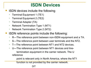
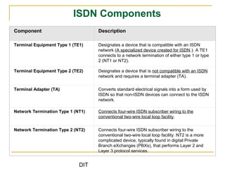
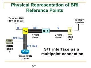
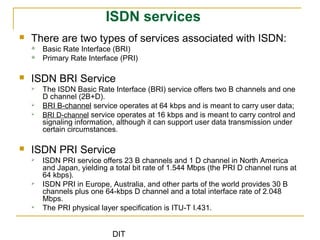
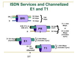
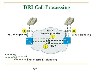
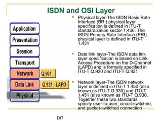
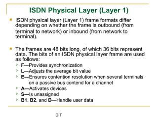
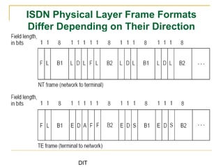
DIT
Dar es Salaam institute of Technology (DIT)
ETU 07420
Switching Systems
Ally, J
jumannea@gmail.com
DIT
Integrated Service Digital Network
(ISDN)
DIT
Integrated Service Digital Network (ISDN)
introduction
 ISDN refers to a set of communication protocols
proposed by telephone companies to permit telephone
networks to carry data, voice, and other source material
 ISDN provides a set of digital services that concurrently
deliver voice, data, text, graphics, music, videos, and
information to end users
 ISDN is comprised of digital telephony and data
transport services offered by regional telephone carriers.
 ISDN is generally viewed as an alternative to frame relay
and T1 wide area telephone services (WATS)
DIT
What is ISDN
 ISDN is a set of standard that defines an end-to-end
digital network
 The ISDN standards define the hardware and call setup
schemes for end-to-end digital connectivity
 Digital connectivity via ISDN to the local site has many
benefits include:
 Carries many types of network traffic like data, voice, and videos,
etc
 Much faster call setup using out-of-band (D channel) signaling
than modem connections
 Much faster data transfer rate using bearer (B channel) services
at 64Kbps per channel
DIT
The advantages of ISDN
 The advantages of ISDN over analog
connections include:
 Higher speed
 Faster call setup
 Cheaper than leased lines
 Voice and data can be run simultaneously
DIT
ISDN Devices
 ISDN devices include the following
 Terminal Equipment 1 (TE1)
 Terminal Equipment 2 (TE2)
 Terminal Adapter (TA)
 Network Termination Type 1 (NT1)
 Network Termination Type 2 (NT2)
 ISDN reference points include the following:
 R—The reference point between non-ISDN equipment and a TA.
 S—The reference point between user terminals and the NT2.
 T—The reference point between NT1 and NT2 devices.
 U—The reference point between NT1 devices and line-
termination equipment in the carrier network. The U
reference
point is relevant only in North America, where the NT1
function is not provided by the carrier network.
DIT
ISDN Configuration Between Devices and
Reference Points
DIT
ISDN Components
Component Description
Terminal Equipment Type 1 (TE1) Designates a device that is compatible with an ISDN
network (A specialized device created for ISDN.). A TE1
connects to a network termination of either type 1 or type
2 (NT1 or NT2).
Terminal Equipment Type 2 (TE2) Designates a device that is not compatible with an ISDN
network and requires a terminal adapter (TA).
Terminal Adapter (TA) Converts standard electrical signals into a form used by
ISDN so that non-ISDN devices can connect to the ISDN
network.
Network Termination Type 1 (NT1) Connects four-wire ISDN subscriber wiring to the
conventional two-wire local loop facility.
Network Termination Type 2 (NT2) Connects four-wire ISDN subscriber wiring to the
conventional two-wire local loop facility. NT2 is a more
complicated device, typically found in digital Private
Branch eXchanges (PBXs), that performs Layer 2 and
Layer 3 protocol services.
DIT
Physical Representation of BRI
Reference Points
Cisco ISDN
router
To ISDN
service
Wall
jack
4-wire
circuit
2-wire
circuit
S/T U
TA NT1NT1
S/T bus
S/T bus
S/T interface as a
multipoint connection
To non-ISDN
device (TE2)
R
ISDN
phon
e
DIT
ISDN services
 There are two types of services associated with ISDN:
 Basic Rate Interface (BRI)
 Primary Rate Interface (PRI)
 ISDN BRI Service
 The ISDN Basic Rate Interface (BRI) service offers two B channels and one
D channel (2B+D).
 BRI B-channel service operates at 64 kbps and is meant to carry user data;
 BRI D-channel service operates at 16 kbps and is meant to carry control and
signaling information, although it can support user data transmission under
certain circumstances.
 ISDN PRI Service
 ISDN PRI service offers 23 B channels and 1 D channel in North America
and Japan, yielding a total bit rate of 1.544 Mbps (the PRI D channel runs at
64 kbps).
 ISDN PRI in Europe, Australia, and other parts of the world provides 30 B
channels plus one 64-kbps D channel and a total interface rate of 2.048
Mbps.
 The PRI physical layer specification is ITU-T I.431.
DIT
ISDN Services and Channelized
E1 and T1
64 kbps
64 kbps
16 kbps
144
kbps
2B
D }{
BRI
T1 1.544
Mbps
or
E1 2.048
Mbps
(includes
sync)
23B (T1) or
30B (E1)
D
64 kbps
each
64 kbps}PR
I
2.048 Mbps
(includes sync)
31 64 kbps
channels }E1
1.544 Mbps
(includes sync)
24 64
kbps
channel
s
}T1
DIT
31
BRI Call Processing
ISDN
service provider
4
B
channelD channel/SS7 signaling
2 SS7
Q.931 signaling Q.931 signaling
DIT
ISDN and OSI Layer
 Physical layer-The ISDN Basic Rate
Interface (BRI) physical layer
specification is defined in ITU-T
standardization sector 1.430. The
ISDN Primary Rate Interface (PRI)
physical layer is defined in ITU-T
1.431
 Data link layer-The ISDN data link
layer specification is based on Link
Access Procedure on the D-Channel
(LAPD) and is formally specified in
ITU-T Q.920 and ITU-T Q.921
 Network layer-The ISDN network
layer is defined in ITU-T 1.450 (also
known as ITU-T Q.930) and ITU-T
1.451 (also known as ITU-T Q.930.
Together these two standards
specify user-to-user, circuit-switched,
and packet-switched connection
DIT
ISDN Physical Layer (Layer 1)
 ISDN physical layer (Layer 1) frame formats differ
depending on whether the frame is outbound (from
terminal to network) or inbound (from network to
terminal).
 The frames are 48 bits long, of which 36 bits represent
data. The bits of an ISDN physical layer frame are used
as follows:
 F—Provides synchronization
 L—Adjusts the average bit value
 E—Ensures contention resolution when several terminals
on a passive bus contend for a channel
 A—Activates devices
 S—Is unassigned
 B1, B2, and D—Handle user data
DIT
ISDN Physical Layer Frame Formats
Differ Depending on Their Direction
DIT
ISDN Physical Layer operation
 Multiple ISDN user devices can be physically attached to one circuit. In
this configuration, collisions can result if two terminals transmit
simultaneously.
 Therefore, ISDN provides features to determine link contention. When
an NT receives a D bit from the TE, it echoes back the bit in the next E-
bit position. The TE expects the next E bit to be the same as its last
transmitted D bit.
 Terminals cannot transmit into the D channel unless they first detect a
specific number of ones (indicating “no signal”) corresponding to a pre-
established priority. If the TE detects a bit in the echo (E) channel that
is different from its D bits, it must stop transmitting immediately.
 After successful D-message transmission, the terminal has its priority
reduced by requiring it to detect more continuous ones before
transmitting.
 Terminals cannot raise their priority until all other devices on the same
line have had an opportunity to send a D message.
DIT
IDSN Data Link Layer (Layer 2)
 Layer 2 of the ISDN signaling protocol is Link Access Procedure, D
channel (LAPD). LAPD is similar to High-Level Data Link Control
(HDLC) and Link Access Procedure, Balanced (LAPB).
 As the expansion of the LAPD acronym indicates, this layer is used
across the D channel to ensure that control and signaling information
flows and is received properly.
DIT
ISDN Network Layer (Layer 3)
 Two Layer 3 specifications are used for ISDN
signaling: ITU-T I.450 (also known as ITU-T
Q.930) and ITU-T I.451 (also known as ITU-T
Q.931).
 Together, these protocols support user-to-user,
circuit-switched, and packet-switched
connections.
 A variety of call-establishment, call-termination,
information, and miscellaneous messages are
specified, including SETUP, CONNECT,
RELEASE, USER INFORMATION, CANCEL,
STATUS, and DISCONNECT.
DIT
Typical stages of an ISDN circuit-switched
call
DIT
Thanks!
Technology changes but communication lasts.

Switching systems lecture5

  • 1.
    DIT Dar es Salaaminstitute of Technology (DIT) ETU 07420 Switching Systems Ally, J jumannea@gmail.com
  • 2.
  • 3.
    DIT Integrated Service DigitalNetwork (ISDN) introduction  ISDN refers to a set of communication protocols proposed by telephone companies to permit telephone networks to carry data, voice, and other source material  ISDN provides a set of digital services that concurrently deliver voice, data, text, graphics, music, videos, and information to end users  ISDN is comprised of digital telephony and data transport services offered by regional telephone carriers.  ISDN is generally viewed as an alternative to frame relay and T1 wide area telephone services (WATS)
  • 4.
    DIT What is ISDN ISDN is a set of standard that defines an end-to-end digital network  The ISDN standards define the hardware and call setup schemes for end-to-end digital connectivity  Digital connectivity via ISDN to the local site has many benefits include:  Carries many types of network traffic like data, voice, and videos, etc  Much faster call setup using out-of-band (D channel) signaling than modem connections  Much faster data transfer rate using bearer (B channel) services at 64Kbps per channel
  • 5.
    DIT The advantages ofISDN  The advantages of ISDN over analog connections include:  Higher speed  Faster call setup  Cheaper than leased lines  Voice and data can be run simultaneously
  • 6.
    DIT ISDN Devices  ISDNdevices include the following  Terminal Equipment 1 (TE1)  Terminal Equipment 2 (TE2)  Terminal Adapter (TA)  Network Termination Type 1 (NT1)  Network Termination Type 2 (NT2)  ISDN reference points include the following:  R—The reference point between non-ISDN equipment and a TA.  S—The reference point between user terminals and the NT2.  T—The reference point between NT1 and NT2 devices.  U—The reference point between NT1 devices and line- termination equipment in the carrier network. The U reference point is relevant only in North America, where the NT1 function is not provided by the carrier network.
  • 7.
    DIT ISDN Configuration BetweenDevices and Reference Points
  • 8.
    DIT ISDN Components Component Description TerminalEquipment Type 1 (TE1) Designates a device that is compatible with an ISDN network (A specialized device created for ISDN.). A TE1 connects to a network termination of either type 1 or type 2 (NT1 or NT2). Terminal Equipment Type 2 (TE2) Designates a device that is not compatible with an ISDN network and requires a terminal adapter (TA). Terminal Adapter (TA) Converts standard electrical signals into a form used by ISDN so that non-ISDN devices can connect to the ISDN network. Network Termination Type 1 (NT1) Connects four-wire ISDN subscriber wiring to the conventional two-wire local loop facility. Network Termination Type 2 (NT2) Connects four-wire ISDN subscriber wiring to the conventional two-wire local loop facility. NT2 is a more complicated device, typically found in digital Private Branch eXchanges (PBXs), that performs Layer 2 and Layer 3 protocol services.
  • 9.
    DIT Physical Representation ofBRI Reference Points Cisco ISDN router To ISDN service Wall jack 4-wire circuit 2-wire circuit S/T U TA NT1NT1 S/T bus S/T bus S/T interface as a multipoint connection To non-ISDN device (TE2) R ISDN phon e
  • 10.
    DIT ISDN services  Thereare two types of services associated with ISDN:  Basic Rate Interface (BRI)  Primary Rate Interface (PRI)  ISDN BRI Service  The ISDN Basic Rate Interface (BRI) service offers two B channels and one D channel (2B+D).  BRI B-channel service operates at 64 kbps and is meant to carry user data;  BRI D-channel service operates at 16 kbps and is meant to carry control and signaling information, although it can support user data transmission under certain circumstances.  ISDN PRI Service  ISDN PRI service offers 23 B channels and 1 D channel in North America and Japan, yielding a total bit rate of 1.544 Mbps (the PRI D channel runs at 64 kbps).  ISDN PRI in Europe, Australia, and other parts of the world provides 30 B channels plus one 64-kbps D channel and a total interface rate of 2.048 Mbps.  The PRI physical layer specification is ITU-T I.431.
  • 11.
    DIT ISDN Services andChannelized E1 and T1 64 kbps 64 kbps 16 kbps 144 kbps 2B D }{ BRI T1 1.544 Mbps or E1 2.048 Mbps (includes sync) 23B (T1) or 30B (E1) D 64 kbps each 64 kbps}PR I 2.048 Mbps (includes sync) 31 64 kbps channels }E1 1.544 Mbps (includes sync) 24 64 kbps channel s }T1
  • 12.
    DIT 31 BRI Call Processing ISDN serviceprovider 4 B channelD channel/SS7 signaling 2 SS7 Q.931 signaling Q.931 signaling
  • 13.
    DIT ISDN and OSILayer  Physical layer-The ISDN Basic Rate Interface (BRI) physical layer specification is defined in ITU-T standardization sector 1.430. The ISDN Primary Rate Interface (PRI) physical layer is defined in ITU-T 1.431  Data link layer-The ISDN data link layer specification is based on Link Access Procedure on the D-Channel (LAPD) and is formally specified in ITU-T Q.920 and ITU-T Q.921  Network layer-The ISDN network layer is defined in ITU-T 1.450 (also known as ITU-T Q.930) and ITU-T 1.451 (also known as ITU-T Q.930. Together these two standards specify user-to-user, circuit-switched, and packet-switched connection
  • 14.
    DIT ISDN Physical Layer(Layer 1)  ISDN physical layer (Layer 1) frame formats differ depending on whether the frame is outbound (from terminal to network) or inbound (from network to terminal).  The frames are 48 bits long, of which 36 bits represent data. The bits of an ISDN physical layer frame are used as follows:  F—Provides synchronization  L—Adjusts the average bit value  E—Ensures contention resolution when several terminals on a passive bus contend for a channel  A—Activates devices  S—Is unassigned  B1, B2, and D—Handle user data
  • 15.
    DIT ISDN Physical LayerFrame Formats Differ Depending on Their Direction
  • 16.
    DIT ISDN Physical Layeroperation  Multiple ISDN user devices can be physically attached to one circuit. In this configuration, collisions can result if two terminals transmit simultaneously.  Therefore, ISDN provides features to determine link contention. When an NT receives a D bit from the TE, it echoes back the bit in the next E- bit position. The TE expects the next E bit to be the same as its last transmitted D bit.  Terminals cannot transmit into the D channel unless they first detect a specific number of ones (indicating “no signal”) corresponding to a pre- established priority. If the TE detects a bit in the echo (E) channel that is different from its D bits, it must stop transmitting immediately.  After successful D-message transmission, the terminal has its priority reduced by requiring it to detect more continuous ones before transmitting.  Terminals cannot raise their priority until all other devices on the same line have had an opportunity to send a D message.
  • 17.
    DIT IDSN Data LinkLayer (Layer 2)  Layer 2 of the ISDN signaling protocol is Link Access Procedure, D channel (LAPD). LAPD is similar to High-Level Data Link Control (HDLC) and Link Access Procedure, Balanced (LAPB).  As the expansion of the LAPD acronym indicates, this layer is used across the D channel to ensure that control and signaling information flows and is received properly.
  • 18.
    DIT ISDN Network Layer(Layer 3)  Two Layer 3 specifications are used for ISDN signaling: ITU-T I.450 (also known as ITU-T Q.930) and ITU-T I.451 (also known as ITU-T Q.931).  Together, these protocols support user-to-user, circuit-switched, and packet-switched connections.  A variety of call-establishment, call-termination, information, and miscellaneous messages are specified, including SETUP, CONNECT, RELEASE, USER INFORMATION, CANCEL, STATUS, and DISCONNECT.
  • 19.
    DIT Typical stages ofan ISDN circuit-switched call
  • 20.

Editor's Notes

  • #7 Purpose: The figure shows the vision of ISDN as a network that allows voice, data, video, and special services to use the same facilities. Emphasize: ISDN allows the usage of existing telephone cables (in most cases) for high-speed data as well as voice. Transition: The next figure shows the ISDN services.
  • #11 Purpose: This figure assigns well-known devices to the abstract reference points and functional groups. Emphasize: The Network Termination 1 (NT1) is part of the customer premises equipment (CPE) equipment in the U.S. and is part of the central office (CO) equipment in Europe. Cisco routers for small offices, (700, 800, 1600, and 1700 series) come with or without internal NT1 devices. Transition: The next figure shows ISDN PRI reference points.
  • #13 Purpose: This figure compares the physical characteristics of ISDN BRI and PRI. Emphasize: Compare the number of channels in BRI and PRI. Transition: The next figure shows the sequence of a BRI call.
  • #14 Purpose: This figure shows the sequence of events and the usage of the B and D channel in the establishment of a BRI call. Emphasize: Normally, the D channel is only used for signaling/call control. Q.931 signaling is between the end user and the local ISDN switch. In the provider network, Signaling System 7 (SS7) is used for call control between the switches. Note: The D channel can be used for low-speed data. Specifically, X.25 can be configured to run over the D channel if the ISDN service provider can provide the service. Transition: The next figure shows the BRI functional groups and reference points.
  • #18 -Multiple ISDN user devices can be physically attached to one circuit. In this configuration, collisions can result if two terminals transmit simultaneously. Therefore, ISDN provides features to determine link contention. When an NT receives a D bit from the TE, it echoes back the bit in the next E-bit position. The TE expects the next E bit to be the same as its last transmitted D bit. -Terminals cannot transmit into the D channel unless they first detect a specific number of ones (indicating “no signal”) corresponding to a pre-established priority. If the TE detects a bit in the echo (E) channel that is different from its D bits, it must stop transmitting immediately. This simple technique ensures that only one terminal can transmit its D message at one time. After successful D-message transmission, the terminal has its priority reduced by requiring it to detect more continuous ones before transmitting. Terminals cannot raise their priority until all other devices on the same line have had an opportunity to send a D message. Telephone connections have higher priority than all other services, and signaling information has a higher priority than non-signaling information.
  • #19 -Layer 2 of the ISDN signaling protocol is Link Access Procedure, D channel (LAPD). LAPD is similar to High-Level Data Link Control (HDLC) and Link Access Procedure, Balanced (LAPB) (see Chapter 16, “Synchronous Data Link Control and Derivatives,” and Chapter 17, “X.25,” for more information on these protocols). As the expansion of the LAPD acronym indicates, this layer is used across the D channel to ensure that control and signaling information flows and is received properly. The LAPD frame format (see Figure 12-3) is very similar to that of HDLC; like HDLC, LAPD uses supervisory, information, and unnumbered frames. The LAPD protocol is formally specified in ITU-T Q.920 and ITU-T Q.921. -The LAPD Flag and Control fields are identical to those of HDLC. The LAPD Address field can be either 1 or 2 bytes long. If the extended address bit of the first byte is set, the address is 1 byte; if it is not set, the address is 2 bytes. The first Address-field byte contains the service access point identifier (SAPI), which identifies the portal at which LAPD services are provided to Layer 3. The C/R bit indicates whether the frame contains a command or a response. The Terminal Endpoint Identifier (TEI) field identifies either a single terminal or multiple terminals. A TEI of all ones indicates a broadcast.
  • #20 Two Layer 3 specifications are used for ISDN signaling: ITU-T (formerly CCITT) I.450 (also known as ITU-T Q.930) and ITU-T I.451 (also known as ITU-T Q.931). Together, these protocols support user-to-user, circuit-switched, and packet-switched connections. A variety of call-establishment, call-termination, information, and miscellaneous messages are specified, including SETUP, CONNECT, RELEASE, USER INFORMATION, CANCEL, STATUS, and DISCONNECT. These messages are functionally similar to those provided by the X.25 protocol (see Chapter 17 for more information). Figure 12-4, from ITU-T I.451, shows the typical stages of an ISDN circuit-switched call.