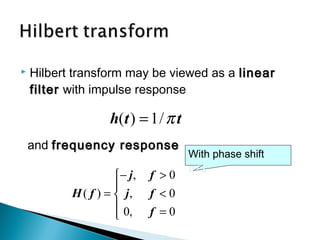
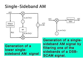
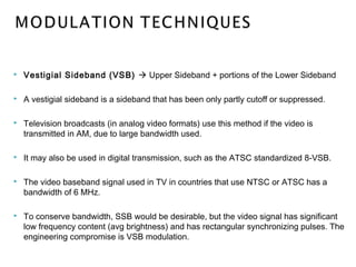
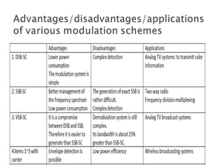
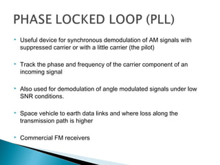
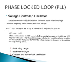
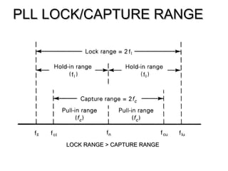
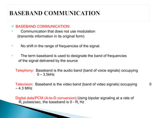
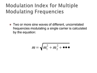
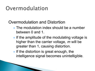
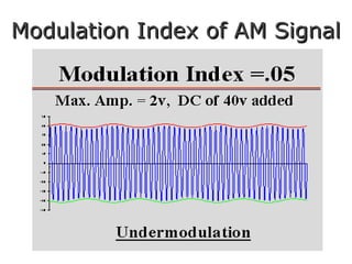
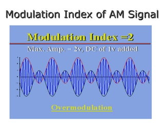
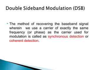
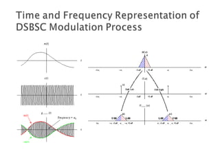
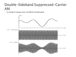
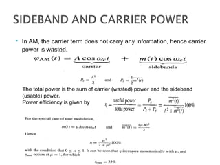
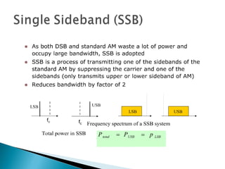
The document discusses baseband and modulated communication signals. It defines baseband signals as those that do not use modulation and transmit information in its original form within the baseband frequency range. Modulated signals use carrier waves to shift the information signal to higher frequencies suitable for transmission. The key types of modulation discussed are amplitude modulation (AM), which varies the amplitude of the carrier wave, and angle modulation including frequency modulation (FM) and phase modulation (PM), which vary the frequency or phase of the carrier. Common applications of baseband signals include telephony and digital data transmission over copper wires, while modulated signals are required for wireless transmission through free space using radio frequencies.

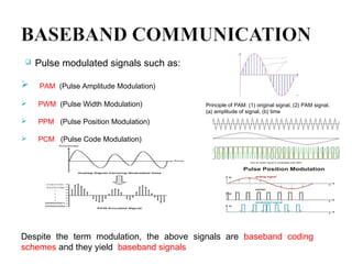
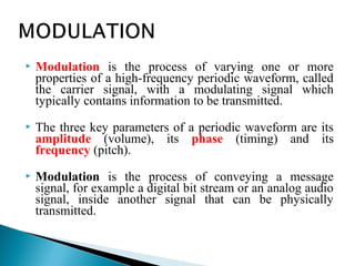
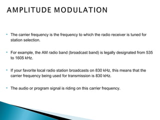
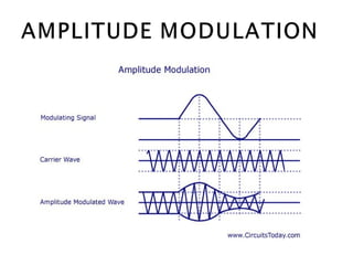
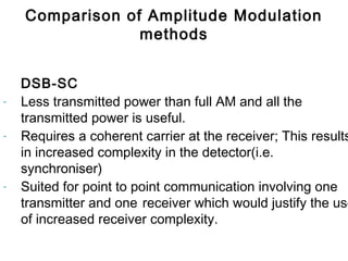
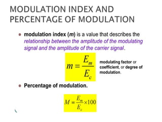
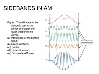
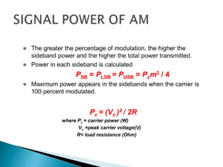
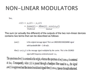
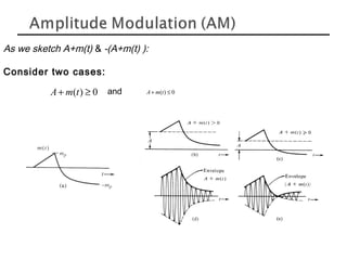
![ The amplitude of high-carrier signal is varied
according to the instantaneous amplitude of the
modulating message signal m(t).
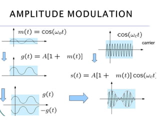
Carrier Signal: or
Modulating Message Signal: or
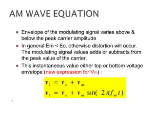
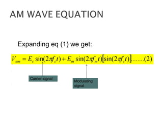
The AM Signal:
cos(2 ) cos( )
( ) : cos(2 ) cos( )
( ) [ ( )]cos(2 )
c c
m m
AM c c
f t t
m t f t t
s t A m t f t
π ω
π ω
π= +](https://image.slidesharecdn.com/2109986635316076040095000-150719033702-lva1-app6891/85/2109986-635316076040095000-19-320.jpg)
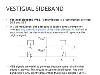
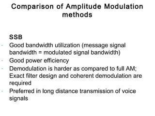
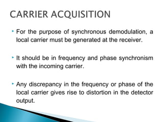
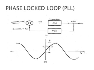
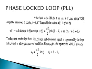
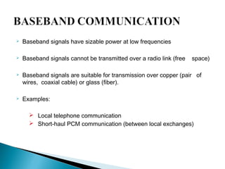
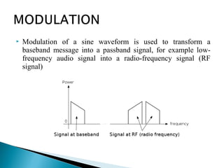
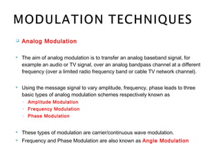
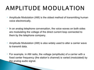
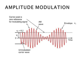
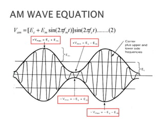
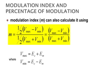
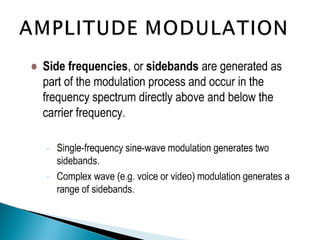
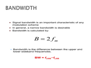
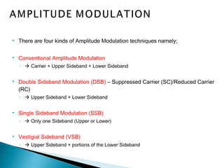
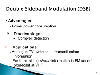
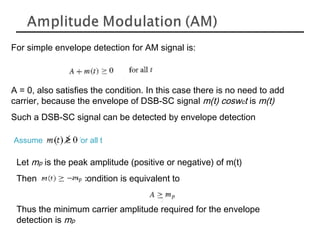
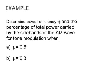
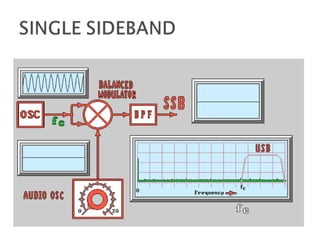
![ Mathematical expression for AM: time domain
expanding this produces:
In the frequency domain this gives:
( ) (1 cos ) cosAM m cS t k t tω ω= +
( ) cos cos cosc cAM mS t t k t tω ω ω= +
[ ])cos()cos(coscos:using 2
1 BABABA ++−=
2 2( ) cos cos( ) cos( )c c c
k k
AM m mS t t t tω ω ω ω ω= + − + +
frequency
k/2
k/2
Carrier, A=1.
upper sideband
lower
sideband
Amplitude
fcfc-fm fc+fm](https://image.slidesharecdn.com/2109986635316076040095000-150719033702-lva1-app6891/85/2109986-635316076040095000-20-320.jpg)
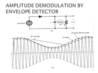
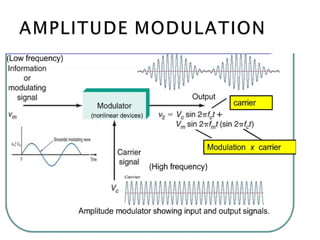
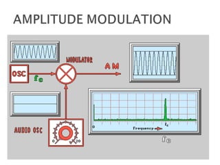
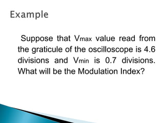
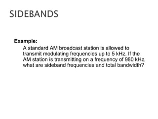
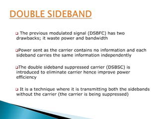
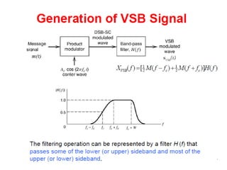
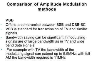
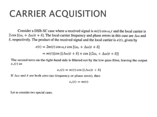
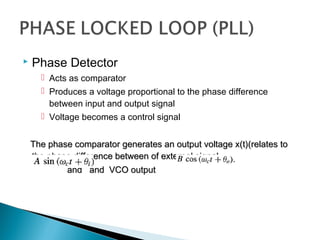
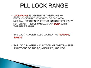
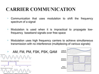
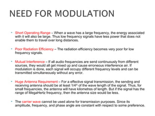
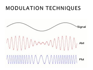
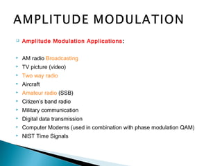
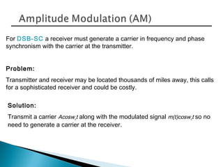
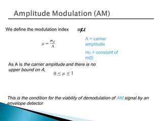
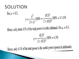
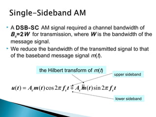
![Modulation
• This type of modulation shifts the spectrum of m(t) to the carrier frequency.
If
)()( wMtm ⇔
[ ])()(
2
1
cos)( ccc wwMwwMtwtm −++⇔](https://image.slidesharecdn.com/2109986635316076040095000-150719033702-lva1-app6891/85/2109986-635316076040095000-52-320.jpg)
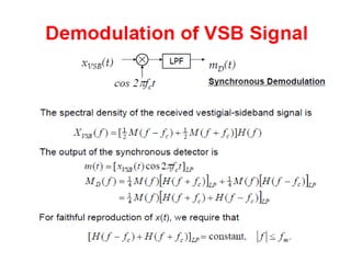
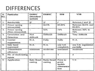
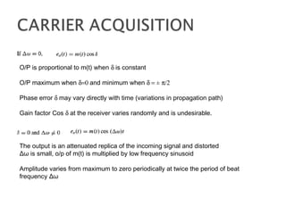
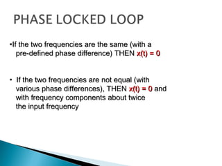
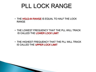
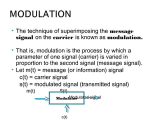
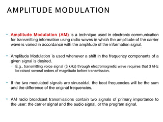
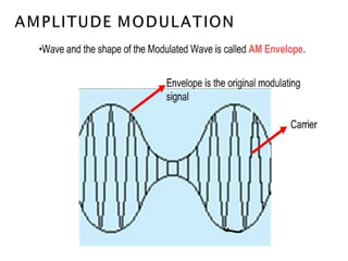
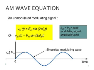
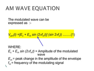
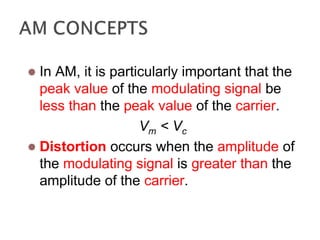
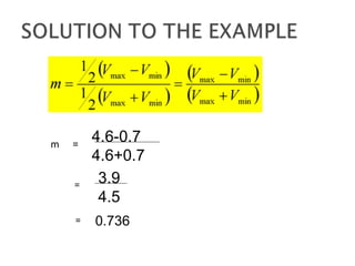
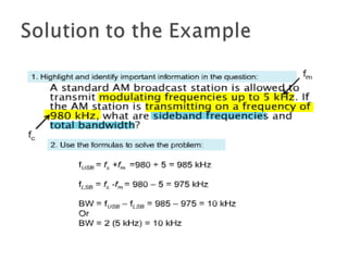
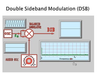
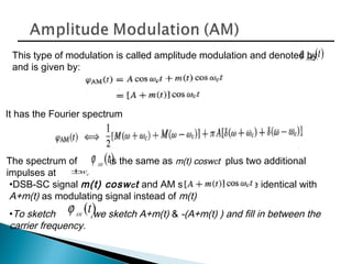
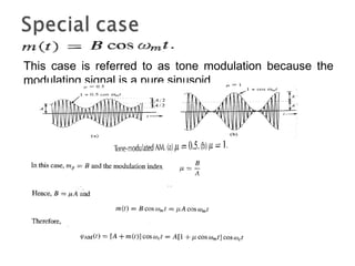
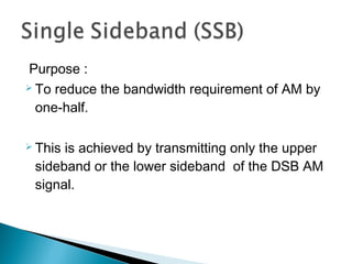
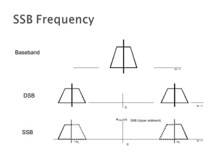
![53
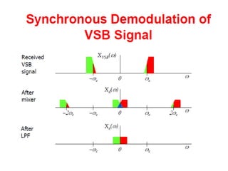
Demodulation
• The process of receiving the original signal from the modulated signal is
called demodulation.
• Demodulation is similar to modulation and can be performed by
multiplying the modulated signal again with the carrier signal
[ ])2cos()()(
2
12cos)()( t
c
wtmtmt
c
wtmte +==
[ ])2()2(
4
1)(
2
1)( cc
wwMwwMwMwE −+++=](https://image.slidesharecdn.com/2109986635316076040095000-150719033702-lva1-app6891/85/2109986-635316076040095000-53-320.jpg)
![• MESSAGE SIGNAL =
• CARRIER SIGNAL =
• MODULATED SIGNAL =
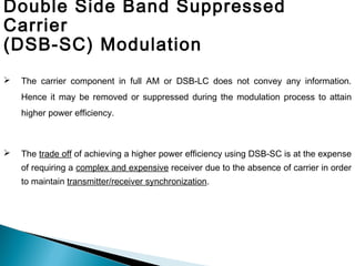
DOUBLE SIDEBAND MODULATION SUPPRESSED CARRIER (DSB-SC)
)(cos)( ωω MtEtm mm ↔=
)(cos)( ωω CtEtC cc ↔=
ttEEtCtm cmcm ωω coscos)()( =
[ ]tt
EE
mcmc
cm
)cos()cos(
2
ωωωω −++
[ ])()(
2
cos)( mcmc
cm
c MM
EE
ttm ωωωωω −++↔
fπω 2= )cos(
2
1
)cos(
2
1
))(cos(cos YXYXYX −++=](https://image.slidesharecdn.com/2109986635316076040095000-150719033702-lva1-app6891/85/2109986-635316076040095000-55-320.jpg)
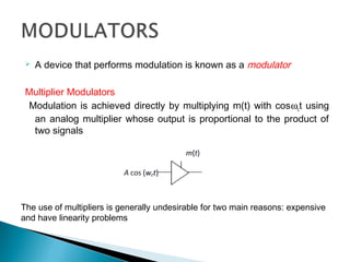
![DOUBLE SIDEBAND MODULATION SUPPRESSED CARRIER (DSB-SC)
ttm mωcos)( =
ttC cωcos)( =
)()( tCtm
[ ]tt
EE
mcmc
cm
)cos()cos(
2
ωωωω −++
MULTIPLIER
MODULATOR](https://image.slidesharecdn.com/2109986635316076040095000-150719033702-lva1-app6891/85/2109986-635316076040095000-56-320.jpg)
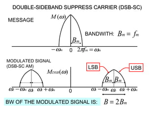
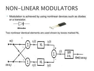
![DOUBLE-SIDEBAND SUPPRESS CARRIER (DSB-SC)DOUBLE-SIDEBAND SUPPRESS CARRIER (DSB-SC)
THE MODULATED CARRIER SPECTRUM CENTERED
AT fc IS COMPOSED OF AN UPPER SIDEBAND ABOVE
fc, (USB), AND A LOWER SIDEBAND BELOW fc, (LSB).
USBLSB
2 fm
[ ]tt
EE
mcmc
cm
)cos()cos(
2
ωωωω −++
MODULATED SIGNAL DOES NOT HAVE A COMPONENT AT fc, IN
THIS CASE THE SCHEME IS CALLED DSB-SC MODULATION](https://image.slidesharecdn.com/2109986635316076040095000-150719033702-lva1-app6891/85/2109986-635316076040095000-60-320.jpg)
![HL(t)=1/2[sgn(f+fc)-sgn(f-fc)]
XDSB(f)=1/2AC[M(f+fc)+M(f-fc)]
XSSB(f)=1/4AC[M(f+fc) sgn(f+fc)]+M(f-fc)sgn(f+fc)]-
1/4AC[M(f+fc) sgn(f-fc) +[M(f-fc) sgn(f-fc)]
= 1/4AC[M(f+fc)+M(f-fc)]+ 1/4AC[M(f+fc) sgn(f+fc)]-
M(f-fc)sgn(f-fc)]
=1/2AC m(t)cosωct 1/4[M(f+fc)+M(f-fc)]](https://image.slidesharecdn.com/2109986635316076040095000-150719033702-lva1-app6891/85/2109986-635316076040095000-81-320.jpg)
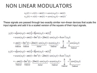
![Hilbert Transform
(t) -jsgnf M(f)
m(t)e±j2Πfct
M(f fc)
m(t)e±2Πfct
-j M(f fc)sgn(f fc)
j-1
{1/4AC[M(f+fc)sgn(f+fc)]-M(f-fc)sgn(f-fc)]}
=-AC1/4j (t) e-j2Πfct
+ AC1/4j (t) e2Πfct
=1/2Acb (t)sin2Πfct
XSSB(f)=1/2AC m(t)cosωct+ 1/2Ac (t)sinωct](https://image.slidesharecdn.com/2109986635316076040095000-150719033702-lva1-app6891/85/2109986-635316076040095000-82-320.jpg)