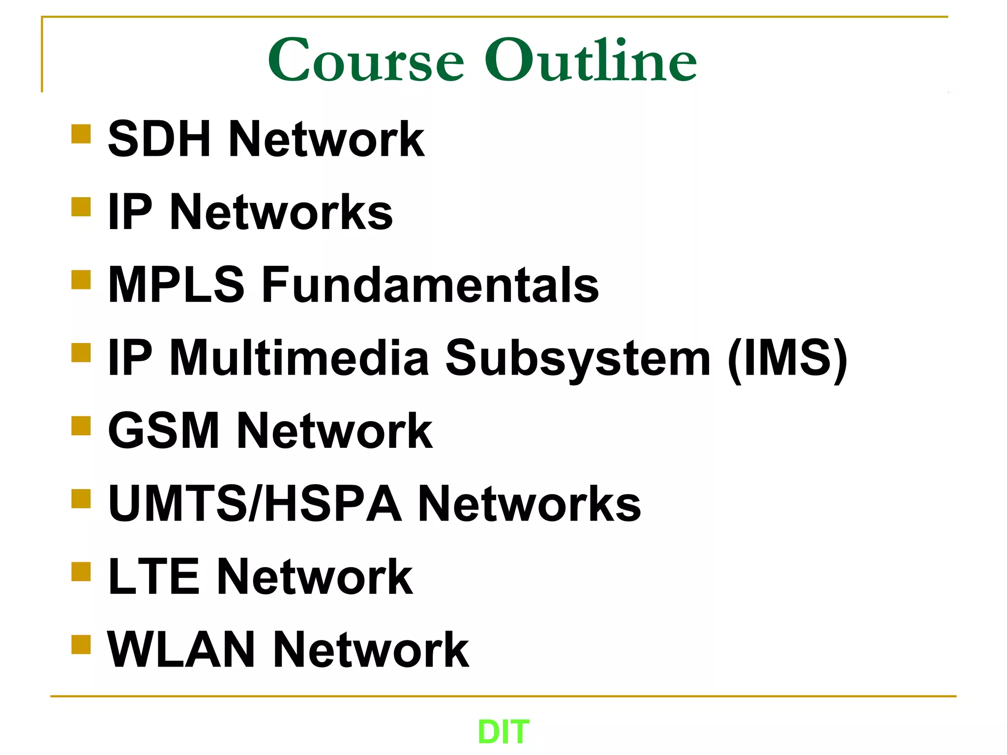
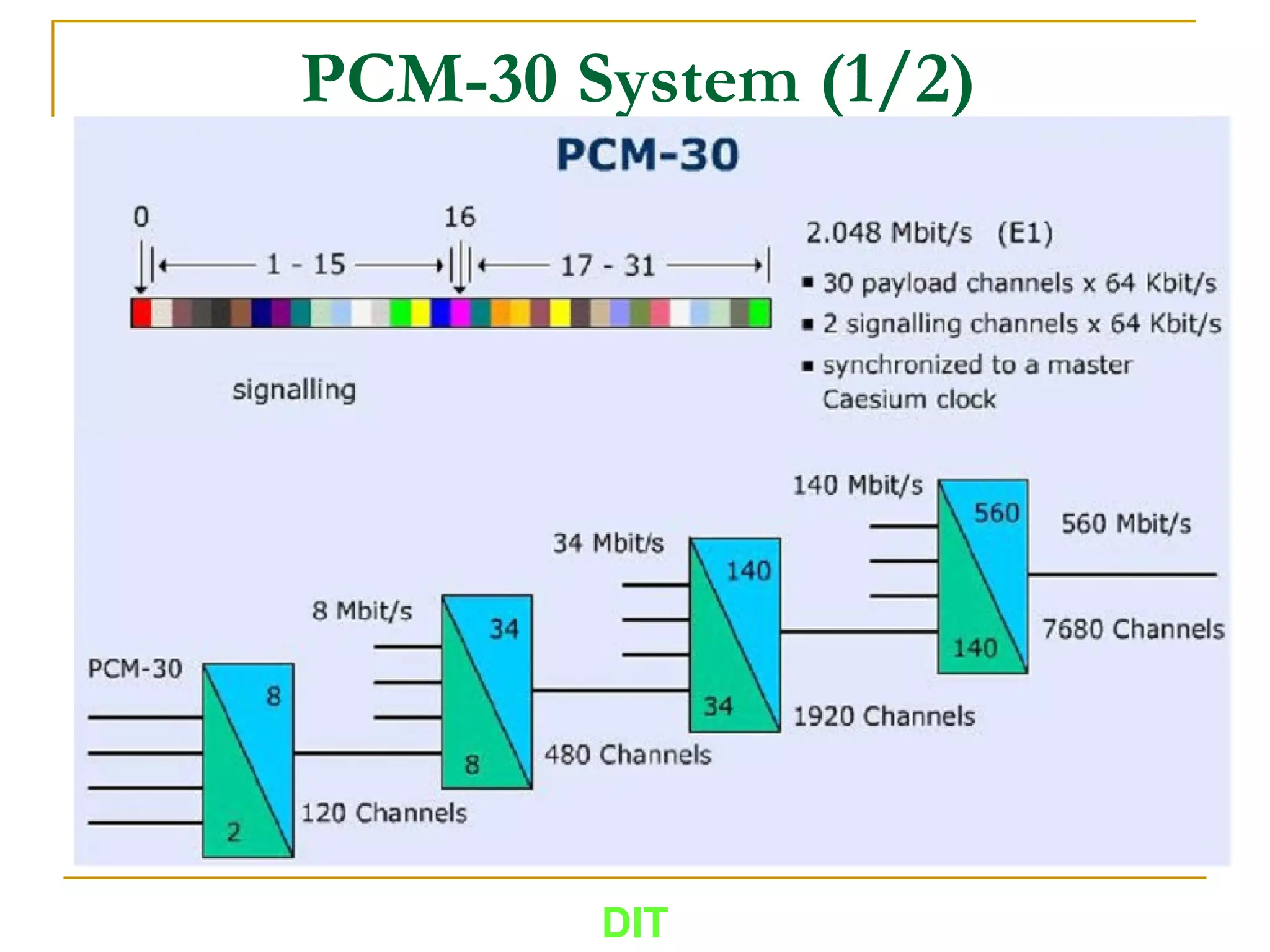
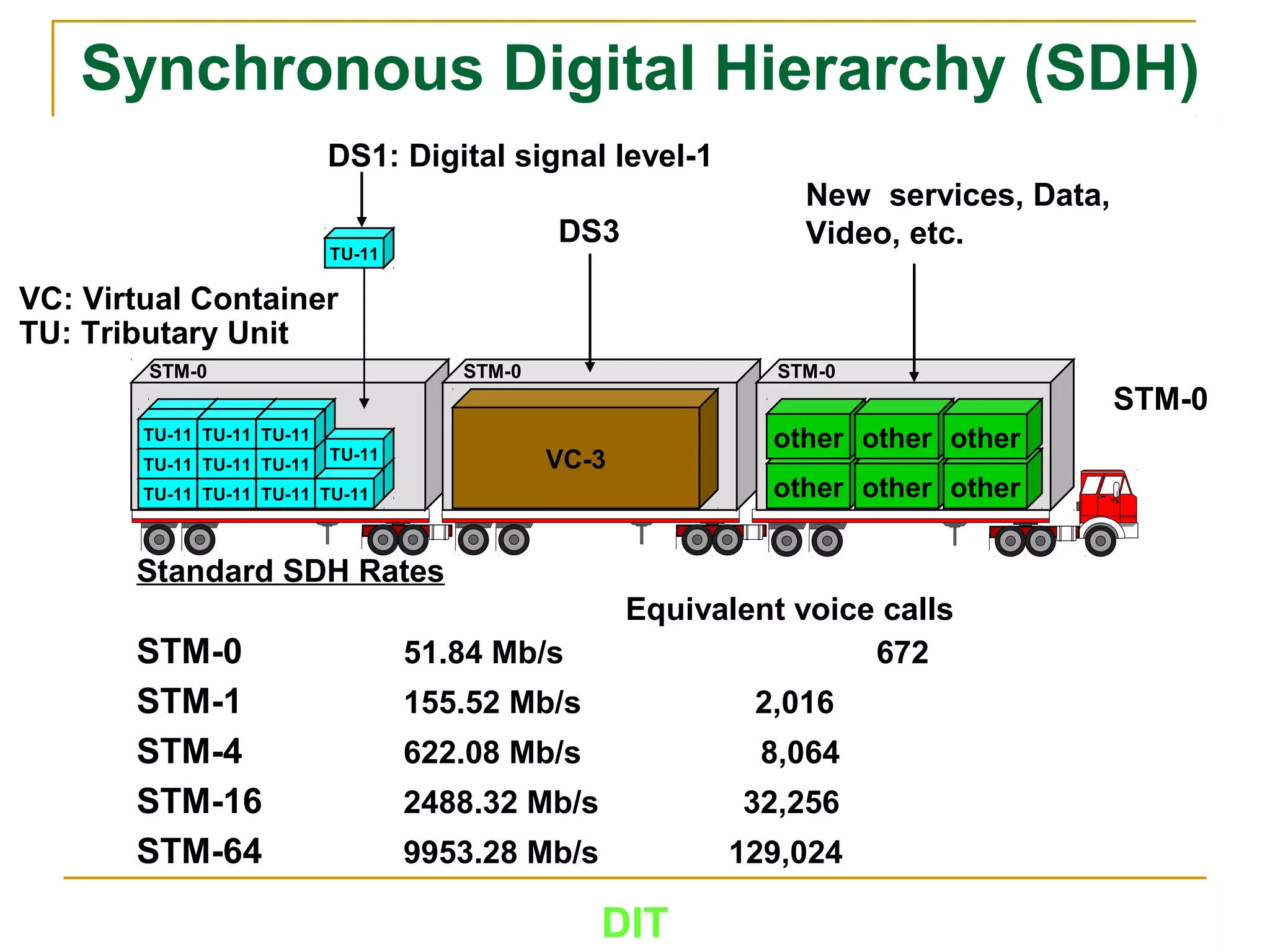
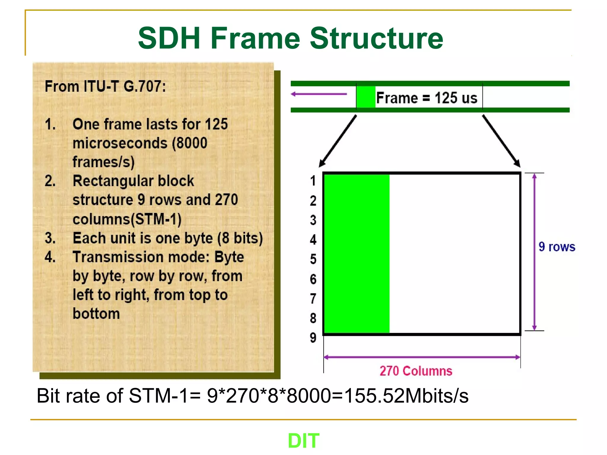
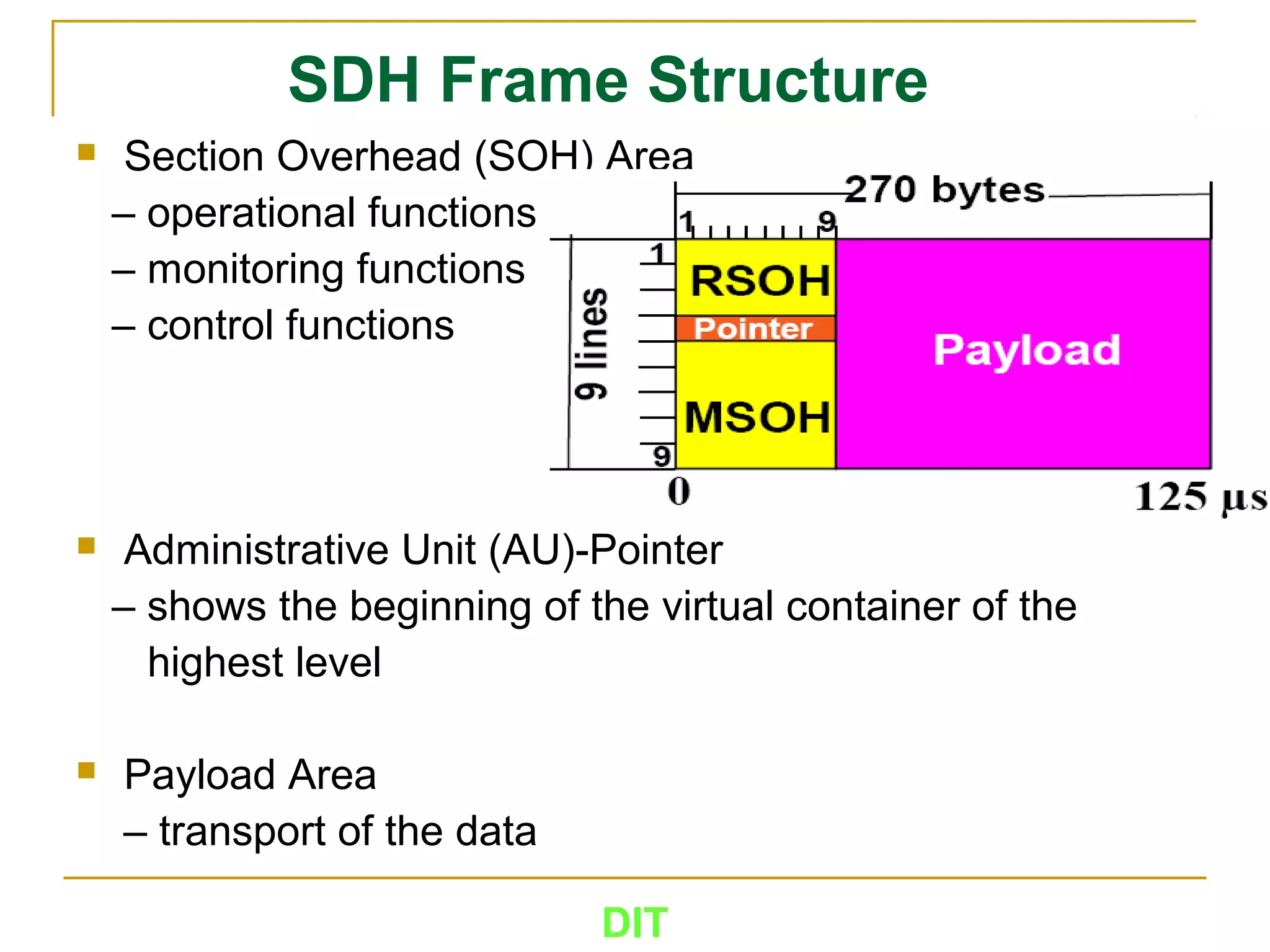
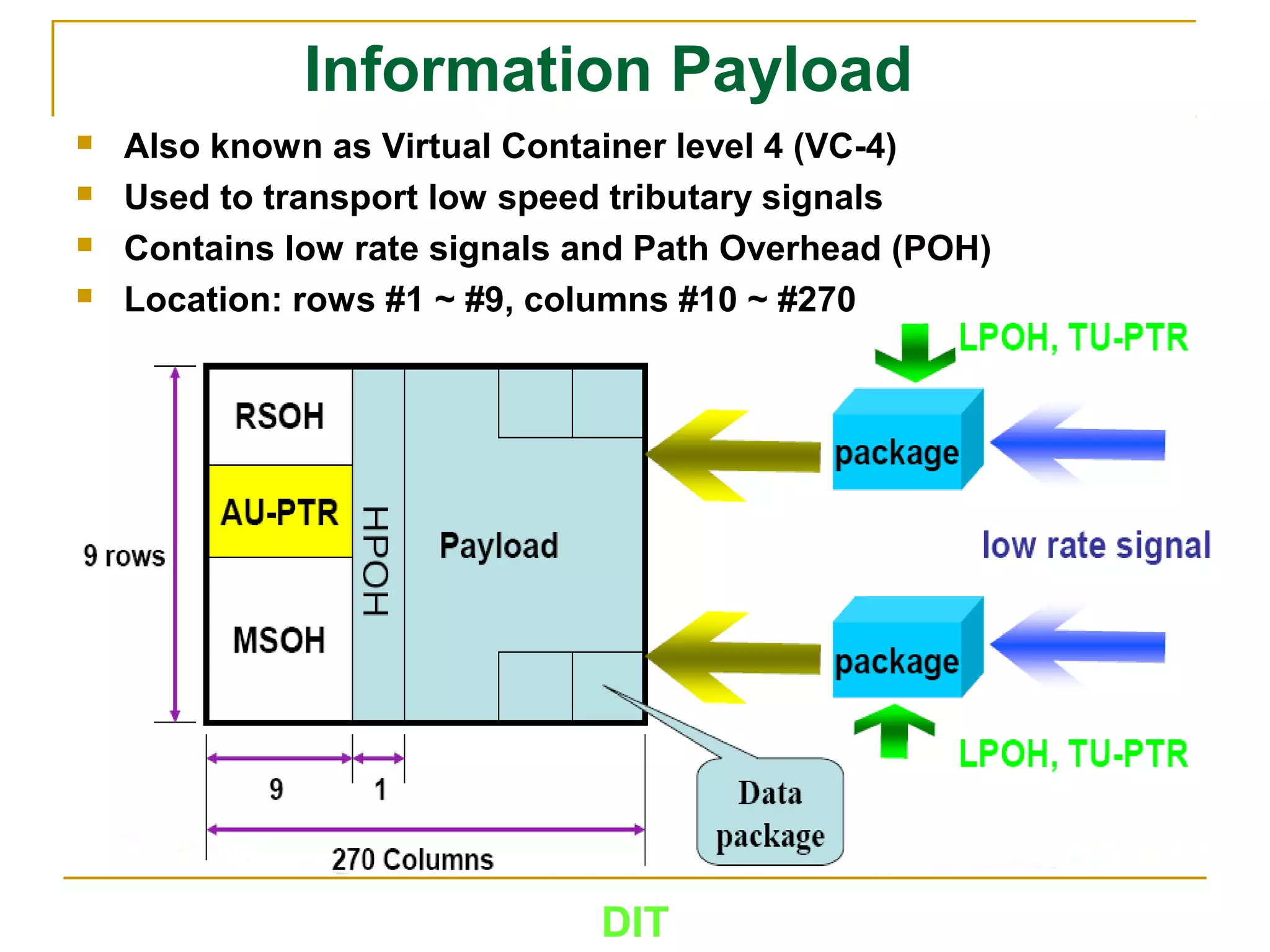
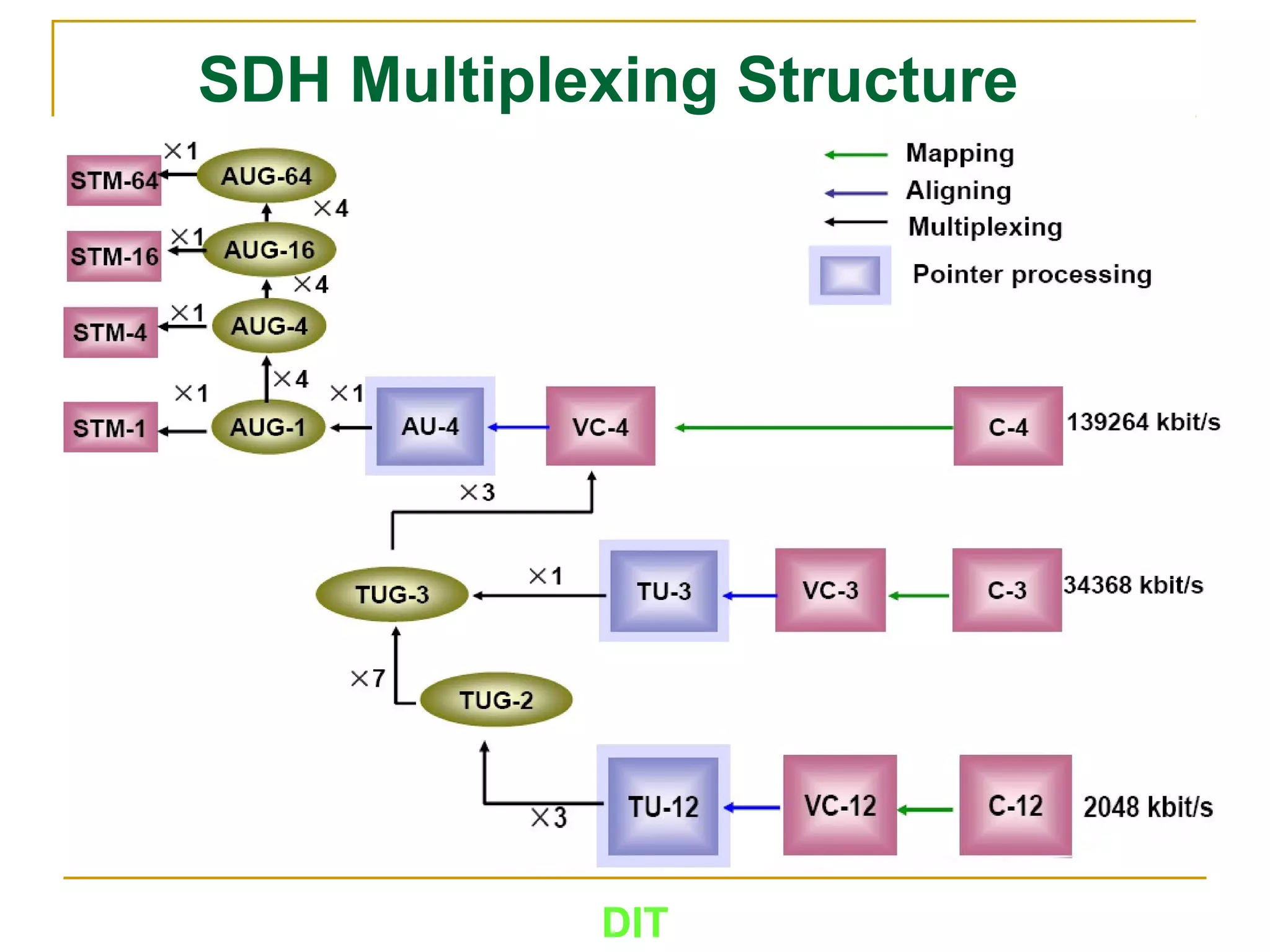
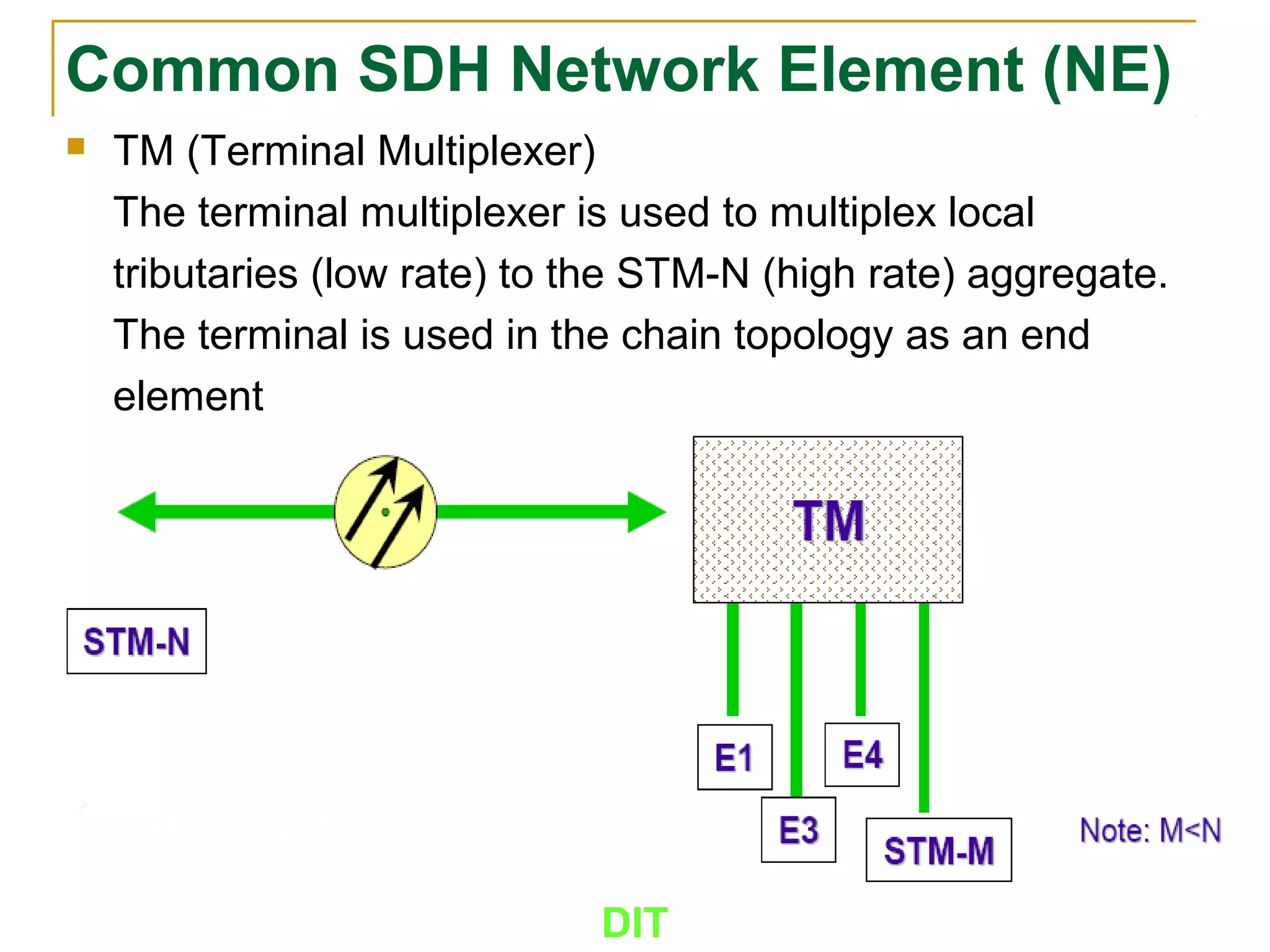
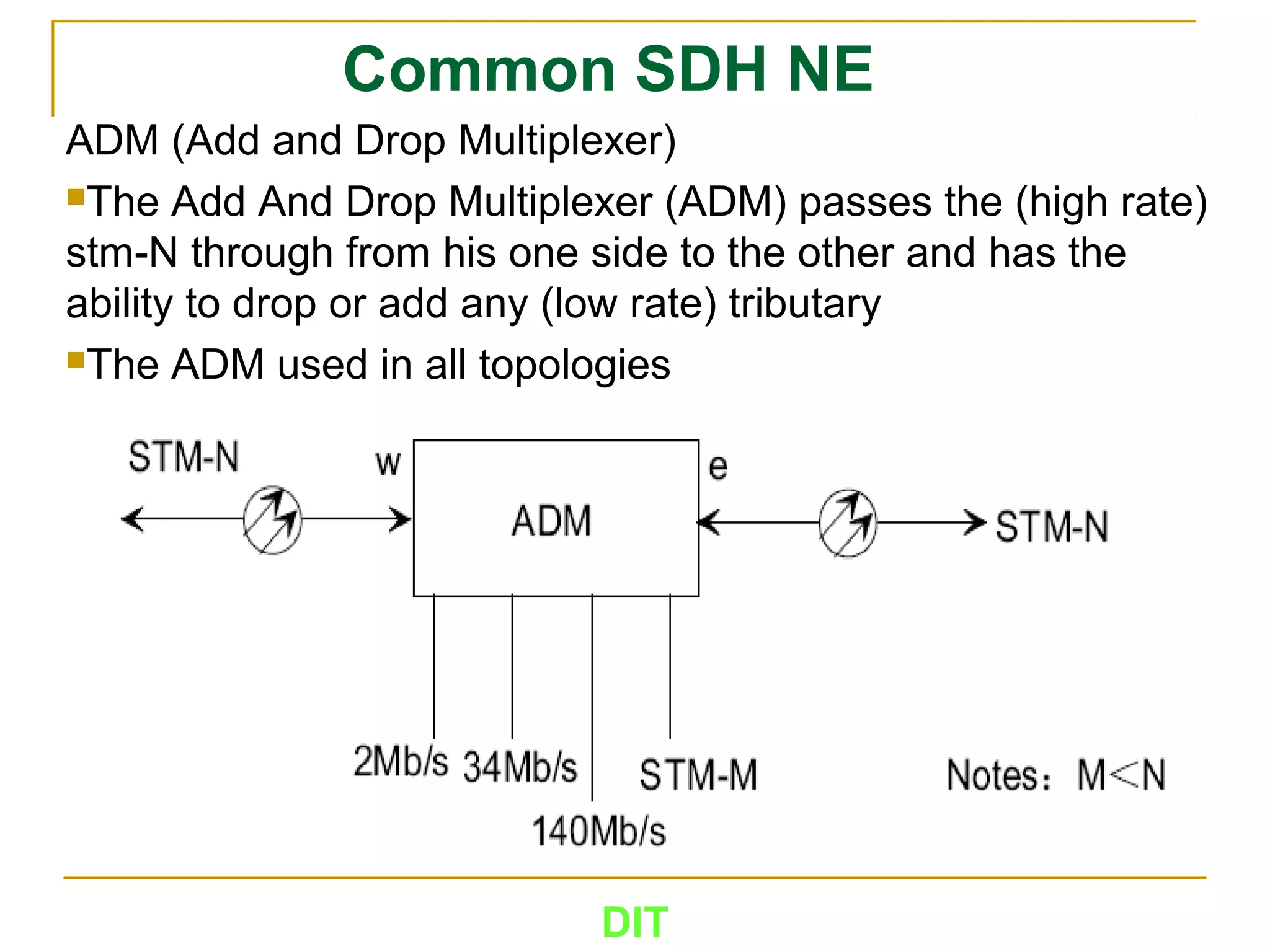
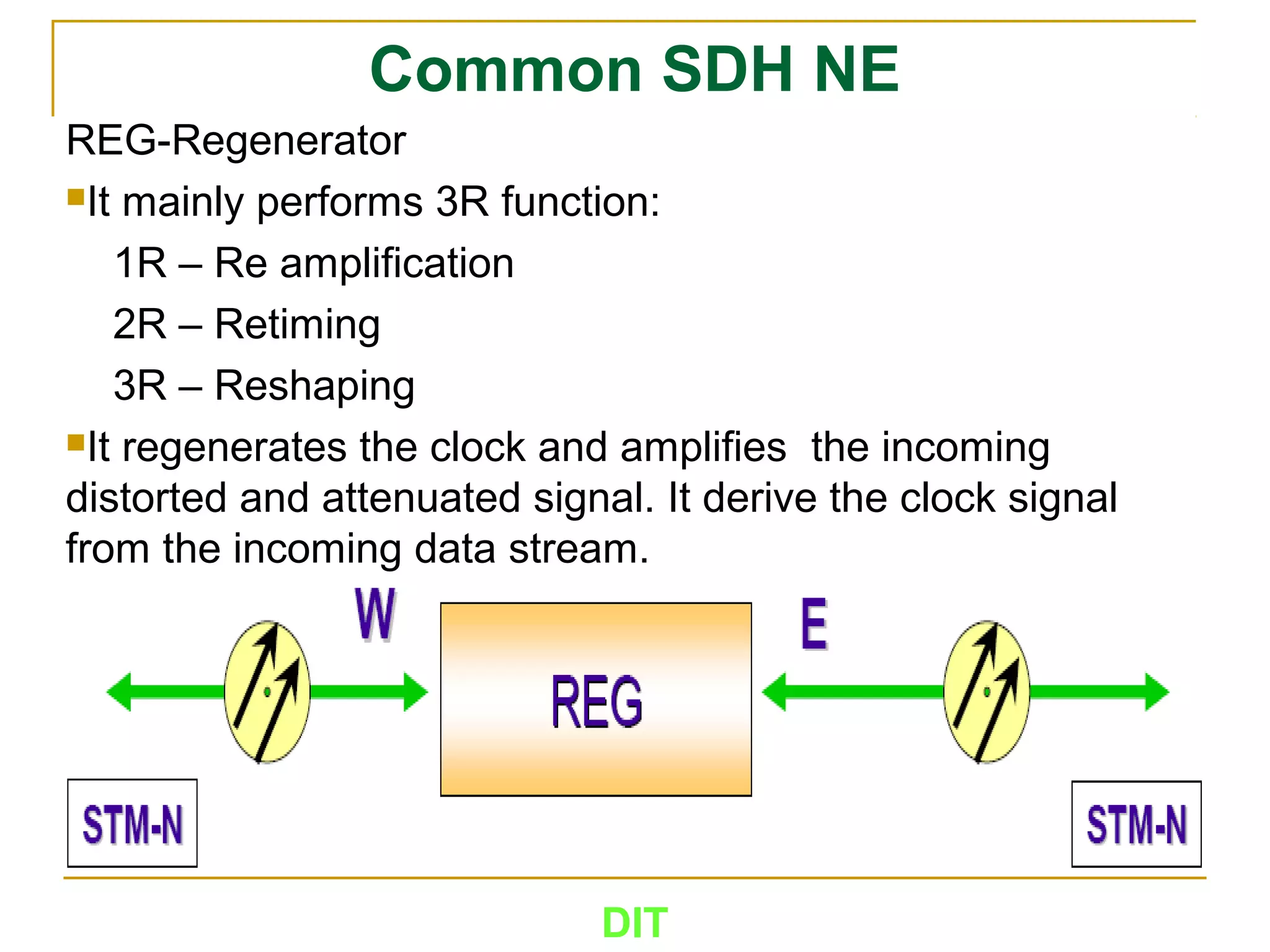
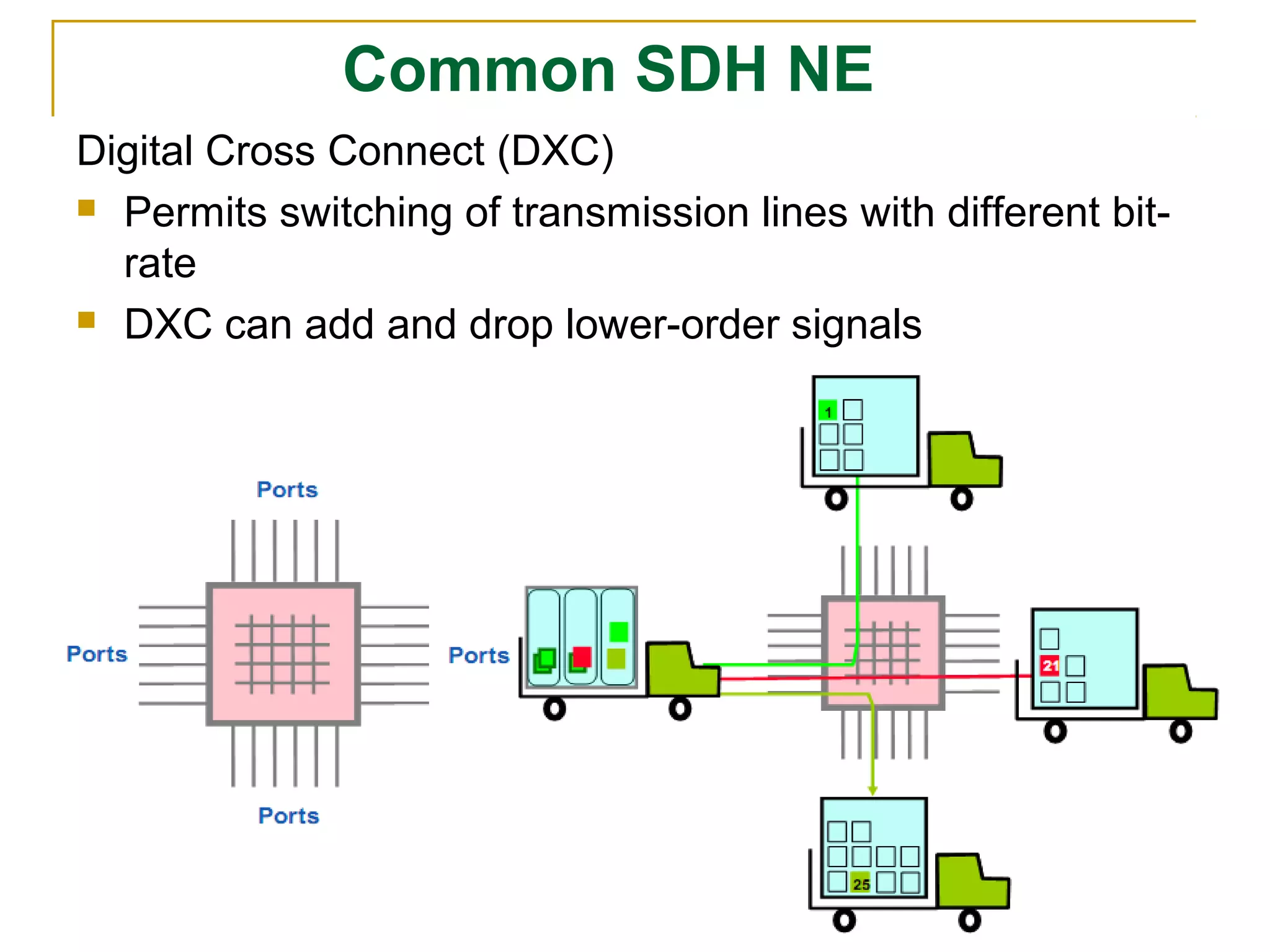
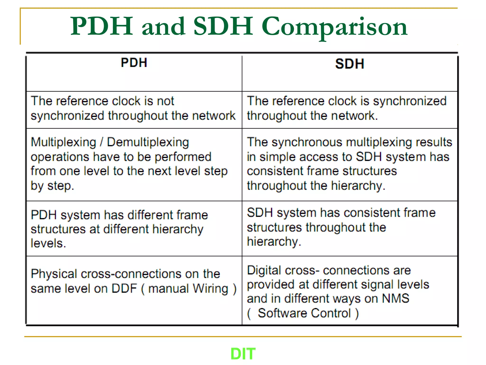
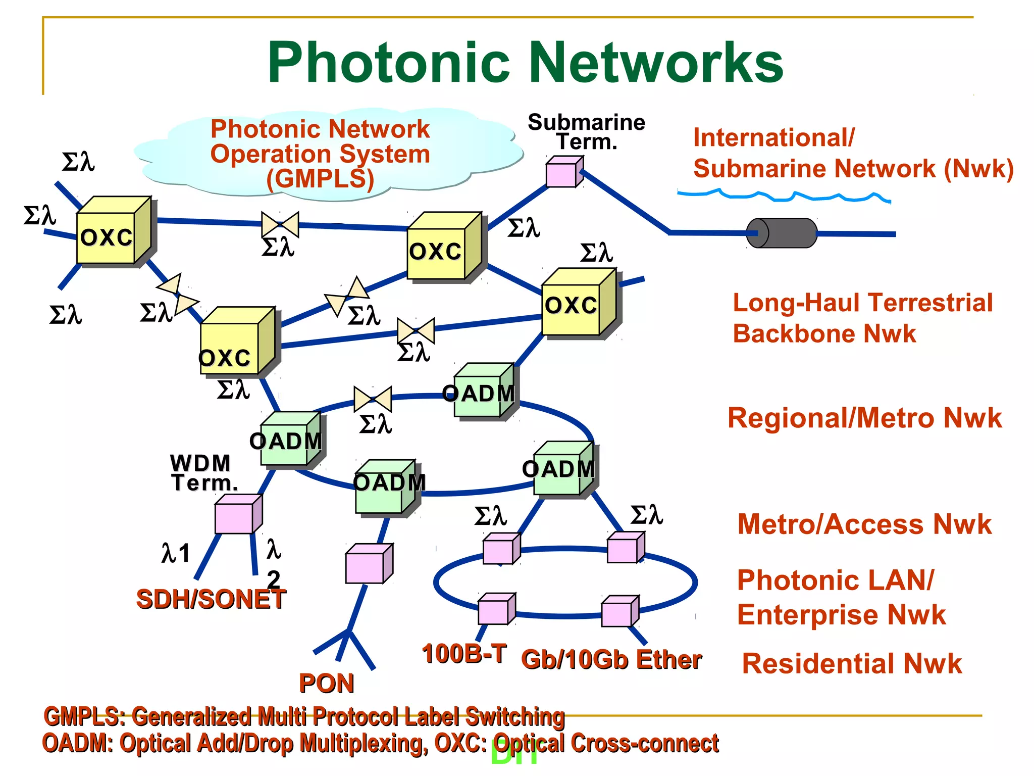
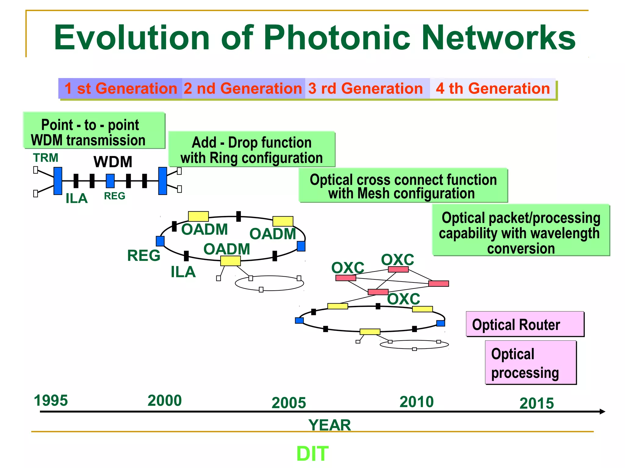
4. DIT
Introduction
What is Synchronous Digital Hierarchy (SDH)?
SDH is a transmission system (protocol) which defines the
characteristics of digital signals, including frame structure,
multiplexing method, digital rates hierarchy and interface code
pattern
A synchronous digital transport system aimed at providing a more
simple, economical, and flexible telecommunications network
infrastructure
An International Standard for a high capacity optical
telecommunication network
Why did SDH emerge?
Need for a system to process increasing amounts of information
New standard that allows mixing equipment from different suppliers
5. What is PDH?
The Plesiochronous Digital Hierarchy (PDH) is a technology
used in telecommunications networks to transport large
quantities of data over digital transport equipment such as
fibre optic and microwave radio systems.
PDH networks run in a state where different parts of the
network are nearly, but not quite perfectly, synchronized.
PDH allows transmission of data streams that are nominally
running at the same rate, but allowing some variation on the
speed around a nominal rate
By analogy, any two watches are nominally running at the
same rate, clocking up 60 seconds every minute.
However, there is no link between watches to guarantee
they run at exactly the same rate, and it is highly likely that
one is running slightly faster than the other
DIT
7. PCM-30 System (2/2)
Digital data and voice transmission is based on a 2.048 Mbit/s
bearer consisting of 30 time division multiplexed (TDM)
channels, each running at 64 Kbps.
The 2.048 Mbit/s bearer is known as E1. Channel 0 and 16 are
used to transmit additional signaling information within the
PCM-30 frame.
Increasing traffic over the past decade has demanded that more
and more of these basic E1 bearers be multiplexed together to
provide increased capacity.
At the same time, rates have increased through 8, 34, and 140
Mbit/s.
The highest capacity commonly encountered today for
intercity fibre optic links is 565 Mbit/s, with each link carrying
7,680 base channels, and now even this is insufficient.
DIT
9. PDH Multiplexing
The common base for the multiplex levels of plesiochronous bearers is
represented by the 64 kbit/s channel.
One branch describes the multiplex levels of plesiochronous bearers in the
Japanese standard, one further branch shows the multiplex levels of the
American standard and a third one describes the conditions of the European
standard.
Within the European standard the multiplex level 1 is made up of bearers with
a data rate of 2.048 Mbit/s. This rate is formed by the PCM-30 frame.
The Japanese and American standards possess a data rate of 1.544 Mbit/s. In
this case, 24 channels of 64 kbit/s each are multiplexed together. Multiplex
level 2 is achieved by multiplexing 4 bearers of level 1.
For the Japanese and American standards, this represents a multiplexed data
rate of 6.321 Mbit/s. The European standard has a combined data rate of 8.448
Mbit/s for multiplex level 2.
In the European multiplex structure 4 bearers each of the corresponding
hierarchical level are multiplexed together to obtain the bearer for the next
higher multiplex level.
DIT
10. Limitation of PDH
Existing PDH is point to point system
Optical Fiber capacity is under utilized
Difficulty in centralized supervision
Restoration of fault is time consuming
Manpower requirement is more
If 140 Mbps is passing through and the customer
wants one 2 Mbps, then we have to Demultiplex
from 140 Mbps to 2 Mbps for providing the 2 Mbps
The use of Justification Bits at different levels of
multiplexing means that locating the 2 Mbps in 140
Mbps is not possible
DIT
12. Why use SDH ?
No world standard on digital format (three
incompatible regional standards - European,
North American and Japanese)
No world standard for optical interfaces
Networking is impossible at the optical level
Rigid asynchronous multiplexing structure
Limited management capability
DIT
13. When do we use SDH ?
When networks need to increase capacity,
SDH simply acts as a means of increasing
transmission capacity
When networks need to improve flexibility, to
provide services quickly or to respond to new
change more rapidly
When networks need to improve survivability
for important user services
When networks need to reduce operation
costs, which are becoming a heavy burden
DIT
15. SDH Advantages
First world standard in digital format
First optical Interfaces
Transversal compatibility reduces networking cost.
Multi-vendor environment drives price down
Flexible synchronous multiplexing structure
Easy and cost-efficient traffic add-and-drop and cross
connect capability
Network survivability
Auto restoration of faults in no time
Optimum utilization of optical Fiber Bandwidth
Centralized supervision by NMS, Less manpower
required
DIT
16. SDH Advantages
Upgradation of system is easy
Existing PDH can work on SDH
Network Simplification- A single synchronous
multiplexer can perform the multiplexing function
Future Proof Networking – SDH is able to handle
video on demand and all other new systems like ATM,
Ethernet, DVB, etc.
As the number of equipment are reduced, the space,
power consumption & the maintenance cost also
reduced
Bandwidth on demand - Any bandwidth required by
customer can be provided in short notice
DIT
19. DIT
SDH Evolution
SDH evolution is possible because of the following factors :
Fibre Optic Bandwidth : The bandwidth in Optical Fibre can be
increased and there is no limit for it. This gives a great advantage
for using SDH
Technical Sophistication : Although, SDH circuitary is highly
complicated, it is possible to have such circuitary because of VLSI
technique which is also very cost effective
Intelligence : The availability of cheaper memory opens new
possibilities
Customer Service Needs : The requirement of the customer with
respect to different bandwidth requirements could be easily met
without much additional equipment. The different services it
supports are :
1. Low/High speed data.
2. Voice
3. Interconnection of LAN
4. Computer links
5. Feature services like H.D.T.V.
6. Broadband ISDN transport (ATM transport)
20. DIT
Synchronous Digital Hierarchy (SDH)
VT1.5 VT1.5 VT1.5 VT1.5
VT1.5 VT1.5 VT1.5 TU-11
VT1.5 VT1.5 VT1.5
TU-11 TU-11 TU-11 TU-11
TU-11 TU-11 TU-11
TU-11 TU-11 TU-11
STM-0 STM-0 STM-0
VC-3
DS3
other
other
other
other
other
other
New services, Data,
Video, etc.
STM-0
Standard SDH Rates
Equivalent voice calls
STM-0 51.84 Mb/s 672
STM-1 155.52 Mb/s 2,016
STM-4 622.08 Mb/s 8,064
STM-16 2488.32 Mb/s 32,256
STM-64 9953.28 Mb/s 129,024
VC: Virtual Container
TU: Tributary Unit
TU-11
DS1: Digital signal level-1
22. DIT
SDH Frame Structure
Section Overhead (SOH) Area
– operational functions
– monitoring functions
– control functions
Administrative Unit (AU)-Pointer
– shows the beginning of the virtual container of the
highest level
Payload Area
– transport of the data
23. DIT
Information Payload
Also known as Virtual Container level 4 (VC-4)
Used to transport low speed tributary signals
Contains low rate signals and Path Overhead (POH)
Location: rows #1 ~ #9, columns #10 ~ #270
26. DIT
Why do we need pointer
Neighboring network elements (NEs) may have different
bit rates
In one NE the frequency of input fin may differ from the
output fout
Tasks of the Pointer
• The pointer shows the begin of the Virtual Container
within the higher structure
• Adaptation of the bit rate of the VC to the velocity of the
transport channel (AU, TU)
• A flag within the pointer signals the changes made
• Kind of stuffing will be signalized also
27. DIT
SDH Multiplexing
SDH Multiplexing includes:
Low to high rate SDH signals (STM-1 STM-N)
PDH to SDH signals (2M, 34M & 140M STM-N)
Other hierarchy signals to SDH Signals (ATM STM-N)
Some terms and definitions:
Mapping - A process used when tributaries are adapted
into VCs by adding POH information
Aligning - This process takes place when a pointer is
included in a Tributary Unit (TU) or an Administrative Unit
(AU), to allow the 1st byte of the VC to be located
Multiplexing - This process is used when multiple low
order path signals are adapted into a higher-order path
signal, or when high-order path signals are adapted into a
Multiplexing Section
29. DIT
STM-1 Signals as Transport Pipe
A STM-1 Signal Can Transport:
One 140 Mbit/s PDH Signal
Three 34 Mbit/s PDH Signals
Sixty-three 2 Mbit/s PDH Signals
Combinations, eg. twenty-one 2 Mbit/s and Two 34
Mbit/s PDH Signals
ATM cells, FDDI, DQDB Protocols, etc.
30. DIT
Common SDH Network Element (NE)
TM (Terminal Multiplexer)
The terminal multiplexer is used to multiplex local
tributaries (low rate) to the STM-N (high rate) aggregate.
The terminal is used in the chain topology as an end
element
31. DIT
Common SDH NE
ADM (Add and Drop Multiplexer)
The Add And Drop Multiplexer (ADM) passes the (high rate)
stm-N through from his one side to the other and has the
ability to drop or add any (low rate) tributary
The ADM used in all topologies
32. DIT
Common SDH NE
REG-Regenerator
It mainly performs 3R function:
1R – Re amplification
2R – Retiming
3R – Reshaping
It regenerates the clock and amplifies the incoming
distorted and attenuated signal. It derive the clock signal
from the incoming data stream.
33. DIT
Common SDH NE
Digital Cross Connect (DXC)
Permits switching of transmission lines with different bit-
rate
DXC can add and drop lower-order signals
37. DIT
Evolution of Photonic Networks
Optical
processing
Optical
processing
OXC
Optical RouterOptical Router
YEAR
1995 2000 2005 2010
1 st Generation 2 nd Generation 3 rd Generation 4 th Generation
REGILA
TRM WDM
Point - to - point
WDM transmission Add - Drop function
with Ring configuration
Optical cross connect function
with Mesh configuration
Optical packet/processing
capability with wavelength
conversionOADM
ILA
REG
OADMOADM
OXC
OXC
2015
Each step increase in capacity was made by adding yet another layer of multiplexing. This was to maintain the large investments made in earlier generations of plesiochronous transmission equipment. This has created the situation where each data link has a rigid physical and electrical multiplexing hierarchy at either end. Once multiplexed, there is no simple way an individual E1 bearer can be identified, let alone extracted, without fully demultiplexing down to the E1 level again as shown in the animation.
Functions and characteristics of the Path Overhead (POH)
• includes path trace identifier, alarm signals and operational signals
• secures the transport of a container to the desired destination
Functions and characteristics of the Section Overhead (SOH)
• includes operation, monitoring and controlling functions
• each byte is equivalent to an 64-kbit/s channel
• in regenerators only the first three lines are accessable
• in multiplexers the last five lines are accessable
• preserves the connections from the point of creation until the point of decomposition
Tasks of the Pointer
• the pointer shows the begin of the Virtual Container within the higher structure
• adaptation of the bitrate of the VC to the velocity of the tranport channel (AU, TU)
• a flag within the pointer signals the changes made
• kind of stuffing will be signalized also