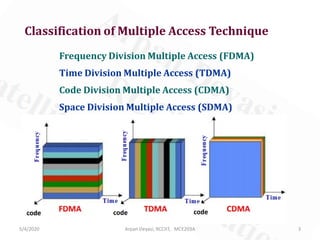
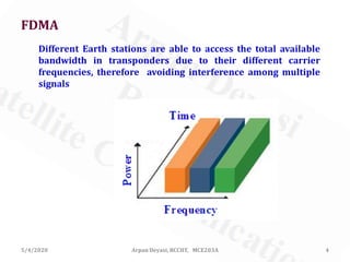
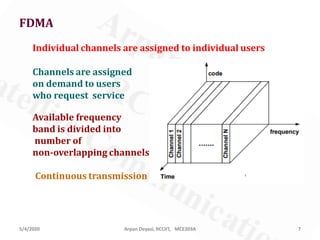
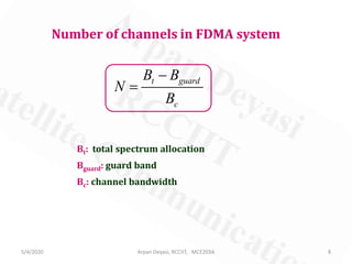
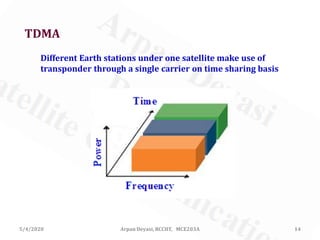
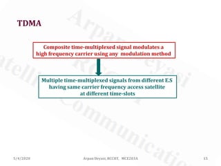
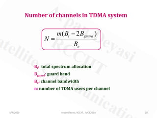
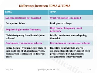
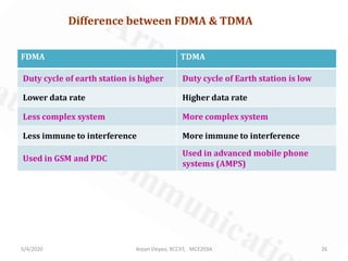
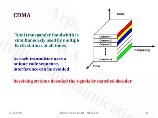
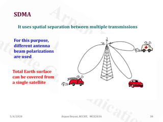
Arpan Deyasi
Dept of ECE, RCCIIT, Kolkata, India
Course: MCE203A
Multiple Access Techniques
used in Satellite Communication
5/4/2020 1Arpan Deyasi, RCCIIT, MCE203A
What is multiple access?
Access to a given facility or a resource by multiple users
Facility: Transponder
Multiple users: Different channels under the satellite
5/4/2020 2Arpan Deyasi, RCCIIT, MCE203A
Classification of Multiple Access Technique
Frequency Division Multiple Access (FDMA)
Time Division Multiple Access (TDMA)
Code Division Multiple Access (CDMA)
Space Division Multiple Access (SDMA)
5/4/2020 3Arpan Deyasi, RCCIIT, MCE203A
FDMA
Different Earth stations are able to access the total available
bandwidth in transponders due to their different carrier
frequencies, therefore avoiding interference among multiple
signals
5/4/2020 4Arpan Deyasi, RCCIIT, MCE203A
FDMA
Multiple baseband signals modulate different carrier
frequencies (subcarrier frequencies)
Multiplexed signal then modulates higher carrier frequency
This signal is transmitted from Earth station(1)
E.S(2), … , E.S(n) also send different carrier frequencies
These multiplexed signals access satellite simultaneously
5/4/2020 5Arpan Deyasi, RCCIIT, MCE203A
Are FDMA & FDM same?
No.
FDM is the process of grouping multiple baseband
signals into a single signal for transmission through a
single channel without multiple baseband signals
5/4/2020 6Arpan Deyasi, RCCIIT, MCE203A
5/4/2020 Arpan Deyasi, RCCIIT, MCE203A 7
FDMA
Individual channels are assigned to individual users
Channels are assigned
on demand to users
who request service
Available frequency
band is divided into
number of
non-overlapping channels
Continuous transmission
5/4/2020 Arpan Deyasi, RCCIIT, MCE203A 8
Number of channels in FDMA system
t guard
c
B B
N
B
−
=
Bt: total spectrum allocation
Bguard: guard band
Bc: channel bandwidth
5/4/2020 Arpan Deyasi, RCCIIT, MCE203A 9
Calculation of Carrier-to-Noise Ratio
Overall N/C ratio of a satellite link is
1 1 1 1
net U D IM
C C C C
N N N N
− − − −
       
= + +       
       
As per design
specification
1 1
net REQ
C C
N N
− −
   
≥   
   
1 1 1 1
REQ U D IM
C C C C
N N N N
− − − −
       
≤ + +       
       
5/4/2020 Arpan Deyasi, RCCIIT, MCE203A 10
Calculation of Carrier-to-Noise Ratio
Intemodulation noise is brought to an acceptable level by
employing backoff in power amplifiers
Uplink noise is negligible
REQ D
C C
N N
   
≤   
   
For downlink (in dB scale)
5/4/2020 Arpan Deyasi, RCCIIT, MCE203A 11
Calculation of Carrier-to-Noise Ratio
( ) ( ) BD D
REQ D
C G
EIRP LOSS k B
N T
   
≤ + − − −   
   
B: signal bandwidth, equals to noise bandwidth
( ) ( ) BD D
D D
C G
EIRP LOSS k B
N T
   
= + − − −   
   
5/4/2020 Arpan Deyasi, RCCIIT, MCE203A 12
FDMA: Advantages
Very efficient when traffic is uniformly constant
Simple equipments required for earth station
No complex timing and synchronization technique required
No restriction regarding modulation technique used
FDMA
One phone circuit at a time per carrier
Low Inter-Symbol Interference
5/4/2020 Arpan Deyasi, RCCIIT, MCE203A 13
FDMA: Disadvantages
Intermodulation problem occurs which affects SNR
Adjacent channel interference
RF filter required which increases cost of the system
TDMA
Different Earth stations under one satellite make use of
transponder through a single carrier on time sharing basis
5/4/2020 14Arpan Deyasi, RCCIIT, MCE203A
TDMA
Composite time-multiplexed signal modulates a
high frequency carrier using any modulation method
Multiple time-multiplexed signals from different E.S
having same carrier frequency access satellite
at different time-slots
5/4/2020 15Arpan Deyasi, RCCIIT, MCE203A
Are TDMA & TDM same?
No.
In TDM, multiple based band signals are simultaneously
transmitted from a given earth station in digitized form
through a single channel in different time
5/4/2020 16Arpan Deyasi, RCCIIT, MCE203A
5/4/2020 Arpan Deyasi, RCCIIT, MCE203A 17
TDMA
Carrier frequency is divided into ‘N’ timeslots, which is
shared into ‘N’ terminals
Each user has a particular
timeslot
Discontinuous
transmission
5/4/2020 Arpan Deyasi, RCCIIT, MCE203A 18
5/4/2020 Arpan Deyasi, RCCIIT, MCE203A 19
Reference Burst
TDMA: frame structure
It is a combination of primary and secondary reference bursts
Primary is transmitted to primary reference station,
secondary is transmitted to secondary reference station
If primary fails, it automatically switches to secondary
It doesn’t carry any traffic information
It is used to provide timing references
5/4/2020 Arpan Deyasi, RCCIIT, MCE203A 20
Number of channels in TDMA system
( 2 )t guard
c
m B B
N
B
−
=
Bt: total spectrum allocation
Bguard: guard band
Bc: channel bandwidth
n: number of TDMA users per channel
5/4/2020 Arpan Deyasi, RCCIIT, MCE203A 21
TDMA: frame structure
Traffic Burst
These are positioned anywhere in the frame according
to a burst time plan
Timing reference is taken from time of reference from
primary reference burst
5/4/2020 Arpan Deyasi, RCCIIT, MCE203A 22
TDMA: frame structure
Guard Time
Separate different traffic bursts
It should be as low as possible
5/4/2020 Arpan Deyasi, RCCIIT, MCE203A 23
TDMA: Advantages
Flexible bit rate
No frequency guard band required
Narrowband filters not required
Cost-effective
Extended lifetime of source
5/4/2020 Arpan Deyasi, RCCIIT, MCE203A 24
TDMA: Disadvantages
Timing synchronization required
High peak power required for uplink
5/4/2020 Arpan Deyasi, RCCIIT, MCE203A 25
Difference between FDMA & TDMA
FDMA TDMA
Synchronization is not required Synchronization is required
Peak power is low Peak power is large
Requires high carrier frequency
High carrier frequency is not
necessary
Divide frequency band into disjoint
subband
Divide time into non overlapping
time-slot
Continuous transmission scheme Discontinuous transmission scheme
Entire band of frequencies is divided
into multiple RF channels/carriers,
each carrier is allocated to different
users
Its entire bandwidth is shared
among different subscribers at fixed
predetermined or dynamically
assigned time intervals/slots
5/4/2020 Arpan Deyasi, RCCIIT, MCE203A 26
Difference between FDMA & TDMA
FDMA TDMA
Duty cycle of earth station is higher Duty cycle of Earth station is low
Lower data rate Higher data rate
Less complex system More complex system
Less immune to interference More immune to interference
Used in GSM and PDC
Used in advanced mobile phone
systems (AMPS)
CDMA
Total transponder bandwidth is
simultaneously used by multiple
Earth stations at all times
As each transmitter uses a
unique code sequence,
interference can be avoided
Receiving stations decoded the signals by matched decoder
5/4/2020 27Arpan Deyasi, RCCIIT, MCE203A
5/4/2020 Arpan Deyasi, RCCIIT, MCE203A 28
CDMA
It is a part of Spread Spectrum Multiple Access technique –
more precisely Direct Sequence Multiple Access
Chip rate is always much higher than data rate
Consistently provides better capacity for voice and
data communications, allowing more subscribers to
connect at any given time
5/4/2020 Arpan Deyasi, RCCIIT, MCE203A 29
CDMA Schemes
Direct Sequence CDMA (DS-CDMA)
The original data signal is multiplied directly by the high chip
rate spreading code
Frequency Hopping CDMA (FH-CDMA)
The carrier frequency at which the original data signal is
transmitted is rapidly changed according to the spreading code
Time Hopping CDMA (TH-CDMA)
The original data signal is not transmitted continuously. Instead,
the signal is transmitted in short bursts where the times of the
bursts are decided by the spreading code
SDMA
It uses spatial separation between multiple transmissions
For this purpose,
different antenna
beam polarizations
are used
Total Earth surface
can be covered from
a single satellite
5/4/2020 30Arpan Deyasi, RCCIIT, MCE203A
5/4/2020 31Arpan Deyasi, RCCIIT, MCE203A
SDMA
Base stations track user when moving inside cover area
with same frequency
Optimizes the use of radio spectrum
5/4/2020 Arpan Deyasi RCCIIT MCE203A 32
A. K. Maini, V. Agarawal, “Satellite Communications”, Wiley, 1st Ed.,
2019
References
T. Pratt, C. Bostian, J. Allnutt, “Satellite Communications”, John
Wiley & Sons, 2nd Ed., 2003
S. Katiyar, “Satellite Communication”, S. K. Kataria & Sons, 1st Ed., 2007

Multiple access techniques

  • 1.
    Arpan Deyasi Dept ofECE, RCCIIT, Kolkata, India Course: MCE203A Multiple Access Techniques used in Satellite Communication 5/4/2020 1Arpan Deyasi, RCCIIT, MCE203A
  • 2.
    What is multipleaccess? Access to a given facility or a resource by multiple users Facility: Transponder Multiple users: Different channels under the satellite 5/4/2020 2Arpan Deyasi, RCCIIT, MCE203A
  • 3.
    Classification of MultipleAccess Technique Frequency Division Multiple Access (FDMA) Time Division Multiple Access (TDMA) Code Division Multiple Access (CDMA) Space Division Multiple Access (SDMA) 5/4/2020 3Arpan Deyasi, RCCIIT, MCE203A
  • 4.
    FDMA Different Earth stationsare able to access the total available bandwidth in transponders due to their different carrier frequencies, therefore avoiding interference among multiple signals 5/4/2020 4Arpan Deyasi, RCCIIT, MCE203A
  • 5.
    FDMA Multiple baseband signalsmodulate different carrier frequencies (subcarrier frequencies) Multiplexed signal then modulates higher carrier frequency This signal is transmitted from Earth station(1) E.S(2), … , E.S(n) also send different carrier frequencies These multiplexed signals access satellite simultaneously 5/4/2020 5Arpan Deyasi, RCCIIT, MCE203A
  • 6.
    Are FDMA &FDM same? No. FDM is the process of grouping multiple baseband signals into a single signal for transmission through a single channel without multiple baseband signals 5/4/2020 6Arpan Deyasi, RCCIIT, MCE203A
  • 7.
    5/4/2020 Arpan Deyasi,RCCIIT, MCE203A 7 FDMA Individual channels are assigned to individual users Channels are assigned on demand to users who request service Available frequency band is divided into number of non-overlapping channels Continuous transmission
  • 8.
    5/4/2020 Arpan Deyasi,RCCIIT, MCE203A 8 Number of channels in FDMA system t guard c B B N B − = Bt: total spectrum allocation Bguard: guard band Bc: channel bandwidth
  • 9.
    5/4/2020 Arpan Deyasi,RCCIIT, MCE203A 9 Calculation of Carrier-to-Noise Ratio Overall N/C ratio of a satellite link is 1 1 1 1 net U D IM C C C C N N N N − − − −         = + +                As per design specification 1 1 net REQ C C N N − −     ≥        1 1 1 1 REQ U D IM C C C C N N N N − − − −         ≤ + +               
  • 10.
    5/4/2020 Arpan Deyasi,RCCIIT, MCE203A 10 Calculation of Carrier-to-Noise Ratio Intemodulation noise is brought to an acceptable level by employing backoff in power amplifiers Uplink noise is negligible REQ D C C N N     ≤        For downlink (in dB scale)
  • 11.
    5/4/2020 Arpan Deyasi,RCCIIT, MCE203A 11 Calculation of Carrier-to-Noise Ratio ( ) ( ) BD D REQ D C G EIRP LOSS k B N T     ≤ + − − −        B: signal bandwidth, equals to noise bandwidth ( ) ( ) BD D D D C G EIRP LOSS k B N T     = + − − −       
  • 12.
    5/4/2020 Arpan Deyasi,RCCIIT, MCE203A 12 FDMA: Advantages Very efficient when traffic is uniformly constant Simple equipments required for earth station No complex timing and synchronization technique required No restriction regarding modulation technique used FDMA One phone circuit at a time per carrier Low Inter-Symbol Interference
  • 13.
    5/4/2020 Arpan Deyasi,RCCIIT, MCE203A 13 FDMA: Disadvantages Intermodulation problem occurs which affects SNR Adjacent channel interference RF filter required which increases cost of the system
  • 14.
    TDMA Different Earth stationsunder one satellite make use of transponder through a single carrier on time sharing basis 5/4/2020 14Arpan Deyasi, RCCIIT, MCE203A
  • 15.
    TDMA Composite time-multiplexed signalmodulates a high frequency carrier using any modulation method Multiple time-multiplexed signals from different E.S having same carrier frequency access satellite at different time-slots 5/4/2020 15Arpan Deyasi, RCCIIT, MCE203A
  • 16.
    Are TDMA &TDM same? No. In TDM, multiple based band signals are simultaneously transmitted from a given earth station in digitized form through a single channel in different time 5/4/2020 16Arpan Deyasi, RCCIIT, MCE203A
  • 17.
    5/4/2020 Arpan Deyasi,RCCIIT, MCE203A 17 TDMA Carrier frequency is divided into ‘N’ timeslots, which is shared into ‘N’ terminals Each user has a particular timeslot Discontinuous transmission
  • 18.
    5/4/2020 Arpan Deyasi,RCCIIT, MCE203A 18
  • 19.
    5/4/2020 Arpan Deyasi,RCCIIT, MCE203A 19 Reference Burst TDMA: frame structure It is a combination of primary and secondary reference bursts Primary is transmitted to primary reference station, secondary is transmitted to secondary reference station If primary fails, it automatically switches to secondary It doesn’t carry any traffic information It is used to provide timing references
  • 20.
    5/4/2020 Arpan Deyasi,RCCIIT, MCE203A 20 Number of channels in TDMA system ( 2 )t guard c m B B N B − = Bt: total spectrum allocation Bguard: guard band Bc: channel bandwidth n: number of TDMA users per channel
  • 21.
    5/4/2020 Arpan Deyasi,RCCIIT, MCE203A 21 TDMA: frame structure Traffic Burst These are positioned anywhere in the frame according to a burst time plan Timing reference is taken from time of reference from primary reference burst
  • 22.
    5/4/2020 Arpan Deyasi,RCCIIT, MCE203A 22 TDMA: frame structure Guard Time Separate different traffic bursts It should be as low as possible
  • 23.
    5/4/2020 Arpan Deyasi,RCCIIT, MCE203A 23 TDMA: Advantages Flexible bit rate No frequency guard band required Narrowband filters not required Cost-effective Extended lifetime of source
  • 24.
    5/4/2020 Arpan Deyasi,RCCIIT, MCE203A 24 TDMA: Disadvantages Timing synchronization required High peak power required for uplink
  • 25.
    5/4/2020 Arpan Deyasi,RCCIIT, MCE203A 25 Difference between FDMA & TDMA FDMA TDMA Synchronization is not required Synchronization is required Peak power is low Peak power is large Requires high carrier frequency High carrier frequency is not necessary Divide frequency band into disjoint subband Divide time into non overlapping time-slot Continuous transmission scheme Discontinuous transmission scheme Entire band of frequencies is divided into multiple RF channels/carriers, each carrier is allocated to different users Its entire bandwidth is shared among different subscribers at fixed predetermined or dynamically assigned time intervals/slots
  • 26.
    5/4/2020 Arpan Deyasi,RCCIIT, MCE203A 26 Difference between FDMA & TDMA FDMA TDMA Duty cycle of earth station is higher Duty cycle of Earth station is low Lower data rate Higher data rate Less complex system More complex system Less immune to interference More immune to interference Used in GSM and PDC Used in advanced mobile phone systems (AMPS)
  • 27.
    CDMA Total transponder bandwidthis simultaneously used by multiple Earth stations at all times As each transmitter uses a unique code sequence, interference can be avoided Receiving stations decoded the signals by matched decoder 5/4/2020 27Arpan Deyasi, RCCIIT, MCE203A
  • 28.
    5/4/2020 Arpan Deyasi,RCCIIT, MCE203A 28 CDMA It is a part of Spread Spectrum Multiple Access technique – more precisely Direct Sequence Multiple Access Chip rate is always much higher than data rate Consistently provides better capacity for voice and data communications, allowing more subscribers to connect at any given time
  • 29.
    5/4/2020 Arpan Deyasi,RCCIIT, MCE203A 29 CDMA Schemes Direct Sequence CDMA (DS-CDMA) The original data signal is multiplied directly by the high chip rate spreading code Frequency Hopping CDMA (FH-CDMA) The carrier frequency at which the original data signal is transmitted is rapidly changed according to the spreading code Time Hopping CDMA (TH-CDMA) The original data signal is not transmitted continuously. Instead, the signal is transmitted in short bursts where the times of the bursts are decided by the spreading code
  • 30.
    SDMA It uses spatialseparation between multiple transmissions For this purpose, different antenna beam polarizations are used Total Earth surface can be covered from a single satellite 5/4/2020 30Arpan Deyasi, RCCIIT, MCE203A
  • 31.
    5/4/2020 31Arpan Deyasi,RCCIIT, MCE203A SDMA Base stations track user when moving inside cover area with same frequency Optimizes the use of radio spectrum
  • 32.
    5/4/2020 Arpan DeyasiRCCIIT MCE203A 32 A. K. Maini, V. Agarawal, “Satellite Communications”, Wiley, 1st Ed., 2019 References T. Pratt, C. Bostian, J. Allnutt, “Satellite Communications”, John Wiley & Sons, 2nd Ed., 2003 S. Katiyar, “Satellite Communication”, S. K. Kataria & Sons, 1st Ed., 2007