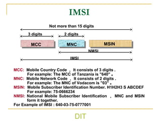
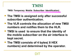
DIT
Dar es Salaam institute of Technology (DIT)
ETU 07420
Switching Systems
Ally, J
jumannea@gmail.com
DIT
Mobile Core Network Overview
DIT
GSM system overview
 The GSM system is a frequency- and time-division
cellular system, each physical channel is characterized
by a carrier frequency and a time slot number
 Cellular systems are designed to operate with groups of
low-power radios spread out over the geographical
service area. Each group of radios serve MSs presently
located near them. The area served by each group of
radios is called a CELL
 Uplink and downlink signals for one user are assigned
different frequencies, this kind of technique is called
Frequency Division Duplex (FDD)
 Data for different users is conveyed in time intervals
called slots , several slots make up a frame. This kind of
technique is called Time Division Multiple Access
(TDMA)
DIT
GSM Development
Standard Protocol for GSM take effect
System was named as Global System for
Mobile Communication
GSM system began to provide service in Europe(2G)
Provide services for the whole world
Micro Cell Technique is used in GSM system
1989
1991
1992
1994
1996
DIT
GSM-GPRS Network Component
GSM /GPRS BSS
BTS
BSC
BTS
BSC
PCU
SS7
SMS system
PSTN
ISDN
Internet,
Intranet
MSC/VLR GMSC
HLR/AUC
SGSN
CG BG
GGSN
GPRS Backbone
Other PLMN
MS
MS
OMC
DIT
Mobile Station—MS
International Mobile Equipment Identity (IMEI)
– Mobile Equipment
MS=ME+SIM
International Mobile Subscriber Identity (IMSI)
– Subscriber Identity Module
DIT
Subscriber Identity Module – SIM
 International Mobile Subscriber
Identity (IMSI)
 Temporary Mobile Subscriber Identity
(TMSI)
 Location Area Identity (LAI)
 Subscriber Authentication Key (Ki)
SIM
DIT
BTSBTS
BSCBSC
TC/SMTC/SM
BSS
MSC
Base Station Subsystem – BSS
 The Base Station
Controller – BSC
 The Base Transceiver
Station – BTS
 The Trans-coder – TC
and Sub multiplexer
(SM)
DIT
BTSBTS
BSCBSC
TC/SMTC/SM
BSS
MSC
Packet Control Unit-----PCU
 Packet data
switching
 Bridge between
SGSN and BSC
 Provide Pb and Gb
interface
GPRS
Backbone
PCUPCU SGSNSGSN
DIT
Mobile-service Switching Center – MSC
Home Location Register – HLR
Visitor Location Register – VLR
Equipment Identity Register – EIR
Authentication Center – AUC
Echo Cancellor – EC
AUCAUC
HLRHLR
MSC/VLRMSC/VLR
PSTN
NSS
EIREIROMC
BSS
ECEC
The Network Switching System
DIT
Mobile-Service Switching Center – MSC
 Call Processing
 Operations and Maintenance Support
 Interface management
 Inter-network & Inter-working
Inter-network: communication between GSM network
and other network
Inter-working : communication between different
entities inside the GSM network
 Billing
DIT
Home Location Register – HLR
 Subscriber ID (IMSI and MSISDN)
 Current subscriber VLR (current location)
 Supplementary service information
 Subscriber status (registered/deregistered)
 Authentication key and AuC functionality
DIT
Visitor Location Register – VLR
 Mobile Status (IMSI attached / detached /
busy / idle etc.)
 Location Area Identity (LAI)
 Temporary Mobile Subscriber Identity (TMSI)
 Allocating the Roaming Number
DIT
IMEI is Checked In White List
IMEI is Checked in Black/Grey List
If NOT found
EIR focus on the
equipment , not the
subscriber!!
Equipment Identity Register – EIR
 White List
 Black List
 Grey List
DIT
OMC Functional Architecture
OS
MMI
DB
Event/Alarm
Management
Security
Management
Configuration
Management
Performance
Management
Fault
Management
DIT
Service Area
PLMN service area
......
Service Area
MSC service area...
Location area...
cell
PLMN service area PLMN service area
MSC service area...
Location area...
cell
DIT
LAI
Location Area Identification
The LAI is the international code for a location area.
MCC: Mobile Country Code , It consists of 3 digits .
For example: The MCC of Tanzania is “640"
MNC: Mobile Network Code , It consists of 2 digits .
For example: The MNC of Vodacom is "03"
LAC: Location Area Code , It is a two bytes hex code.
The value 0000 and FFFF is invalid.
For example: 640-03-0011
MCC MNC LAC
DIT
CGI
The CGI is a unique international identification for a cell
The format is LAI+CI
LAI: Location Area Identification
CI: Cell Identity. This code uses two bytes hex code to
identify the cells within an LAI.
For example : 640-03-0011-0001
CGI: Cell Global Identification
DIT
BSIC
NCC: PLMN network color code. It comprises 3 bit. It
allows various neighboring PLMNs to be
distinguished.
BCC: BTS color code. It comprises 3 bit, used to
distinguish different cells assigned the same
frequency!
NCC BCC
BSIC
BSIC ( Base Station Identification Color Code)
DIT
CC: Country Code. For example: The CC of Tanzania is “255".
NDC: National Destination Code. For example: The NDC of
vodacomis 75 and 76.
SN: Subscriber Number. Format:H0 H1 H2 H3 ABCD
Example: 255-75-0666234
MSISDN
CC NDC SN
National (significant)
Mobile number
Mobile station international
ISDN number
DIT
MCC: Mobile Country Code , It consists of 3 digits .
For example: The MCC of Tanzania is "640" 。
MNC: Mobile Network Code , It consists of 2 digits .
For example: The MNC of Vodacom is "03" 。
MSIN: Mobile Subscriber Identification Number. H1H2H3 S ABCDEF
For example: 75-0666234
NMSI: National Mobile Subscriber Identification , MNC and MSIN
form it together.
For Example of IMSI : 640-03-75-0777001
Not more than 15 digits
3 digits 2 digits
IMSI
MCC MNC MSIN
NMSI
IMSI
DIT
TMSI
 The TMSI is assigned only after successful
subscriber authentication.
 The VLR controls the allocation of new TMSI
numbers and notifies them to the HLR.
 TMSI is used to ensure that the identity of
the mobile subscriber on the air interface is
kept secret.
 The TMSI consists of 4 bytes( 8 HEX
numbers) and determined by the operator.
TMSI: Temporary Mobile Subscriber Identification)
DIT
IMEI
TAC FAC SNR SP
IMEI
IMEI: International Mobile Station Equipment Identification
TAC: Type Approval Code, 6 bit, determined by the type approval
center
FAC: Final Assembly Code, 2 bit, It is determined by the
manufacturer.
SNR: Serial number, 6 bits, It is issued by the manufacturer of the
MS. SP: 1 bit , Not used.
Check the IMEI in your MS : *#06#
TAC: Type Approval Code, 6 bit, determined by the type approval
center
FAC: Final Assembly Code, 2 bit, It is determined by the
manufacturer.
SNR: Serial number, 6 bits, It is issued by the manufacturer of the
MS. SP: 1 bit , Not used.
Check the IMEI in your MS : *#06#
DIT
UMTS R99 Network Architecture
GSM /GPRS BSS
BTS
BSC
NodeB
RNC
PCU
UMTS
UTRAN
SS7
SCP
SMS
SCE
Other PLMN
PSTN,ISDN
Internet,
Intranet
MSC/VLR GMSC
HLR/AUC
SGSN
CG BG
GGSN
GPRS
backbone
Other PLMN’s
GPRS network
DIT
R99 CN Feature
 Core Network is split into CS domain and PS domain.
 CS domain is in charge of call control and mobility
management of circuit service.
 Call control: ISUP/TUP
 Mobility management: enhanced MAP
 Physical node:MSC,GMSC,VLR
 PS domain is in charge of session management and mobility
management of Packet service.
 There are some change from GPRS: interfaces, flows, some
functions
 Physical node: SGSN,GGSN,CG
 Transcoders is placed in CN side
 TFO: Tandem Free Operation
 Supporting inter-system handover (UMTS/GSM)
DIT
UMTS R4 Network Architecture
GSM /GPRS BSS
BTS
BSC
NodeB
RNC
PCU
UMTS
UTRAN
SS7
SCP
SMS
SCE
Internet,
Intranet
HLR/AUC
SGSN
CG BG
GGSN
MGWMGW MGWMGW
VMSC Server GMSC Server
IP/ATM Backbone
Other PLMN
PSTN,ISDN
Other PLMN’s
GPRS network
GPRS
backbone
DIT
R4 CN Feature
 CS domain
 Control is separated from bearer,MSC is split
into MSC server and MGW
 Traffic bearer can be IP , ATM or TDM
 Signaling bearer can be IP or TDM
 TrFO: Transcoder Free Operation
DIT
MSC
SCP HLR
MSC
RAN RAN RAN
TDM
MSC Server
SCP HLR
RAN RAN RAN
TDM/ATM/IP
CS-MGW CS-MGW
MSC ServerTUP/ISUP/BICC
TUP/ISUP
Notes: PS domain structure remain unchanged
R99 R4
H.248 H.248
MAP Over TDM MAP Over TDM/IPCAP Over TDM CAP Over TDM/IP
CS domain evolution
Difference Between R99 and R4
DIT
Interfaces in R99 network
GSM /GPRS BSS
BTS
BSC
NodeB
RNC
PCU
UMTS
UTRAN
SS7
SCP
SMS
SCE
PSTN
ISDN
Internet,
Intranet
MSC/VLR GMSC
HLR/AUC
SGSN
CG BG
GGSN
Other PLMN
A
Gb
Iu-CS
Iu-PS
Gi
Gp
C/D/Gs
Gr/Gs/Gd/Ge Gc
GPRS
backbone
Ga
DIT
MSC/VLR GMSC
Node B
RNC
HLR/AuC
GGSNSGSN
PSTN
GPRS
backbone
CGF BG
SS7 SCP
Inter-PLMN
Iub
Iu-PS
Iu-CS
L1 ( PHY )
ATM
AAL5
SSCOP
SSCF-NNI
MTP3B
SCCP
RANAP
AAL2
IuUP
Control PlaneControl Plane User PlaneUser Plane
Iu-CS Interface Protocol Stack
DIT
SS7 Interface Protocol Stack
MSC/VLR GMSC
Node B
RNC
HLR/AuC
GGSNSGSN
GPRS
backbone
CGF BG
SS7
SCP
Inter-PLMN
Iub
M
A
P
C
A
P
I
S
U
P
T
U
PTCAP
SCCP
MTP3
MTP2
MTP1
B
S
S
A
P+
PSTN
DIT
PS Domain Interface Protocol Stack
MSC/VLR GMSC
Node B
RNC
HLR/AuC
GGSNSGSN
CGF BG
SS7
SCP
Inter-PLMN
Iub
L1 ( PHY )
ATM
AAL5
SSCOP
SSCF-NNI
MTP3B
SCCP
RANAP
AAL5
GTP-U
Control PlaneControl Plane User PlaneUser Plane
IP
UDP
Iu-PS
GTP(GTP')
UDP
IP
L2(MAC)
L1(PHY)
Gn/Gp/Ga
GPRS
backbone
PSTN
DIT
New Interfaces in R4
GSM /GPRS BSS
BTS
BSC
NodeB
RNC
PCU
UMTS
UTRAN
SS7
SCP
SMS
SCE
PSTN
ISDN
Internet,
Intranet
HLR/AUC
SGSN
CG BG
GGSN
GPRS
backbone
Other PLMN
MGWMGW MGWMGW
VMSC Server GMSC Server
IP/ATM Backbone
Nc
Mc
Nb
DIT
Interfaces in R4 CS Domain
MGW
Mc Mc
Nb
Nc
MSC
Server
MGW
GMSC
Server
BICC/ISUP/TUP
MTP3 MTP3B M3UA
MTP2 SSCF/SSCOP SCTP
MTP1 AAL5/ATM IP
H.248
SCTP UDP MTP3B
IP SSCF/SSCOP/AAL5
RTP AAL2 Voice
UDP/IP ATM PCM
DIT
Wireless Intelligent Network (WIN)
DIT
Concept of Wireless Intelligent Network
 Wireless Intelligent Network (WIN) is a network in which the
functional entities of the Intelligent Network (IN) are introduced to
the mobile network to realize the intelligent control to mobile calls.
 It is the combination of the current mobile network and the
intelligent network.
 The introduction of the mobile service switching point into the
mobile network has enabled the connection of the mobile network
at the lower layer with the intelligent network at the higher layer,
thus forming the wireless intelligent network.
 As a high layer service network of the mobile network, WIN can
create and realize all kinds of new mobile services rapidly,
conveniently, flexibly, economically and efficiently, facilitating the
customers to get the required information.
 The major characteristic of WIN is that it separates the switching
function from the control function of the network.
 It processes the intelligent call with the support of Signaling
System No.7 (SS7) network and large centralized database, while
the original exchange only performs the basic connection
functions.
DIT
Features of Wireless Intelligent Network
 Extensively using information processing technology
 Effectively using network resources
 Modularizing the network functions that can be used
repeatedly
 Using the reusable modular network function to generate and
implement a new service
 Network functions being flexibly distributed in physical entities
 Portable network functions in a physical entity
 Providing standard communications between network
functions through the service-independent interfaces
 Service subscribers being able to control the service
properties defined by themselves
 Service users being able to control the service properties
defined by themselves
 Standardized management of service logic
DIT
Target of Wireless Intelligent Network
 WIN is aimed at providing the existing mobile network with
some additional abilities that facilitates the carriers to
provide new services.
 It is required that the newly-provided service should be
independent from the network, i.e., the service is irrelevant
to the equipment running in the mobile network and does
not care about who provides the equipment.
 The independent implementation of a service enables a
service provider to define his own service without relying
on the specific service products of the equipment vendor.
 The independent implementation of the network enables a
network operator to allocate the functions and resources
within his network and manage his network effectively
without relying on the specific network implementation
mode of an equipment vendor.
DIT
Intelligent Network Layer
DIT
Evolution and Development of Wireless
Intelligent Network
 The study on WIN was started as early as 1995.
 At first, there was no concrete standard protocol, and
different companies laid down their own standards and
have carried out a good deal of studies on such basis.
 In January, 1998, European Telecommunications
Standards Institute (ETSI) introduced Customised
Application for Mobile network Enhanced Logic (CAMEL) in
GSM Phase 2+. The version at that time is Phase 1.
 With the accomplishment of CAMEL Phase 1 in GSM
Phase 2+, the development of WIN has entered a new
phase.
 Thanks to the open interface provided by CAMEL Phase 1,
the equipment from different manufacturers can
interconnect with each other.
DIT
Architecture of Wireless Intelligent Network
WIN is composed of
 Service Switching Point (SSP)
 Service Control Point (SCP)
 Intelligent Peripheral (IP)
 Service Management System (SMS)
 Service Creation Environment (SCE)
DIT
Service Switching Point (SSP)
 SSP connects the mobile network to IN, providing IN access
function (IN call detection).
 SSP contains the capability to detect requests for IN services
and communicate with SCP. It responds to the requirements
from SCP and enables SCP to affect the call flow with the
service logic.
 SSP contains Call Control Function (CCF) and Service Switching
Function (SSF). If there is no independent IP established, SSP
should also has part of Specialized Resource Function (SRF).
 CCF is responsible for basic connection functions such as
receiving user calls, performing call setup and call holding etc.
SSF can receive and identify the intelligent service call and
report to SCP, meanwhile it will accept the instruction from SCP
as well.
 SSP is generally based on Mobile Switching Center (MSC) and
provided with the necessary software and hardware, as well as
signaling No.7 network interface.
DIT
Service Control Point (SCP)
 SCP is the core component of the intelligent network, SCP
stores user data and service logic.
 SCP is responsible for receiving the querying information
from SSP, querying the database, and encoding the
information in various ways.
 SCP initiates different service logic according to call events
reported from SSP, and sends call control instructions to
the corresponding SSP according to service logic, that is
the implementation of various IN calls.
 All the service control functions provided by WIN are
concentrated in SCP.
 The communication between SCP and SSP is carried out
based on the standard interface protocols of WIN.
 SCP, which must be highly reliable, comprises
minicomputers and large real-time high-speed databases.
DIT
Intelligent Peripherals
 IP is the special resource to consist the intelligent
service.
 Usually it contains various voice manipulation functions,
like combining voice, playing recorded announcements,
receiving numbers sent in DTMF (Dual Tone Multi-
Frequency), performing voice identification, and so on.
 As the standalone equipment or part of SSP, IP can
receive the control of SCP and perform the operation
specified by SCP service logic.
 If IP is set individually in the network, it can be shared by
other switches, which is a cost cutting solution.
 Meanwhile it is convenient for the uniform management
of voice resource and helpful for the deployment of
services whose voices are changed frequently.
DIT
Service Management System (SMS)
 SMS is the manager of WIN.
 It has the following functions: service logic
management, service data management,
user data management, system data
management and the management of daily
operation and maintenance.
 A new service logic created in SCE is
transferred to SMS, then loaded to SCP by
SMS to run the new service over the mobile
network.
DIT
Service Creation Environment (SCE)
 SCE has the function of creating new service logic
according to the requirement from users.
 SCE provides the service designer with the friendly
graphical editing interface.
 Customer use the various standard graphical
elements to design the new service logic and define
the relevant data.
 After the designing, the service should first pass the
strict verification and simulation, which is to ensure
that the new service will not bring any negative
influence to the existing services.
 After that, SCE will transfer the service logic to SMS
which will load it to SCP for running.
DIT
Creating and Loading a New Service
The procedures are described as follows:
 Design a new service.
 Transfer the designed service to SMS.
 Load the logic program of the new service to SCP according to
the instruction of system administrator.
 The customer begins to use the new service.
DIT
Thanks!
Technology changes but communication lasts.

Switching systems lecture7

  • 1.
    DIT Dar es Salaaminstitute of Technology (DIT) ETU 07420 Switching Systems Ally, J jumannea@gmail.com
  • 2.
  • 3.
    DIT GSM system overview The GSM system is a frequency- and time-division cellular system, each physical channel is characterized by a carrier frequency and a time slot number  Cellular systems are designed to operate with groups of low-power radios spread out over the geographical service area. Each group of radios serve MSs presently located near them. The area served by each group of radios is called a CELL  Uplink and downlink signals for one user are assigned different frequencies, this kind of technique is called Frequency Division Duplex (FDD)  Data for different users is conveyed in time intervals called slots , several slots make up a frame. This kind of technique is called Time Division Multiple Access (TDMA)
  • 4.
    DIT GSM Development Standard Protocolfor GSM take effect System was named as Global System for Mobile Communication GSM system began to provide service in Europe(2G) Provide services for the whole world Micro Cell Technique is used in GSM system 1989 1991 1992 1994 1996
  • 5.
    DIT GSM-GPRS Network Component GSM/GPRS BSS BTS BSC BTS BSC PCU SS7 SMS system PSTN ISDN Internet, Intranet MSC/VLR GMSC HLR/AUC SGSN CG BG GGSN GPRS Backbone Other PLMN MS MS OMC
  • 6.
    DIT Mobile Station—MS International MobileEquipment Identity (IMEI) – Mobile Equipment MS=ME+SIM International Mobile Subscriber Identity (IMSI) – Subscriber Identity Module
  • 7.
    DIT Subscriber Identity Module– SIM  International Mobile Subscriber Identity (IMSI)  Temporary Mobile Subscriber Identity (TMSI)  Location Area Identity (LAI)  Subscriber Authentication Key (Ki) SIM
  • 8.
    DIT BTSBTS BSCBSC TC/SMTC/SM BSS MSC Base Station Subsystem– BSS  The Base Station Controller – BSC  The Base Transceiver Station – BTS  The Trans-coder – TC and Sub multiplexer (SM)
  • 9.
    DIT BTSBTS BSCBSC TC/SMTC/SM BSS MSC Packet Control Unit-----PCU Packet data switching  Bridge between SGSN and BSC  Provide Pb and Gb interface GPRS Backbone PCUPCU SGSNSGSN
  • 10.
    DIT Mobile-service Switching Center– MSC Home Location Register – HLR Visitor Location Register – VLR Equipment Identity Register – EIR Authentication Center – AUC Echo Cancellor – EC AUCAUC HLRHLR MSC/VLRMSC/VLR PSTN NSS EIREIROMC BSS ECEC The Network Switching System
  • 11.
    DIT Mobile-Service Switching Center– MSC  Call Processing  Operations and Maintenance Support  Interface management  Inter-network & Inter-working Inter-network: communication between GSM network and other network Inter-working : communication between different entities inside the GSM network  Billing
  • 12.
    DIT Home Location Register– HLR  Subscriber ID (IMSI and MSISDN)  Current subscriber VLR (current location)  Supplementary service information  Subscriber status (registered/deregistered)  Authentication key and AuC functionality
  • 13.
    DIT Visitor Location Register– VLR  Mobile Status (IMSI attached / detached / busy / idle etc.)  Location Area Identity (LAI)  Temporary Mobile Subscriber Identity (TMSI)  Allocating the Roaming Number
  • 14.
    DIT IMEI is CheckedIn White List IMEI is Checked in Black/Grey List If NOT found EIR focus on the equipment , not the subscriber!! Equipment Identity Register – EIR  White List  Black List  Grey List
  • 15.
  • 16.
    DIT Service Area PLMN servicearea ...... Service Area MSC service area... Location area... cell PLMN service area PLMN service area MSC service area... Location area... cell
  • 17.
    DIT LAI Location Area Identification TheLAI is the international code for a location area. MCC: Mobile Country Code , It consists of 3 digits . For example: The MCC of Tanzania is “640" MNC: Mobile Network Code , It consists of 2 digits . For example: The MNC of Vodacom is "03" LAC: Location Area Code , It is a two bytes hex code. The value 0000 and FFFF is invalid. For example: 640-03-0011 MCC MNC LAC
  • 18.
    DIT CGI The CGI isa unique international identification for a cell The format is LAI+CI LAI: Location Area Identification CI: Cell Identity. This code uses two bytes hex code to identify the cells within an LAI. For example : 640-03-0011-0001 CGI: Cell Global Identification
  • 19.
    DIT BSIC NCC: PLMN networkcolor code. It comprises 3 bit. It allows various neighboring PLMNs to be distinguished. BCC: BTS color code. It comprises 3 bit, used to distinguish different cells assigned the same frequency! NCC BCC BSIC BSIC ( Base Station Identification Color Code)
  • 20.
    DIT CC: Country Code.For example: The CC of Tanzania is “255". NDC: National Destination Code. For example: The NDC of vodacomis 75 and 76. SN: Subscriber Number. Format:H0 H1 H2 H3 ABCD Example: 255-75-0666234 MSISDN CC NDC SN National (significant) Mobile number Mobile station international ISDN number
  • 21.
    DIT MCC: Mobile CountryCode , It consists of 3 digits . For example: The MCC of Tanzania is "640" 。 MNC: Mobile Network Code , It consists of 2 digits . For example: The MNC of Vodacom is "03" 。 MSIN: Mobile Subscriber Identification Number. H1H2H3 S ABCDEF For example: 75-0666234 NMSI: National Mobile Subscriber Identification , MNC and MSIN form it together. For Example of IMSI : 640-03-75-0777001 Not more than 15 digits 3 digits 2 digits IMSI MCC MNC MSIN NMSI IMSI
  • 22.
    DIT TMSI  The TMSIis assigned only after successful subscriber authentication.  The VLR controls the allocation of new TMSI numbers and notifies them to the HLR.  TMSI is used to ensure that the identity of the mobile subscriber on the air interface is kept secret.  The TMSI consists of 4 bytes( 8 HEX numbers) and determined by the operator. TMSI: Temporary Mobile Subscriber Identification)
  • 23.
    DIT IMEI TAC FAC SNRSP IMEI IMEI: International Mobile Station Equipment Identification TAC: Type Approval Code, 6 bit, determined by the type approval center FAC: Final Assembly Code, 2 bit, It is determined by the manufacturer. SNR: Serial number, 6 bits, It is issued by the manufacturer of the MS. SP: 1 bit , Not used. Check the IMEI in your MS : *#06# TAC: Type Approval Code, 6 bit, determined by the type approval center FAC: Final Assembly Code, 2 bit, It is determined by the manufacturer. SNR: Serial number, 6 bits, It is issued by the manufacturer of the MS. SP: 1 bit , Not used. Check the IMEI in your MS : *#06#
  • 24.
    DIT UMTS R99 NetworkArchitecture GSM /GPRS BSS BTS BSC NodeB RNC PCU UMTS UTRAN SS7 SCP SMS SCE Other PLMN PSTN,ISDN Internet, Intranet MSC/VLR GMSC HLR/AUC SGSN CG BG GGSN GPRS backbone Other PLMN’s GPRS network
  • 25.
    DIT R99 CN Feature Core Network is split into CS domain and PS domain.  CS domain is in charge of call control and mobility management of circuit service.  Call control: ISUP/TUP  Mobility management: enhanced MAP  Physical node:MSC,GMSC,VLR  PS domain is in charge of session management and mobility management of Packet service.  There are some change from GPRS: interfaces, flows, some functions  Physical node: SGSN,GGSN,CG  Transcoders is placed in CN side  TFO: Tandem Free Operation  Supporting inter-system handover (UMTS/GSM)
  • 26.
    DIT UMTS R4 NetworkArchitecture GSM /GPRS BSS BTS BSC NodeB RNC PCU UMTS UTRAN SS7 SCP SMS SCE Internet, Intranet HLR/AUC SGSN CG BG GGSN MGWMGW MGWMGW VMSC Server GMSC Server IP/ATM Backbone Other PLMN PSTN,ISDN Other PLMN’s GPRS network GPRS backbone
  • 27.
    DIT R4 CN Feature CS domain  Control is separated from bearer,MSC is split into MSC server and MGW  Traffic bearer can be IP , ATM or TDM  Signaling bearer can be IP or TDM  TrFO: Transcoder Free Operation
  • 28.
    DIT MSC SCP HLR MSC RAN RANRAN TDM MSC Server SCP HLR RAN RAN RAN TDM/ATM/IP CS-MGW CS-MGW MSC ServerTUP/ISUP/BICC TUP/ISUP Notes: PS domain structure remain unchanged R99 R4 H.248 H.248 MAP Over TDM MAP Over TDM/IPCAP Over TDM CAP Over TDM/IP CS domain evolution Difference Between R99 and R4
  • 29.
    DIT Interfaces in R99network GSM /GPRS BSS BTS BSC NodeB RNC PCU UMTS UTRAN SS7 SCP SMS SCE PSTN ISDN Internet, Intranet MSC/VLR GMSC HLR/AUC SGSN CG BG GGSN Other PLMN A Gb Iu-CS Iu-PS Gi Gp C/D/Gs Gr/Gs/Gd/Ge Gc GPRS backbone Ga
  • 30.
    DIT MSC/VLR GMSC Node B RNC HLR/AuC GGSNSGSN PSTN GPRS backbone CGFBG SS7 SCP Inter-PLMN Iub Iu-PS Iu-CS L1 ( PHY ) ATM AAL5 SSCOP SSCF-NNI MTP3B SCCP RANAP AAL2 IuUP Control PlaneControl Plane User PlaneUser Plane Iu-CS Interface Protocol Stack
  • 31.
    DIT SS7 Interface ProtocolStack MSC/VLR GMSC Node B RNC HLR/AuC GGSNSGSN GPRS backbone CGF BG SS7 SCP Inter-PLMN Iub M A P C A P I S U P T U PTCAP SCCP MTP3 MTP2 MTP1 B S S A P+ PSTN
  • 32.
    DIT PS Domain InterfaceProtocol Stack MSC/VLR GMSC Node B RNC HLR/AuC GGSNSGSN CGF BG SS7 SCP Inter-PLMN Iub L1 ( PHY ) ATM AAL5 SSCOP SSCF-NNI MTP3B SCCP RANAP AAL5 GTP-U Control PlaneControl Plane User PlaneUser Plane IP UDP Iu-PS GTP(GTP') UDP IP L2(MAC) L1(PHY) Gn/Gp/Ga GPRS backbone PSTN
  • 33.
    DIT New Interfaces inR4 GSM /GPRS BSS BTS BSC NodeB RNC PCU UMTS UTRAN SS7 SCP SMS SCE PSTN ISDN Internet, Intranet HLR/AUC SGSN CG BG GGSN GPRS backbone Other PLMN MGWMGW MGWMGW VMSC Server GMSC Server IP/ATM Backbone Nc Mc Nb
  • 34.
    DIT Interfaces in R4CS Domain MGW Mc Mc Nb Nc MSC Server MGW GMSC Server BICC/ISUP/TUP MTP3 MTP3B M3UA MTP2 SSCF/SSCOP SCTP MTP1 AAL5/ATM IP H.248 SCTP UDP MTP3B IP SSCF/SSCOP/AAL5 RTP AAL2 Voice UDP/IP ATM PCM
  • 35.
  • 36.
    DIT Concept of WirelessIntelligent Network  Wireless Intelligent Network (WIN) is a network in which the functional entities of the Intelligent Network (IN) are introduced to the mobile network to realize the intelligent control to mobile calls.  It is the combination of the current mobile network and the intelligent network.  The introduction of the mobile service switching point into the mobile network has enabled the connection of the mobile network at the lower layer with the intelligent network at the higher layer, thus forming the wireless intelligent network.  As a high layer service network of the mobile network, WIN can create and realize all kinds of new mobile services rapidly, conveniently, flexibly, economically and efficiently, facilitating the customers to get the required information.  The major characteristic of WIN is that it separates the switching function from the control function of the network.  It processes the intelligent call with the support of Signaling System No.7 (SS7) network and large centralized database, while the original exchange only performs the basic connection functions.
  • 37.
    DIT Features of WirelessIntelligent Network  Extensively using information processing technology  Effectively using network resources  Modularizing the network functions that can be used repeatedly  Using the reusable modular network function to generate and implement a new service  Network functions being flexibly distributed in physical entities  Portable network functions in a physical entity  Providing standard communications between network functions through the service-independent interfaces  Service subscribers being able to control the service properties defined by themselves  Service users being able to control the service properties defined by themselves  Standardized management of service logic
  • 38.
    DIT Target of WirelessIntelligent Network  WIN is aimed at providing the existing mobile network with some additional abilities that facilitates the carriers to provide new services.  It is required that the newly-provided service should be independent from the network, i.e., the service is irrelevant to the equipment running in the mobile network and does not care about who provides the equipment.  The independent implementation of a service enables a service provider to define his own service without relying on the specific service products of the equipment vendor.  The independent implementation of the network enables a network operator to allocate the functions and resources within his network and manage his network effectively without relying on the specific network implementation mode of an equipment vendor.
  • 39.
  • 40.
    DIT Evolution and Developmentof Wireless Intelligent Network  The study on WIN was started as early as 1995.  At first, there was no concrete standard protocol, and different companies laid down their own standards and have carried out a good deal of studies on such basis.  In January, 1998, European Telecommunications Standards Institute (ETSI) introduced Customised Application for Mobile network Enhanced Logic (CAMEL) in GSM Phase 2+. The version at that time is Phase 1.  With the accomplishment of CAMEL Phase 1 in GSM Phase 2+, the development of WIN has entered a new phase.  Thanks to the open interface provided by CAMEL Phase 1, the equipment from different manufacturers can interconnect with each other.
  • 41.
    DIT Architecture of WirelessIntelligent Network WIN is composed of  Service Switching Point (SSP)  Service Control Point (SCP)  Intelligent Peripheral (IP)  Service Management System (SMS)  Service Creation Environment (SCE)
  • 42.
    DIT Service Switching Point(SSP)  SSP connects the mobile network to IN, providing IN access function (IN call detection).  SSP contains the capability to detect requests for IN services and communicate with SCP. It responds to the requirements from SCP and enables SCP to affect the call flow with the service logic.  SSP contains Call Control Function (CCF) and Service Switching Function (SSF). If there is no independent IP established, SSP should also has part of Specialized Resource Function (SRF).  CCF is responsible for basic connection functions such as receiving user calls, performing call setup and call holding etc. SSF can receive and identify the intelligent service call and report to SCP, meanwhile it will accept the instruction from SCP as well.  SSP is generally based on Mobile Switching Center (MSC) and provided with the necessary software and hardware, as well as signaling No.7 network interface.
  • 43.
    DIT Service Control Point(SCP)  SCP is the core component of the intelligent network, SCP stores user data and service logic.  SCP is responsible for receiving the querying information from SSP, querying the database, and encoding the information in various ways.  SCP initiates different service logic according to call events reported from SSP, and sends call control instructions to the corresponding SSP according to service logic, that is the implementation of various IN calls.  All the service control functions provided by WIN are concentrated in SCP.  The communication between SCP and SSP is carried out based on the standard interface protocols of WIN.  SCP, which must be highly reliable, comprises minicomputers and large real-time high-speed databases.
  • 44.
    DIT Intelligent Peripherals  IPis the special resource to consist the intelligent service.  Usually it contains various voice manipulation functions, like combining voice, playing recorded announcements, receiving numbers sent in DTMF (Dual Tone Multi- Frequency), performing voice identification, and so on.  As the standalone equipment or part of SSP, IP can receive the control of SCP and perform the operation specified by SCP service logic.  If IP is set individually in the network, it can be shared by other switches, which is a cost cutting solution.  Meanwhile it is convenient for the uniform management of voice resource and helpful for the deployment of services whose voices are changed frequently.
  • 45.
    DIT Service Management System(SMS)  SMS is the manager of WIN.  It has the following functions: service logic management, service data management, user data management, system data management and the management of daily operation and maintenance.  A new service logic created in SCE is transferred to SMS, then loaded to SCP by SMS to run the new service over the mobile network.
  • 46.
    DIT Service Creation Environment(SCE)  SCE has the function of creating new service logic according to the requirement from users.  SCE provides the service designer with the friendly graphical editing interface.  Customer use the various standard graphical elements to design the new service logic and define the relevant data.  After the designing, the service should first pass the strict verification and simulation, which is to ensure that the new service will not bring any negative influence to the existing services.  After that, SCE will transfer the service logic to SMS which will load it to SCP for running.
  • 47.
    DIT Creating and Loadinga New Service The procedures are described as follows:  Design a new service.  Transfer the designed service to SMS.  Load the logic program of the new service to SCP according to the instruction of system administrator.  The customer begins to use the new service.
  • 48.

Editor's Notes

  • #4 Cellular system – the coverage area is divided into small cells. Thus the same frequencies can be reused several times. The basic idea of a cellular network is to partition the available frequency range, and assign only parts of the frequency spectrum to any base transceiver station. To reduce the range of the base station to reuse the frequencies as often as possible. Explain what is meant by frequency and time division cellular system a little later.
  • #5 GSM – Groupe Speciale Mobile. It was the name of the committee under the umbrella of CEPT (a standards body). The task of this committee was to define a new standard for mobile communications in the 900 MHz range. 1991 – when the GSM systems were ready to be brought into so called friendly user operation Micro cell –enhances capacity
  • #6 A GSM network comprises of several elements. This diagram shows a PLMN
  • #7 The ME and SIM are the only two network elements that most users of the GSM have direct contact with. We all know that mobiles come in different styles and also power classes. The GSM standard distinguishes between the identity of the subscriber and the identity of the mobile equipment.
  • #8 SIM is actually a database on the user’s side. Physically it’s a micro chip , which must be inserted into a mobile phone before it can be used. Subscriber to a GSM system is determined not by the identity of the ME, but by the SIM. A SIM can contain other types of data apart from the subscriber data. It can contain subscriber data (IMSI), roaming data (TMSI and LAI), and also security related data (Ki)
  • #9 Base Station Subsystem is in charge of providing and managing the transmission path between the MS and the MSC. In particular the management of the radio interface. BSC was defined with the intention of removing most of the radio related load from the MSC.
  • #10 GPRS
  • #12 Inter-network: communication between GSM network and other network Inter-working : communication between different entities inside the GSM network
  • #13 HLR is database used for the management of subscribers. Types of information are stored in the HLR Subscriber information and information about the location of the subscriber
  • #14 VLR dynamically stores subscriber information such as location area when the subscriber is located in the area that the VLR is in charge of. Some of the information that the VLR contains is a replica of the information in the HLR
  • #15 Contains three registers: white, black and grey White list contains all equipment identity numbers that are permitted for use. Black list consists of all equipment identity numbers that belong to equipment that need to be barred Equipments on the grey list are not barred, but tracked by the network for evalualation purposes.
  • #17 System service area, PLMN service area, MSC service area, Location Area
  • #18 Location registration means that the Plmn keeps track of where the MSs are located in the Plmn service area. Location information for each MS is stored in functional units called location registers.
  • #23 TMSI only has local significance. i.e. within the VLR and the area controlled by VLR
  • #24 Each mobile station has a unique identity which is transmitted on request to the PLMN
  • #25 From this page ,we can learn about some information : 1, the evolution from GSM to GPRS, and GPRS to UMTS R99 . GSM to GPRS: CN add PS domain , BSS upgrade ; GPRS to R99 :CN upgrade , build an new access network :UTRAN 2, The functional difference of different version equipments. Raise a question : Why all the venders say that it is necessary to build a new UTRAN instead of upgrading from the BSS ? Analyze the difference between 2G/2.5G core network and 3G core network . UTRAN—BSS , :from the RF , power amplifier ,base band , cabinet 2G MSC ---- 3G MSC : from Iu interface :hardware, software ; switching module , backboard bus ; from CN protocol stack : CAP MAP Come to the conclusion : CN upgrade may cost more than we expected . 3, 2G/2.5G network can coexist with 3G network . Both the BSS and the UTRAN can access to the 3G CN , and server the subscribers separately . So the user can use the duel module mobile phone to enjoy the service . When the user is in the 3G coverage , usually it also inside the 2G/2.5G coverage , he use the 3G module to access to the 3G network . When he is out of the 3G coverage and still inside the 2G/2.5G coverage , he can use the 2G/2.5G service . -- The duel module mobile phone is very useful . It can ensure that the user can be severed whether he is inside 3G coverage or not . 4, The strategy of network constructing . Since the 3G core network can access the BSS and provide the 2G/2.5G service , we can regard the 3G CN as extended equipments of 2G/2.5G core network . We can build the 3G core network equipments to provide 2G/2.5G service .We even can call these equipments as 2G equipments . Then it will be very easy to upgrade to 3G network . This strategy is unfit for the forepart of 3G network constructing , because of the bad influence to the 2G/2.5G subscribers . It will affect the 2G/2.5G subscribers when we upgrade the network from 2G to 3G .
  • #27 There are 3 points we need to notice : 1, the equipment : MSC is divided into two part – MSC Server and MGW 2, the networking : bearer independent CS core network . The voice data can be transported by TDM/ATM/IP. 3,the signalling transport : besides the TDM SS7 network , there is a SIGTRAN network which transport the signalling by IP .
  • #31 SCCP : Signalling Connection Control Part SSCF : Service specific co-ordination function SSCOP: Service Specific Connection Oriented Protocol
  • #32 TCAP : Transaction Capability Application Part
  • #35 BICC : Bearer Independent Call Control SCTP : Stream Control Transmission Protocol