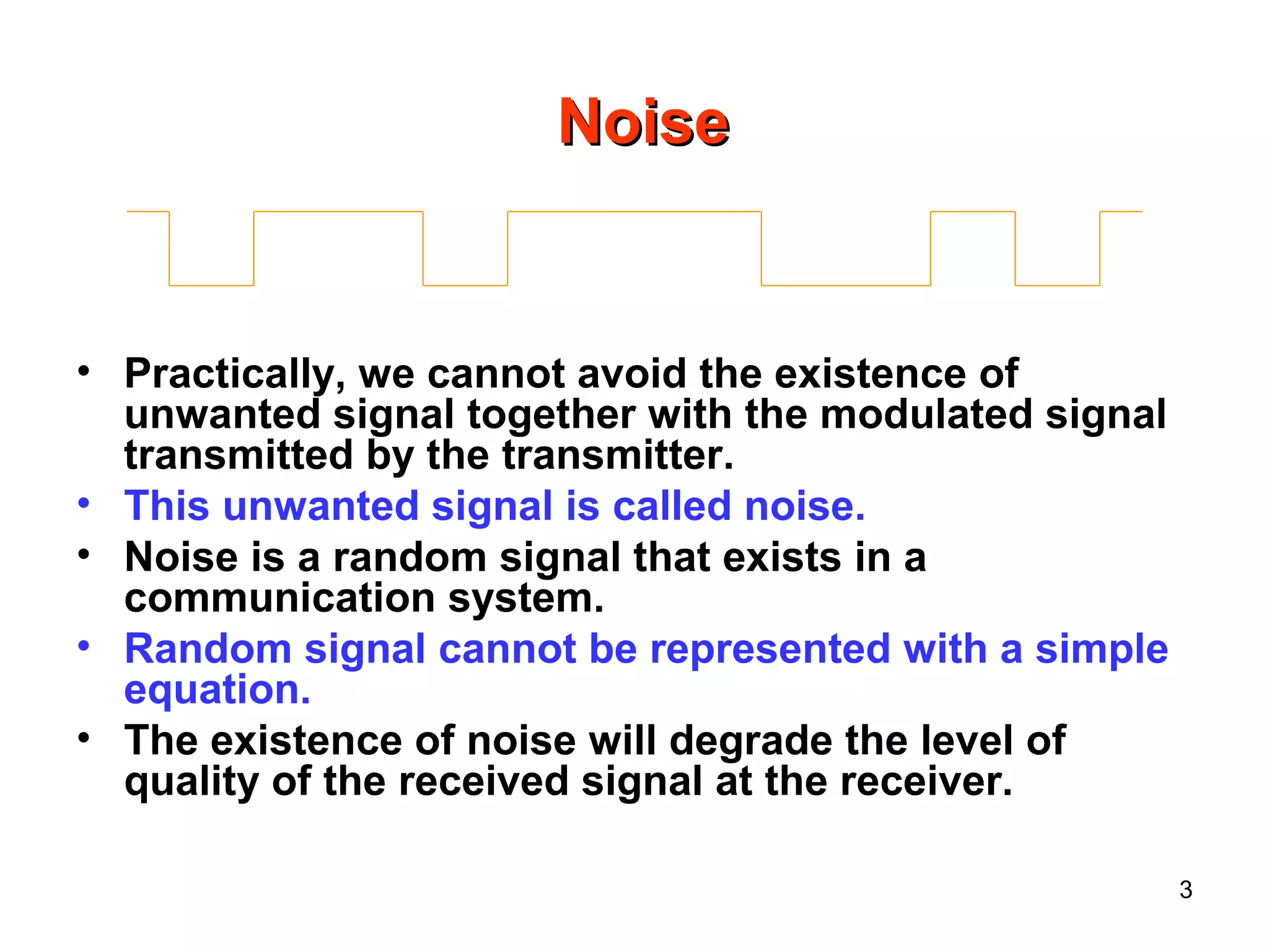
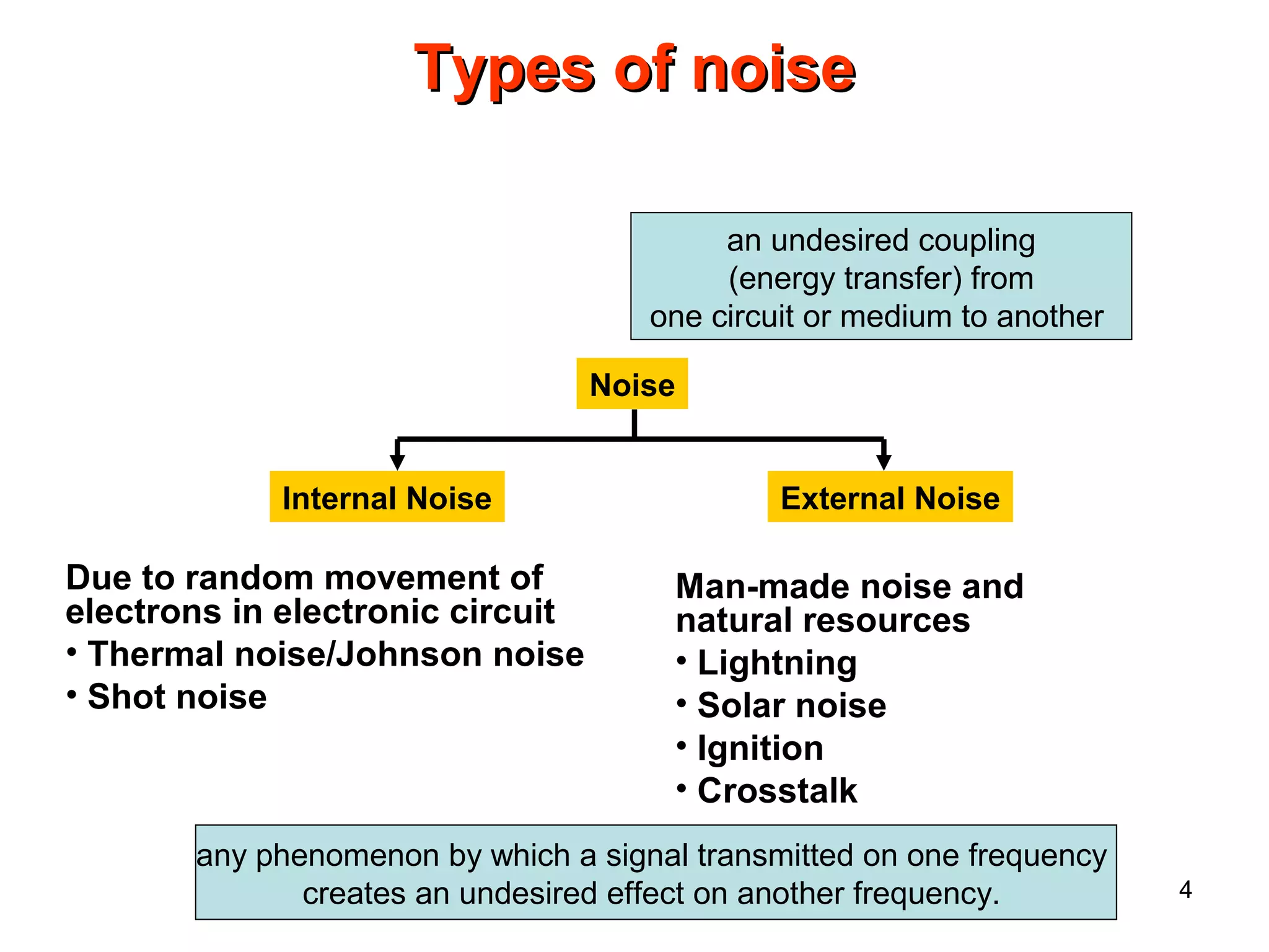
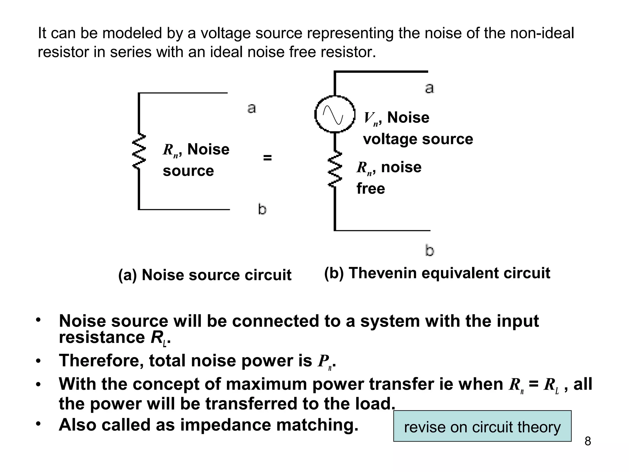
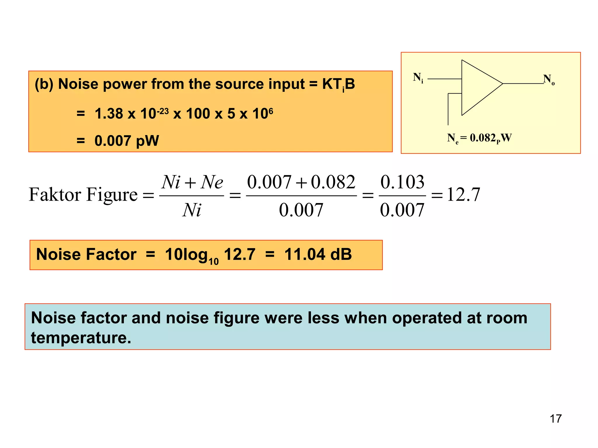
1) Noise exists in all communication systems and degrades signal quality. It is caused by random movement of electrons and can be internal or external.
2) Thermal noise, also known as Johnson noise, is generated by thermal agitation of electrons in conductors. It is proportional to temperature and bandwidth.
3) Noise figure and noise temperature are used to measure the degradation of signal to noise ratio caused by components in a communication system. Lower noise figure and temperature indicate less degradation.
Sampling is a Simple method to convert analog signal into discrete Signal by using any one of its three methods
if the sampling frequency is twice or greater than twice then sampled signal can be convert back into analog signal easily......
Hello everyone. This is a short presentation on path loss and shadowing. I have not covered all the topics but a brief idea is given on path loss and wireless channel propagation models.
Hope you find it useful.
Thanks
This presentation will explain about the need for modulation in communication system. We made this presentation as our group assignment in Analog and Digital Communication System course in MIIT.
RF Carrier oscillator
To generate the carrier signal.
Usually a crystal-controlled oscillator is used.
Buffer amplifier
Low gain, high input impedance linear amplifier.
To isolate the oscillator from the high power amplifiers.
Modulator : can use either emitter collector modulation
Intermediate and final power amplifiers (pull-push modulators)
Required with low-level transmitters to maintain symmetry in the AM envelope
Coupling network
Matches output impedance of the final amplifier to the transmission line/antenn
Applications are in low-power, low-capacity systems : wireless intercoms, remote control units, pagers and short-range walkie-talkie
Modulating signal is processed similarly as in low-level transmitter except for the addition of power amplifier
Power amplifier
To provide higher power modulating signal necessary to achieve 100% modulation (carrier power is maximum at the high-level modulation point).
Same circuit as low-level transmitter for carrier oscillator, buffer and driver but with addition of power amplifier
Introduction to basics of wireless networks such as
• Radio waves & wireless signal encoding techniques
• Wireless networking issues & constraints
• Wireless internetworking devices
Base band transmission
*Wave form representation of binary digits
*PCM, DPCM, DM, ADM systems
*Detection of signals in Gaussian noise
*Matched filter - Application of matched filter
*Error probability performance of binary signaling
*Multilevel base band transmission
*Inter symbol interference
*Eye pattern
*Companding
*A law and μ law
*Correlation receiver
The Presentation is as per the syllabus of the subject ”Digital Communication” of B.E. VIth Semester of Sant Gadge Baba Amravati University, Maharashtra, India
Contents are
Digital Communication System
Line Coding
Scrambling
Optical Fiber Communication Part 3 Optical Digital ReceiverMadhumita Tamhane
Current generated by photodetector is very weak and is adversely effected by random noises associated with photo detection process. When amplified, this signal further gets corrupted by amplifiers. Noise considerations are thus important in designing optical receivers.
Most meaningful criteria for measuring performance of a digital communication system is average error probability, and in analog system, it is peak signal to rms noise ratio. ...
This presentation covers types of noise in communication system, noise modelling, thermal noise, shot noise, experimental determination of noise figure, noise figure, friss formula with numerical.
Abstract: A communications system consisting of switching centers and their interconnecting media. (188). Part of
a communication system organized to temporarily associate functional units, transmission channels or
telecommunication circuits for the purpose of providing a desired telecommunication facility.
Note: Examples of NATO-owned switching system are IVSN and TARE. Switching centers receives the control
signals messages or conversation and forward to the required destination, after necessary modification (link
amplification) if necessary. A switching system is a collection of switching elements arranged and controlled in
such a way as to sleep a communication path between any two distant points. Technically, the design for telephone
switching center or equipment requirements in a telecommunication system are determined of the traffic intensity
is defined as the product of the celling rate and the average holding time. This paper reveals about the information
about the switching system and the research about that. Advantages and disadvantages of the switching system
which we are using. A telephone network is composed of a variety of all processing equipment, interstate switching
links and inters office trunks because of the random nature of the call request, the design of equipment switching
links and trunks are quite different . Thus, the traffic ana Switching is an engineering approach on computer networking. Telecommunication networks carry information signals
among entities which are geographically far apart. The entities are involved in the process of information transfer which
may be in the form of a telephone conversation (telephony) or a file transfer between two computers or message between
two terminals etc. Today it is almost turism to state that telecommunication system are the symbol of our informative
age. With the rapidly growing traffic and untargeted growth of cyberspace, telecommunication becomes a fabric of our
life. The future challenges are enormous as we anticipate rapid growth items of new services and no. of users. What
comes with the challenges is a genuine need for more advance methodology supporting analysis and design of
telecommunication architectures.
Switching systems are about how do we move traffic from one part of the network to another and to connect end system
to switches to each other and data arriving to an input port of a switch have to be moved to one or more of output ports.
The communication switching system enables the universal connectivity. The universal connectivity is realized when any
entity is one part of the world can communicate with any other entity is another part of the world. The telecommunication
links and switching were mainly designed for voice communication. With the appropriate attachments and equipments
they can be used to transmit data. Samue
Smart TV Buyer Insights Survey 2024 by 91mobiles.pdf91mobiles
91mobiles recently conducted a Smart TV Buyer Insights Survey in which we asked over 3,000 respondents about the TV they own, aspects they look at on a new TV, and their TV buying preferences.
UiPath Test Automation using UiPath Test Suite series, part 4DianaGray10
Welcome to UiPath Test Automation using UiPath Test Suite series part 4. In this session, we will cover Test Manager overview along with SAP heatmap.
The UiPath Test Manager overview with SAP heatmap webinar offers a concise yet comprehensive exploration of the role of a Test Manager within SAP environments, coupled with the utilization of heatmaps for effective testing strategies.
Participants will gain insights into the responsibilities, challenges, and best practices associated with test management in SAP projects. Additionally, the webinar delves into the significance of heatmaps as a visual aid for identifying testing priorities, areas of risk, and resource allocation within SAP landscapes. Through this session, attendees can expect to enhance their understanding of test management principles while learning practical approaches to optimize testing processes in SAP environments using heatmap visualization techniques
What will you get from this session?
1. Insights into SAP testing best practices
2. Heatmap utilization for testing
3. Optimization of testing processes
4. Demo
Topics covered:
Execution from the test manager
Orchestrator execution result
Defect reporting
SAP heatmap example with demo
Speaker:
Deepak Rai, Automation Practice Lead, Boundaryless Group and UiPath MVP
Slack (or Teams) Automation for Bonterra Impact Management (fka Social Soluti...Jeffrey Haguewood
Sidekick Solutions uses Bonterra Impact Management (fka Social Solutions Apricot) and automation solutions to integrate data for business workflows.
We believe integration and automation are essential to user experience and the promise of efficient work through technology. Automation is the critical ingredient to realizing that full vision. We develop integration products and services for Bonterra Case Management software to support the deployment of automations for a variety of use cases.
This video focuses on the notifications, alerts, and approval requests using Slack for Bonterra Impact Management. The solutions covered in this webinar can also be deployed for Microsoft Teams.
Interested in deploying notification automations for Bonterra Impact Management? Contact us at sales@sidekicksolutionsllc.com to discuss next steps.
"Impact of front-end architecture on development cost", Viktor TurskyiFwdays
I have heard many times that architecture is not important for the front-end. Also, many times I have seen how developers implement features on the front-end just following the standard rules for a framework and think that this is enough to successfully launch the project, and then the project fails. How to prevent this and what approach to choose? I have launched dozens of complex projects and during the talk we will analyze which approaches have worked for me and which have not.
Builder.ai Founder Sachin Dev Duggal's Strategic Approach to Create an Innova...Ramesh Iyer
In today's fast-changing business world, Companies that adapt and embrace new ideas often need help to keep up with the competition. However, fostering a culture of innovation takes much work. It takes vision, leadership and willingness to take risks in the right proportion. Sachin Dev Duggal, co-founder of Builder.ai, has perfected the art of this balance, creating a company culture where creativity and growth are nurtured at each stage.
JMeter webinar - integration with InfluxDB and GrafanaRTTS
Watch this recorded webinar about real-time monitoring of application performance. See how to integrate Apache JMeter, the open-source leader in performance testing, with InfluxDB, the open-source time-series database, and Grafana, the open-source analytics and visualization application.
In this webinar, we will review the benefits of leveraging InfluxDB and Grafana when executing load tests and demonstrate how these tools are used to visualize performance metrics.
Length: 30 minutes
Session Overview
-------------------------------------------
During this webinar, we will cover the following topics while demonstrating the integrations of JMeter, InfluxDB and Grafana:
- What out-of-the-box solutions are available for real-time monitoring JMeter tests?
- What are the benefits of integrating InfluxDB and Grafana into the load testing stack?
- Which features are provided by Grafana?
- Demonstration of InfluxDB and Grafana using a practice web application
To view the webinar recording, go to:
https://www.rttsweb.com/jmeter-integration-webinar
GraphRAG is All You need? LLM & Knowledge GraphGuy Korland
Guy Korland, CEO and Co-founder of FalkorDB, will review two articles on the integration of language models with knowledge graphs.
1. Unifying Large Language Models and Knowledge Graphs: A Roadmap.
https://arxiv.org/abs/2306.08302
2. Microsoft Research's GraphRAG paper and a review paper on various uses of knowledge graphs:
https://www.microsoft.com/en-us/research/blog/graphrag-unlocking-llm-discovery-on-narrative-private-data/
State of ICS and IoT Cyber Threat Landscape Report 2024 previewPrayukth K V
The IoT and OT threat landscape report has been prepared by the Threat Research Team at Sectrio using data from Sectrio, cyber threat intelligence farming facilities spread across over 85 cities around the world. In addition, Sectrio also runs AI-based advanced threat and payload engagement facilities that serve as sinks to attract and engage sophisticated threat actors, and newer malware including new variants and latent threats that are at an earlier stage of development.
The latest edition of the OT/ICS and IoT security Threat Landscape Report 2024 also covers:
State of global ICS asset and network exposure
Sectoral targets and attacks as well as the cost of ransom
Global APT activity, AI usage, actor and tactic profiles, and implications
Rise in volumes of AI-powered cyberattacks
Major cyber events in 2024
Malware and malicious payload trends
Cyberattack types and targets
Vulnerability exploit attempts on CVEs
Attacks on counties – USA
Expansion of bot farms – how, where, and why
In-depth analysis of the cyber threat landscape across North America, South America, Europe, APAC, and the Middle East
Why are attacks on smart factories rising?
Cyber risk predictions
Axis of attacks – Europe
Systemic attacks in the Middle East
Download the full report from here:
https://sectrio.com/resources/ot-threat-landscape-reports/sectrio-releases-ot-ics-and-iot-security-threat-landscape-report-2024/
Software Delivery At the Speed of AI: Inflectra Invests In AI-Powered QualityInflectra
In this insightful webinar, Inflectra explores how artificial intelligence (AI) is transforming software development and testing. Discover how AI-powered tools are revolutionizing every stage of the software development lifecycle (SDLC), from design and prototyping to testing, deployment, and monitoring.
Learn about:
• The Future of Testing: How AI is shifting testing towards verification, analysis, and higher-level skills, while reducing repetitive tasks.
• Test Automation: How AI-powered test case generation, optimization, and self-healing tests are making testing more efficient and effective.
• Visual Testing: Explore the emerging capabilities of AI in visual testing and how it's set to revolutionize UI verification.
• Inflectra's AI Solutions: See demonstrations of Inflectra's cutting-edge AI tools like the ChatGPT plugin and Azure Open AI platform, designed to streamline your testing process.
Whether you're a developer, tester, or QA professional, this webinar will give you valuable insights into how AI is shaping the future of software delivery.
Search and Society: Reimagining Information Access for Radical FuturesBhaskar Mitra
The field of Information retrieval (IR) is currently undergoing a transformative shift, at least partly due to the emerging applications of generative AI to information access. In this talk, we will deliberate on the sociotechnical implications of generative AI for information access. We will argue that there is both a critical necessity and an exciting opportunity for the IR community to re-center our research agendas on societal needs while dismantling the artificial separation between the work on fairness, accountability, transparency, and ethics in IR and the rest of IR research. Instead of adopting a reactionary strategy of trying to mitigate potential social harms from emerging technologies, the community should aim to proactively set the research agenda for the kinds of systems we should build inspired by diverse explicitly stated sociotechnical imaginaries. The sociotechnical imaginaries that underpin the design and development of information access technologies needs to be explicitly articulated, and we need to develop theories of change in context of these diverse perspectives. Our guiding future imaginaries must be informed by other academic fields, such as democratic theory and critical theory, and should be co-developed with social science scholars, legal scholars, civil rights and social justice activists, and artists, among others.
LF Energy Webinar: Electrical Grid Modelling and Simulation Through PowSyBl -...DanBrown980551
Do you want to learn how to model and simulate an electrical network from scratch in under an hour?
Then welcome to this PowSyBl workshop, hosted by Rte, the French Transmission System Operator (TSO)!
During the webinar, you will discover the PowSyBl ecosystem as well as handle and study an electrical network through an interactive Python notebook.
PowSyBl is an open source project hosted by LF Energy, which offers a comprehensive set of features for electrical grid modelling and simulation. Among other advanced features, PowSyBl provides:
- A fully editable and extendable library for grid component modelling;
- Visualization tools to display your network;
- Grid simulation tools, such as power flows, security analyses (with or without remedial actions) and sensitivity analyses;
The framework is mostly written in Java, with a Python binding so that Python developers can access PowSyBl functionalities as well.
What you will learn during the webinar:
- For beginners: discover PowSyBl's functionalities through a quick general presentation and the notebook, without needing any expert coding skills;
- For advanced developers: master the skills to efficiently apply PowSyBl functionalities to your real-world scenarios.
The Art of the Pitch: WordPress Relationships and SalesLaura Byrne
Clients don’t know what they don’t know. What web solutions are right for them? How does WordPress come into the picture? How do you make sure you understand scope and timeline? What do you do if sometime changes?
All these questions and more will be explored as we talk about matching clients’ needs with what your agency offers without pulling teeth or pulling your hair out. Practical tips, and strategies for successful relationship building that leads to closing the deal.
Kubernetes & AI - Beauty and the Beast !?! @KCD Istanbul 2024Tobias Schneck
As AI technology is pushing into IT I was wondering myself, as an “infrastructure container kubernetes guy”, how get this fancy AI technology get managed from an infrastructure operational view? Is it possible to apply our lovely cloud native principals as well? What benefit’s both technologies could bring to each other?
Let me take this questions and provide you a short journey through existing deployment models and use cases for AI software. On practical examples, we discuss what cloud/on-premise strategy we may need for applying it to our own infrastructure to get it to work from an enterprise perspective. I want to give an overview about infrastructure requirements and technologies, what could be beneficial or limiting your AI use cases in an enterprise environment. An interactive Demo will give you some insides, what approaches I got already working for real.
2. 2
IntroductionIntroduction
“How do you want to send data/information to
someone who is far from you?”
“If the information that you want to send is your
voice, how to make sure that what your words
are understood by your friend?”
“What is the source and technology available
surround you that can help?”
3. 3
NoiseNoise
• Practically, we cannot avoid the existence of
unwanted signal together with the modulated signal
transmitted by the transmitter.
• This unwanted signal is called noise.
• Noise is a random signal that exists in a
communication system.
• Random signal cannot be represented with a simple
equation.
• The existence of noise will degrade the level of
quality of the received signal at the receiver.
4. 4
Types of noiseTypes of noise
Noise
Internal Noise External Noise
Due to random movement of
electrons in electronic circuit
• Thermal noise/Johnson noise
• Shot noise
Man-made noise and
natural resources
• Lightning
• Solar noise
• Ignition
• Crosstalk
any phenomenon by which a signal transmitted on one frequency
creates an undesired effect on another frequency.
an undesired coupling
(energy transfer) from
one circuit or medium to another
5. 5
Noise EffectNoise Effect
• Degrade system performance for both analog and
digital systems.
• The receiver cannot understand the sender.
• The receiver cannot function as it should be.
• Reduce the efficiency of communication system.
6. 6
Thermal NoiseThermal Noise
• Johnson–Nyquist noise (thermal noise, Johnson noise, or
Nyquist noise) is the Electronic noise - generated by the
thermal agitation of the charge carriers (the electrons) inside
an electrical conductor in equilibrium, which happens
regardless of any applied voltage.
• Movement of the electrons will forms kinetic energy in the conductor
related to the temperature of the conductor.
• When the temperature increases, the movement of free electrons will
increase and the current flows through the conductor.
• Current flows due to the free electrons will create noise voltage, n(t).
• Noise voltage, n(t) is influenced by the temperature and therefore it is
called thermal noise.
• Also known as Johnson noise or white noise.
7. 7
kTBP
TBP
n
n
=
∝
Watt
where
Pn = noise power (Watt)
k = Boltzmann’s constant (1.38 x 10⁻²³
J/K)
T = Temperature (K)
B = BW spectrum system (Hz)
In 1928, J. B. Johnson have proven that noise power generated is
proportional to the temperature and the BW.
Noise power can be modeled using voltage equivalent circuit (Thevenin
equivalent circuit) or current equivalent circuit (Norton equivalent circuit)
This type of noise was first measured by John B. Johnson at Bell Labs in 1928. He described his
findings to Harry Nyquist, also at Bell Labs, who was able to explain the results.
8. 8
• Noise source will be connected to a system with the input
resistance RL.
• Therefore, total noise power is Pn.
• With the concept of maximum power transfer ie when Rn = RL , all
the power will be transferred to the load.
• Also called as impedance matching.
Rn, Noise
source
Vn, Noise
voltage source
Rn, noise
free
=
(b) Thevenin equivalent circuit(a) Noise source circuit
It can be modeled by a voltage source representing the noise of the non-ideal
resistor in series with an ideal noise free resistor.
revise on circuit theory
9. 9
RL, system input
resistance
Vn, Noise
voltage source
Rn, Noise
free
(c) Thevenin equivalent circuit with the load
VL
RRR Ln ==
R
V
R
V
R
V
P n
n
L
L
4
2 2
2
2
=
==
kTBPP Ln ==2
n
n
Ln
L
L
V
V
RR
R
V
=
+
=
Note: Vn = Vrms
kTBRV
kTBRV
kTB
R
V
n
n
n
4
4
4
2
2
=
=
=
Given
Voltage across RL :
=>
and
=>
voltage divider rule
10. 10
Example 1
One operational amplifier with a frequency range of (18-20) MHz has
input resistance 10 kΩ. Calculate noise voltage at the input if the
amplifier operate at ambient temperature of 270
C.
Vn
2
= 4KTBR
= 4 x 1.38 x 10-23
x (273+ 27) x 2 x 106
x 104
Vn
= 18 µvolt
BW = fh – fl = (20-18) MHz
= 2 MHz
11. 11
How to determine noise level inHow to determine noise level in
communication system?communication system?
• Noise effect can be determined by measuring:
- Signal to Noise Ratio, SNR for analog system
- probability of error or bit error rate, BER for digital
system
• To determine the quality of received signal at the
receiver or an antenna, SNRiis used.
• SNR o is always less than SNRi, due to the facts that
the existence of noise in the receiver itself.
• Another parameters that can be used is Noise
Factor, F and Noise Temperature, Te.
output=receiver
12. 12
Noise CalculationNoise Calculation
• SNR is a ratio of signal power, S to noise power, N.
• Noise Figure, F
• Noise factor, NF
dB
N
S
SNR log10=
dB
NS
NS
FNF
oo
ii
log10
log10
=
=
oo
ii
NS
NS
F = dB
13. 13
Noise calculation in AmplifierNoise calculation in Amplifier
• To simplify the analysis, two types of noise model are used.
• - Amplifier with noise
• - Amplifier without noise
aio NGNN +=
G
Na
Ni No
G
Ni
No
Nai
(a) Amplifier with noise (b) Amplifier without noise
( )aiio NNGN +=
where
G
N
N a
ai = BkTNP iin ==and
input noise, Ni
artificial noise source, Nai
Gain
14. 14
Analysis Amplifier with NoiseAnalysis Amplifier with Noise
io GSS =
( )aii
a
i
aio
NNG
G
N
NG
NGNN
+=
+=
+=
G
Na
Model Amplifier with noise
Ni
So
No
Si
(1)
( )
i
ai
i
aii
aii
i
i
i
o
i
N
N
N
NN
NNG
GS
N
S
SNR
SNR
+=
+
=
+
=
1
i
ai
N
N
F +=1
io SNRSNR <<
(2)
( ) ie TFT 1−=
i
e
T
T
F +=1
Noise Figure: Noise Temperature:
BkT
BkT
F
i
e
+=1
We have:
BkTN ii = BkTN eai =and
=>
(3)
Noise Figure, F
15. 15
Analysis Amplifier Without NoiseAnalysis Amplifier Without Noise
G
Si So
NoNi+Nai
Model Amplifier without noise
( )aiio
io
NNGN
GSS
+=
=
( )
i
ai
i
aii
aii
i
i
i
o
i
N
N
N
NN
NNG
GS
N
S
SNR
SNR
+=
+
=
+
=
1
i
ai
N
N
F +=1
io SNRSNR <<
(2)
( ) ie TFT 1−=
i
e
T
T
F +=1
Noise Figure: Noise Temperature:
BkT
BkT
F
i
e
+=1
We have:
BkTN ii = BkTN eai =and
=>
(3)
(1)
16. 16
Example 2
Noise generated in amplifier of 5 MHz bandwidth is represented by
amplifier input noise power of 0.082 pW. Calculate noise factor and
noise figure if the amplifier was fed with the
(a) source input signal match the temperature of 300 K
(b) source input signal match the temperature of 100 K
No
Ni
Ne = 0.082PW
(a) Noise power from the source input = KTiB
= 1.38 x 10-23
x 300 x 5 x 106
= 0.021 pW
9.4
021.0
103.0
021.0
082.0021.0
FigureNoise ==
+
=
+
=
Ni
NeNi
Noise Factor = 10log10
4.9 = 6.9 dB
Ni
17. 17
(b) Noise power from the source input = KTiB
= 1.38 x 10-23
x 100 x 5 x 106
= 0.007 pW
7.12
007.0
103.0
007.0
082.0007.0
ureFaktor Fig ==
+
=
+
=
Ni
NeNi
Noise Factor = 10log10
12.7 = 11.04 dB
Noise factor and noise figure were less when operated at room
temperature.
No
Ni
Ne = 0.082PW
18. 18
Example 3
An antenna is connected to an amplifier with noise temperature, Te
= 125 o
K,
gain, G = 108
. Given the bandwidth, B = 10 MHz and output receiver noise, No
= 10 µW. Determine the antenna temperature, Ti and noise figure, F of the
receiver.
( )
( )
( )
( )
KT
T
GTTKB
GBKTBKT
GNNN
i
i
ei
ei
eio
o
8623
600
1012510101038.110
=∴
+×××=
+=
+=
+=
−
µ
2.1
600
125
11 =+=+=
i
e
T
T
F or 2.1
8.82
100
==
+
=
i
ei
N
NN
F
Thanks to Samura
(600+125)/600