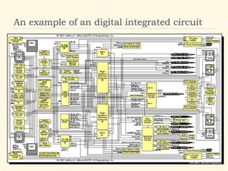
This document provides an overview of integrated circuits and digital techniques including:
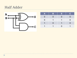
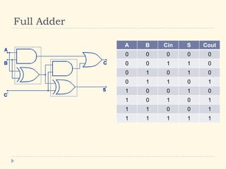
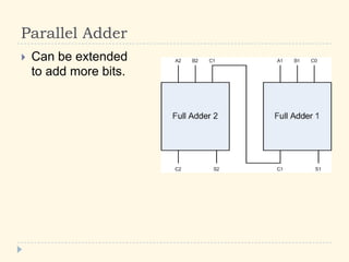
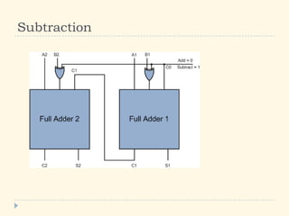
1) Half adders and full adders which are basic building blocks for addition. Parallel adders allow adding more bits. Subtraction is also discussed.
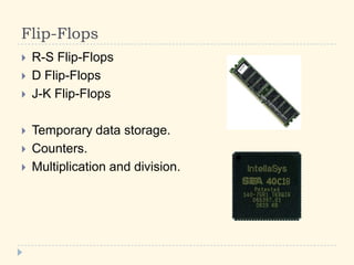
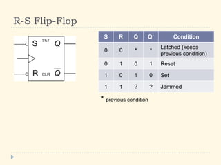
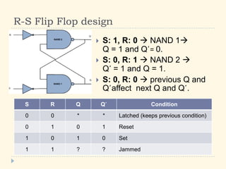
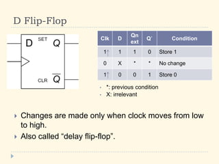
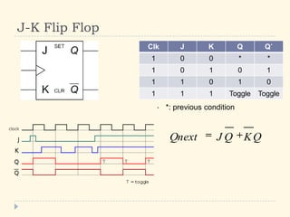
2) Flip-flops like R-S, D, and J-K which are used for temporary data storage, counting, and other operations. Their functions and truth tables are described.
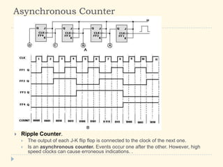
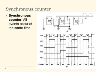
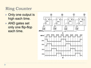
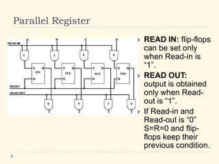
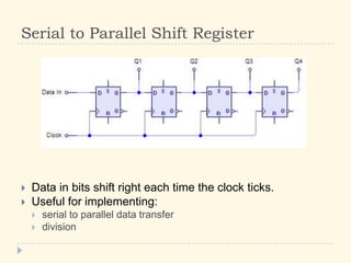
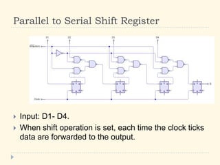
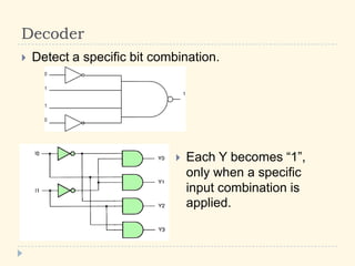
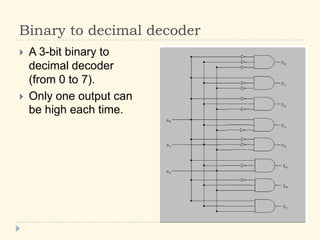
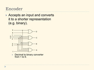
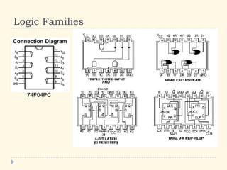
3) Counters, registers, decoders, encoders and other integrated circuits which are constructed using flip-flops and perform operations like serial-parallel conversion.