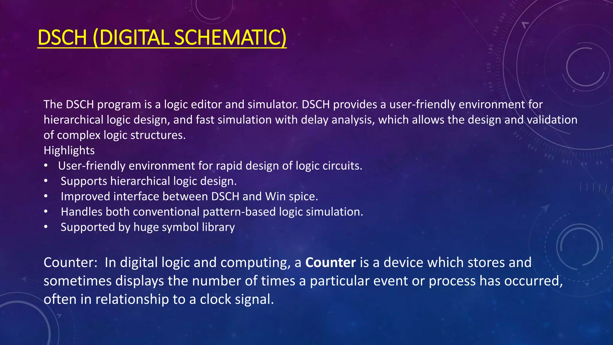
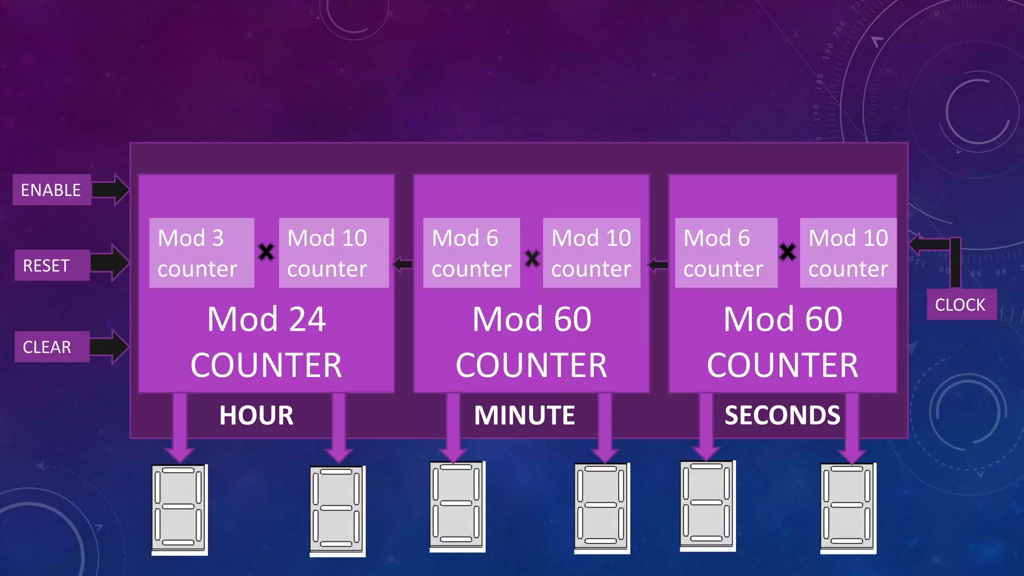
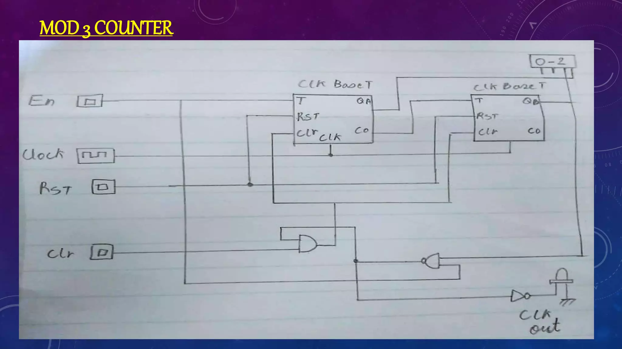
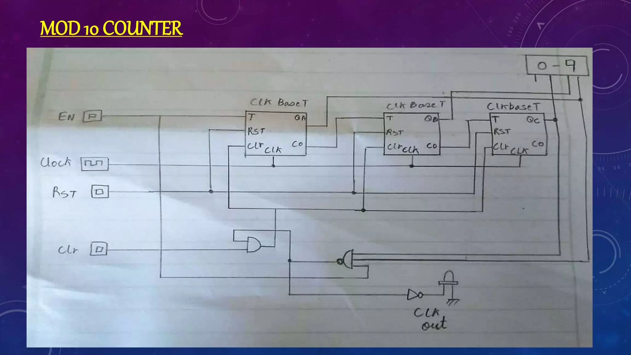
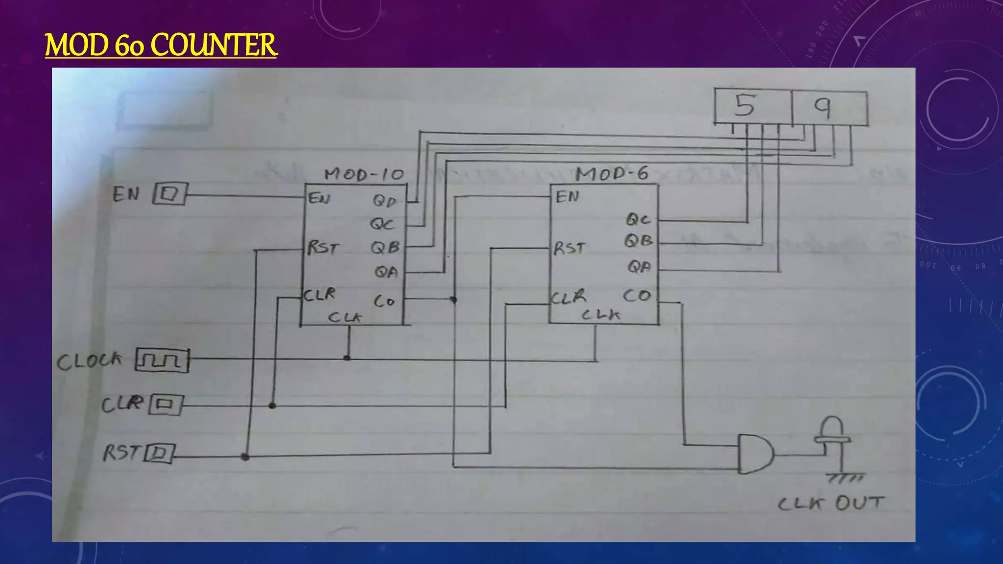
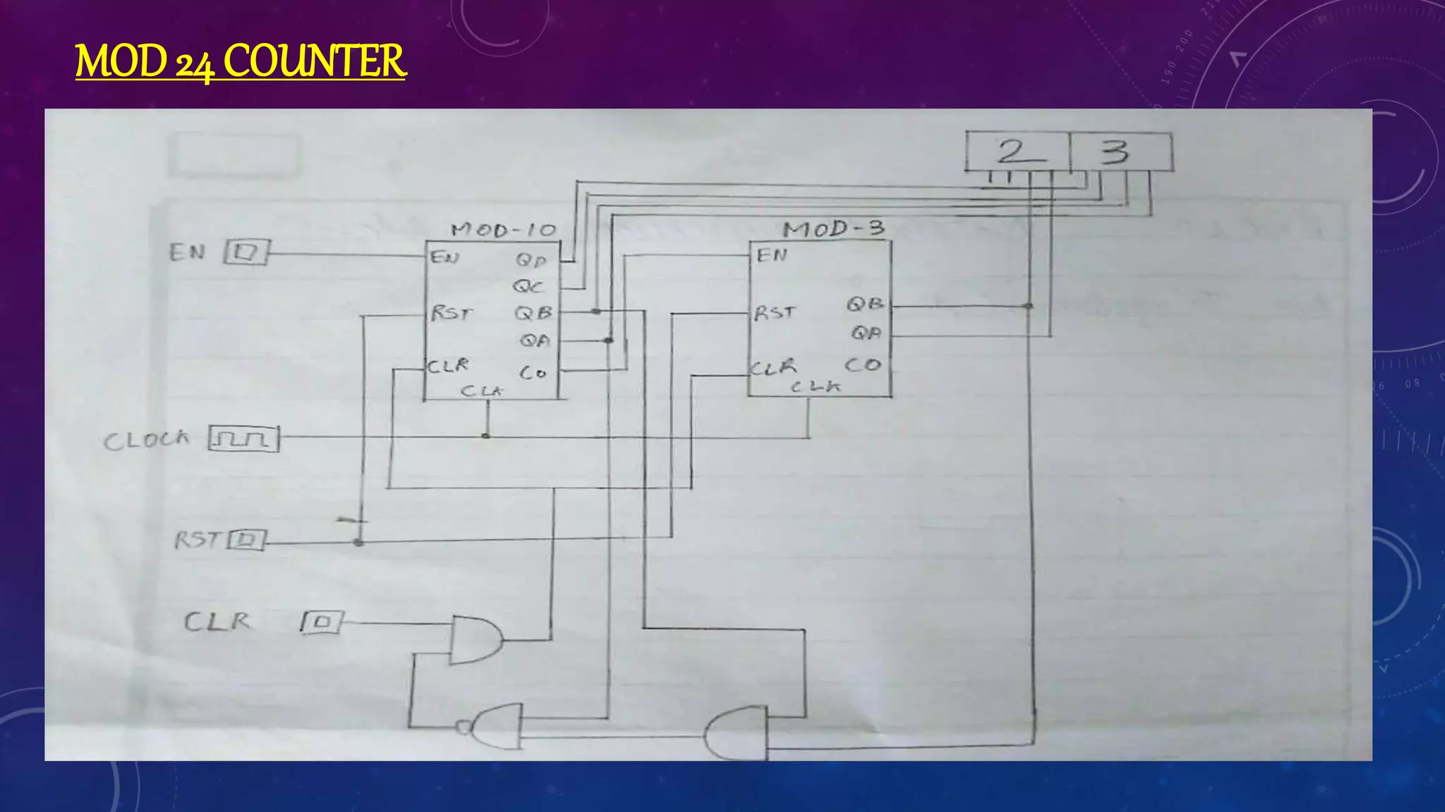
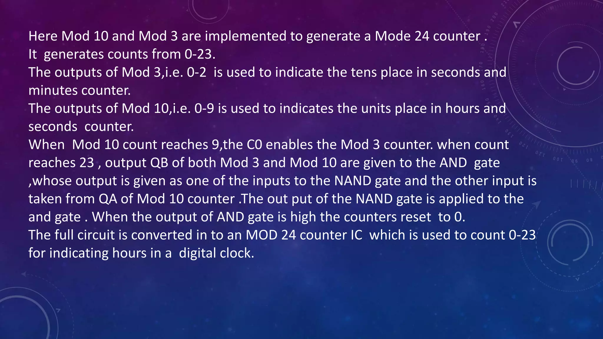
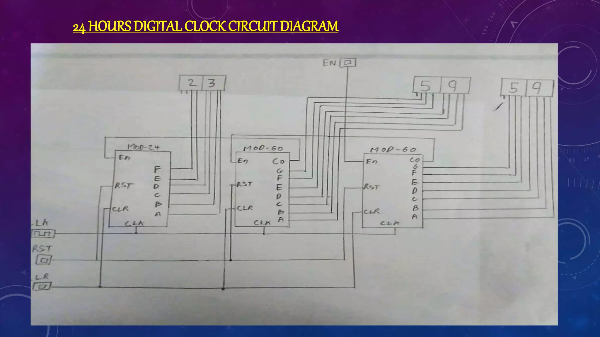
DESIGN OF
COUNTERS
FOR DIGITAL
CLOCK
By GAURAV RAIKAR
DSCH (DIGITAL SCHEMATIC)
The DSCH program is a logic editor and simulator. DSCH provides a user-friendly environment for
hierarchical logic design, and fast simulation with delay analysis, which allows the design and validation
of complex logic structures.
Highlights
• User-friendly environment for rapid design of logic circuits.
• Supports hierarchical logic design.
• Improved interface between DSCH and Win spice.
• Handles both conventional pattern-based logic simulation.
• Supported by huge symbol library
Counter: In digital logic and computing, a Counter is a device which stores and
sometimes displays the number of times a particular event or process has occurred,
often in relationship to a clock signal.
BLOCK
DIAGRAM
Mod 24
COUNTER
Mod 10
counter
Mod 60
COUNTER
Mod 60
COUNTER
Mod 6
counter
Mod 10
counter
Mod 6
counter
Mod 10
counter
Mod 3
counter
CLOCK
ENABLE
RESET
CLEAR
HOUR MINUTE SECONDS
Modulus counters, or simply MOD counters, are defined based on the
number of states that the counter will sequence through before
returning back to its original value.
Mod-N counter will require “N” number of flip-flops connected
together to count a single data bit while providing 2n different output
states, (n is the number of bits).
Here, Mod 3 counter counts up to 0-2 counts (tens place of hour
section of a 24 hour clock resets after 2 ) and mod 6 counter counts up
to 0-5 counts(since tens place of minute section of clock resets after
5). Both mod 3 and mod 6 counters are combined together and
designed to count from 0-23,.i.e. displaying HOURS.
THEORY
Mod 10 counter is used to get a count from 0-9(the ones place of minute and
seconds resets after 9).mod 10 counter is coupled with mod 6 counter to
obtain a mod 60 counter which gives a count from 0-59,i.e. mode 60 counter
is used for displaying Minutes and Sections.
When the seconds reaches count 59 it will enable mode 60(minute).And
when minutes reaches to count 59 it will enable mod 24. After mod 24
reaches 23 the clock will reset to 0 and start the seconds counter again.
Clock triggered Flip-Flop samples the input exactly at the moment when the
clock signal goes up ( rising edge triggered) or down (falling edge triggered).
Here we are implementing negative edge trigger.
Enable input samples the input continuously as long as enable input is
high(1). Enable input can be made low (0) to make the flip-flop stop its
functions.
CIRCUIT
DIAGRAM
CLOCK BASE T FLIPFLOP
Here the D-flip flop is converted to T-flip flop. This designed T or
"toggle" flip-flop changes its output on each falling clock edge.
when you provide a logic-high input to a T input. Output Q
which is initially logic 0, changes to logic high at the falling edge.
The output Q changes from logic high to logic low at the next
falling edge.
Clear clears input to flipflop.
Reset forces the output to zero.
Now this schematic is converted to an clock base T IC.
Clock out is used as input signal for next IC.
MOD3 COUNTER
The En and clear signal is given as a continuous logic high. Initially the
output of both the IC’s is 0. During the first falling edge of the clock the
output QA of the 1st clock base t is high and 2nd clock base t QB is
low(count 1).C0 of the first clock base t enables 2nd clock base t and
during the next falling edge the output QB of the 2nd clock base t is high
and 1st clock base t QA is low(count 2).since we need to count only up to
2 we give the QB to a 2 input nand who receives 1 input from the enable.
The output of the nand gate is connected to the input a 2 input and gate
which receives 1 input from clear. When we obtain count 2 then for the
next falling edge the and gate clears the outputs to 0.
This circuit is converted to an mod 3 IC.
This output is used as tense place in hours counter.
MOD6 COUNTER
Since we need to count up to 5 there fore we need 3 bits, hence we use 3 flip flops.
The En and clear signal is given as a continuous logic high. Initially the output of both the
IC’s is 0. During the first falling edge of the clock the output QA of the 1st clock base t is
high and 2nd and 3rd clock base t QB and QC is low(count 1).C0 of the first clock base t
enables 2nd clock base t and during the next falling edge the output QB of the 2nd clock
base t is high and 1st and 3rd clock base t QA,QC is low(count 2).similarly , each IC’s CO
enables the next IC and we count up to 5. Since we need to count only up to 5 we give the
QA AND QB to a 3 input nand who receives 1 input from the enable. The output of the
nand gate is connected to the input of a 3 input And gate which receives 1 input from
clear. When we obtain count 5 then for the next falling edge the And gate clears the
outputs to 0.
This circuit is converted to an mod 6 IC.
This out put is used as tense place for minutes and seconds counter
MOD10 COUNTER
Since we need to count up to 9 there fore we need 4 bits, hence we use 4 flip flops.
The En and clear signal is given as a continuous logic high.
Initially the output of both the IC’s is 0. During the first falling edge of the clock the
output QA of the 1st clock base t is high and 2nd ,3rd and 4th clock base t QB,QC & QD is
low(count 1).C0 of the first clock base t enables 2nd clock base t and during the next
falling edge the output QB of the 2nd clock base t is high and QA,QC,QD is low(count
2).similarly, each IC’s CO enables the next IC and we count up to 9.since we need to
count only up to 9we give the QA AND QD to a 3 input nand who receives 1 input from
the enable. The output of the nand gate is connected to the input of a 3 input And gate
which receives 1 input from clear. When we obtain count 9 then for the next falling edge
the And gate clears the outputs to 0.
This circuit is converted to an mod 10 IC.
This out put is used as units place for minutes and seconds counter.
MOD60 COUNTER
Here Mod 10 and Mod 6 are implemented to generate a Mode 60 counter .
It generates counts from 0-59.
The outputs of Mod 6,i.e. 0-5 is used to indicate the tens place in seconds and minutes
counter.
The outputs of Mod 10,i.e. 0-9 is used to indicates the units place in hours and seconds
counter. we are using Mod 10 for units place so that we can get 0-9( for count 0-19)
When Mod 10 count reaches 9,the C0 enables the Mod 6 counter .When Count
reaches 59 the counters reset to 0 and the C0 of both the Mod counters are given as
inputs to the AND gate which is given as C0 for further processing .
The full circuit is converted in to an MOD 60 counter IC which is used to count 0-59 for
indicating seconds and minutes in a digital clock.
MOD24 COUNTER
Here Mod 10 and Mod 3 are implemented to generate a Mode 24 counter .
It generates counts from 0-23.
The outputs of Mod 3,i.e. 0-2 is used to indicate the tens place in seconds and
minutes counter.
The outputs of Mod 10,i.e. 0-9 is used to indicates the units place in hours and
seconds counter.
When Mod 10 count reaches 9,the C0 enables the Mod 3 counter. when count
reaches 23 , output QB of both Mod 3 and Mod 10 are given to the AND gate
,whose output is given as one of the inputs to the NAND gate and the other input is
taken from QA of Mod 10 counter .The out put of the NAND gate is applied to the
and gate . When the output of AND gate is high the counters reset to 0.
The full circuit is converted in to an MOD 24 counter IC which is used to count 0-23
for indicating hours in a digital clock.
24 HOURS DIGITAL CLOCKCIRCUITDIAGRAM
When the enable signal is applied to the Mod 60 counter it generates counts form
0-59 ( seconds ). Once the counter reaches 59 the counter resets to 0 and the C0 of
the Mod 60 counter is given as input enable to the 2nd Mod 60 counter and it also
generates counts from 0-59( indicating minutes ).
When the minutes counter reaches 59 the counter resets to 0 and C0 of the 2nd Mod
60 counter is given as input enable to the Mod 24 counter.
The mod 24 counter generates count from 0-24 indicating hours .when the counter
reaches count 23 the counter resets to 0 and the whole process starts all over again.

Digital clock (mod counters)using DSCH (DIGITAL SCHEMATIC) by Gaurav Raikar

  • 1.
  • 2.
    DSCH (DIGITAL SCHEMATIC) TheDSCH program is a logic editor and simulator. DSCH provides a user-friendly environment for hierarchical logic design, and fast simulation with delay analysis, which allows the design and validation of complex logic structures. Highlights • User-friendly environment for rapid design of logic circuits. • Supports hierarchical logic design. • Improved interface between DSCH and Win spice. • Handles both conventional pattern-based logic simulation. • Supported by huge symbol library Counter: In digital logic and computing, a Counter is a device which stores and sometimes displays the number of times a particular event or process has occurred, often in relationship to a clock signal.
  • 3.
  • 4.
    Mod 24 COUNTER Mod 10 counter Mod60 COUNTER Mod 60 COUNTER Mod 6 counter Mod 10 counter Mod 6 counter Mod 10 counter Mod 3 counter CLOCK ENABLE RESET CLEAR HOUR MINUTE SECONDS
  • 5.
    Modulus counters, orsimply MOD counters, are defined based on the number of states that the counter will sequence through before returning back to its original value. Mod-N counter will require “N” number of flip-flops connected together to count a single data bit while providing 2n different output states, (n is the number of bits). Here, Mod 3 counter counts up to 0-2 counts (tens place of hour section of a 24 hour clock resets after 2 ) and mod 6 counter counts up to 0-5 counts(since tens place of minute section of clock resets after 5). Both mod 3 and mod 6 counters are combined together and designed to count from 0-23,.i.e. displaying HOURS. THEORY
  • 6.
    Mod 10 counteris used to get a count from 0-9(the ones place of minute and seconds resets after 9).mod 10 counter is coupled with mod 6 counter to obtain a mod 60 counter which gives a count from 0-59,i.e. mode 60 counter is used for displaying Minutes and Sections. When the seconds reaches count 59 it will enable mode 60(minute).And when minutes reaches to count 59 it will enable mod 24. After mod 24 reaches 23 the clock will reset to 0 and start the seconds counter again. Clock triggered Flip-Flop samples the input exactly at the moment when the clock signal goes up ( rising edge triggered) or down (falling edge triggered). Here we are implementing negative edge trigger. Enable input samples the input continuously as long as enable input is high(1). Enable input can be made low (0) to make the flip-flop stop its functions.
  • 7.
  • 8.
    CLOCK BASE TFLIPFLOP
  • 9.
    Here the D-flipflop is converted to T-flip flop. This designed T or "toggle" flip-flop changes its output on each falling clock edge. when you provide a logic-high input to a T input. Output Q which is initially logic 0, changes to logic high at the falling edge. The output Q changes from logic high to logic low at the next falling edge. Clear clears input to flipflop. Reset forces the output to zero. Now this schematic is converted to an clock base T IC. Clock out is used as input signal for next IC.
  • 10.
  • 11.
    The En andclear signal is given as a continuous logic high. Initially the output of both the IC’s is 0. During the first falling edge of the clock the output QA of the 1st clock base t is high and 2nd clock base t QB is low(count 1).C0 of the first clock base t enables 2nd clock base t and during the next falling edge the output QB of the 2nd clock base t is high and 1st clock base t QA is low(count 2).since we need to count only up to 2 we give the QB to a 2 input nand who receives 1 input from the enable. The output of the nand gate is connected to the input a 2 input and gate which receives 1 input from clear. When we obtain count 2 then for the next falling edge the and gate clears the outputs to 0. This circuit is converted to an mod 3 IC. This output is used as tense place in hours counter.
  • 12.
  • 13.
    Since we needto count up to 5 there fore we need 3 bits, hence we use 3 flip flops. The En and clear signal is given as a continuous logic high. Initially the output of both the IC’s is 0. During the first falling edge of the clock the output QA of the 1st clock base t is high and 2nd and 3rd clock base t QB and QC is low(count 1).C0 of the first clock base t enables 2nd clock base t and during the next falling edge the output QB of the 2nd clock base t is high and 1st and 3rd clock base t QA,QC is low(count 2).similarly , each IC’s CO enables the next IC and we count up to 5. Since we need to count only up to 5 we give the QA AND QB to a 3 input nand who receives 1 input from the enable. The output of the nand gate is connected to the input of a 3 input And gate which receives 1 input from clear. When we obtain count 5 then for the next falling edge the And gate clears the outputs to 0. This circuit is converted to an mod 6 IC. This out put is used as tense place for minutes and seconds counter
  • 14.
  • 15.
    Since we needto count up to 9 there fore we need 4 bits, hence we use 4 flip flops. The En and clear signal is given as a continuous logic high. Initially the output of both the IC’s is 0. During the first falling edge of the clock the output QA of the 1st clock base t is high and 2nd ,3rd and 4th clock base t QB,QC & QD is low(count 1).C0 of the first clock base t enables 2nd clock base t and during the next falling edge the output QB of the 2nd clock base t is high and QA,QC,QD is low(count 2).similarly, each IC’s CO enables the next IC and we count up to 9.since we need to count only up to 9we give the QA AND QD to a 3 input nand who receives 1 input from the enable. The output of the nand gate is connected to the input of a 3 input And gate which receives 1 input from clear. When we obtain count 9 then for the next falling edge the And gate clears the outputs to 0. This circuit is converted to an mod 10 IC. This out put is used as units place for minutes and seconds counter.
  • 16.
  • 17.
    Here Mod 10and Mod 6 are implemented to generate a Mode 60 counter . It generates counts from 0-59. The outputs of Mod 6,i.e. 0-5 is used to indicate the tens place in seconds and minutes counter. The outputs of Mod 10,i.e. 0-9 is used to indicates the units place in hours and seconds counter. we are using Mod 10 for units place so that we can get 0-9( for count 0-19) When Mod 10 count reaches 9,the C0 enables the Mod 6 counter .When Count reaches 59 the counters reset to 0 and the C0 of both the Mod counters are given as inputs to the AND gate which is given as C0 for further processing . The full circuit is converted in to an MOD 60 counter IC which is used to count 0-59 for indicating seconds and minutes in a digital clock.
  • 18.
  • 19.
    Here Mod 10and Mod 3 are implemented to generate a Mode 24 counter . It generates counts from 0-23. The outputs of Mod 3,i.e. 0-2 is used to indicate the tens place in seconds and minutes counter. The outputs of Mod 10,i.e. 0-9 is used to indicates the units place in hours and seconds counter. When Mod 10 count reaches 9,the C0 enables the Mod 3 counter. when count reaches 23 , output QB of both Mod 3 and Mod 10 are given to the AND gate ,whose output is given as one of the inputs to the NAND gate and the other input is taken from QA of Mod 10 counter .The out put of the NAND gate is applied to the and gate . When the output of AND gate is high the counters reset to 0. The full circuit is converted in to an MOD 24 counter IC which is used to count 0-23 for indicating hours in a digital clock.
  • 20.
    24 HOURS DIGITALCLOCKCIRCUITDIAGRAM
  • 21.
    When the enablesignal is applied to the Mod 60 counter it generates counts form 0-59 ( seconds ). Once the counter reaches 59 the counter resets to 0 and the C0 of the Mod 60 counter is given as input enable to the 2nd Mod 60 counter and it also generates counts from 0-59( indicating minutes ). When the minutes counter reaches 59 the counter resets to 0 and C0 of the 2nd Mod 60 counter is given as input enable to the Mod 24 counter. The mod 24 counter generates count from 0-24 indicating hours .when the counter reaches count 23 the counter resets to 0 and the whole process starts all over again.