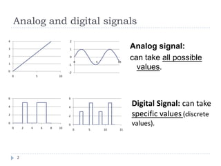
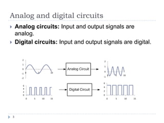
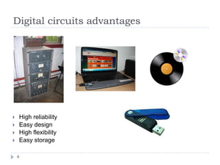
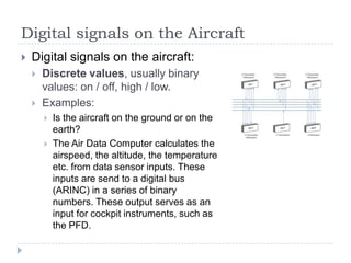
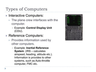
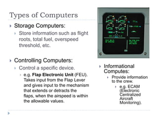
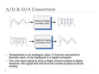
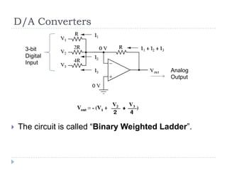
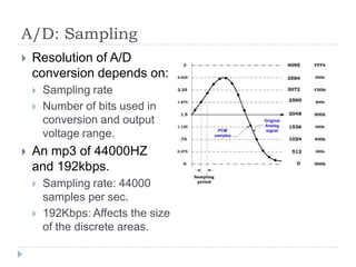
Module 5: Digital Techniques and
Electronic Instrument Systems
5.3 Data Conversion
Analog and digital signals
Analog signal:
can take all possible
values.
-2
-1
0
1
2
0 5 10
Digital Signal: can take
specific values (discrete
values).
0
1
2
3
4
0 5 10
0
2
4
6
0 2 4 6 8 10
0
2
4
6
0 5 10 15
2
Analog and digital circuits
3
 Analog circuits: Input and output signals are
analog.
 Digital circuits: Input and output signals are digital.
-2
-1
0
1
2
0 5 10
-1
0
1
2
0 5 10
0
2
4
6
0 5 10 15
0
2
4
6
0 5 10 15
Digital circuits advantages
4
 High reliability
 Easy design
 High flexibility
 Easy storage
Digital signals on the Aircraft
 Digital signals on the aircraft:
 Discrete values, usually binary
values: on / off, high / low.
 Examples:
 Is the aircraft on the ground or on the
earth?
 The Air Data Computer calculates the
airspeed, the altitude, the temperature
etc. from data sensor inputs. These
inputs are send to a digital bus
(ARINC) in a series of binary
numbers. These output serves as an
input for cockpit instruments, such as
the PFD.
Types of Computers
 Interactive Computers:
 The plane crew interfaces with the
computer.
 Example: Control Display Unit
(CDU).
 Reference Computers:
 Provides information used by
other computers.
 Example: Inertial Reference
System. (IRS – calculates
airspeed, heading, attitude etc.).
Information is provides to other
systems, such as Auto-throttle
computer, FMC etc.
Types of Computers
 Storage Computers:
 Store information such as flight
roots, total fuel, overspeed
threshold, etc.
 Controlling Computers:
 Control a specific device.
 e.g. Flap Electronic Unit (FEU).
Takes input from the Flap Lever
and gives input to the mechanism
that extends or detracts the
flaps, when the airspeed is within
the allowable values.
 Informational
Computes:
 Provide information
to the crew.
 e.g. ECAM
(Electronic
Centralized
Aircraft
Monitoring).
A/D & D/A Converters
 Temperature is an analogue value. It must be converted to
discrete value, to be displayed in a digital computer.
 The user input signal to drive a flight control surface is digital.
However, the signal that will drive the control surface must be
analog.
D/A Converters
 The circuit is called “Binary Weighted Ladder”.
3-bit
Digital
Input
Analog
Output
A/D: Sampling
 Resolution of A/D
conversion depends on:
 Sampling rate
 Number of bits used in
conversion and output
voltage range.
 An mp3 of 44000HZ
and 192kbps.
 Sampling rate: 44000
samples per sec.
 192Kbps: Affects the size
of the discrete areas.
D/A & A/D Converters Specifications
 Accuracy:
 The actual output vs. the converted output.
 E.g. if the maximum output of the converter is 10V and the
error is ±1%, then the maximum error for any voltage output is
10mV.
 Resolution of A/D converters:
 The number of steps the input is divided into. Is expressed in
power of 2. A 12-bit A/D converter divides the analog signal in
212 steps.
 Sample and Hold A/D converters:
 Freezes the analog input at the moment a new sample is taken.
 Throughput:
 The maximum number of bits “produced” or “consumed” per
second (the bit rate).

5.3 Data conversion

  • 1.
    Module 5: DigitalTechniques and Electronic Instrument Systems 5.3 Data Conversion
  • 2.
    Analog and digitalsignals Analog signal: can take all possible values. -2 -1 0 1 2 0 5 10 Digital Signal: can take specific values (discrete values). 0 1 2 3 4 0 5 10 0 2 4 6 0 2 4 6 8 10 0 2 4 6 0 5 10 15 2
  • 3.
    Analog and digitalcircuits 3  Analog circuits: Input and output signals are analog.  Digital circuits: Input and output signals are digital. -2 -1 0 1 2 0 5 10 -1 0 1 2 0 5 10 0 2 4 6 0 5 10 15 0 2 4 6 0 5 10 15
  • 4.
    Digital circuits advantages 4 High reliability  Easy design  High flexibility  Easy storage
  • 5.
    Digital signals onthe Aircraft  Digital signals on the aircraft:  Discrete values, usually binary values: on / off, high / low.  Examples:  Is the aircraft on the ground or on the earth?  The Air Data Computer calculates the airspeed, the altitude, the temperature etc. from data sensor inputs. These inputs are send to a digital bus (ARINC) in a series of binary numbers. These output serves as an input for cockpit instruments, such as the PFD.
  • 6.
    Types of Computers Interactive Computers:  The plane crew interfaces with the computer.  Example: Control Display Unit (CDU).  Reference Computers:  Provides information used by other computers.  Example: Inertial Reference System. (IRS – calculates airspeed, heading, attitude etc.). Information is provides to other systems, such as Auto-throttle computer, FMC etc.
  • 7.
    Types of Computers Storage Computers:  Store information such as flight roots, total fuel, overspeed threshold, etc.  Controlling Computers:  Control a specific device.  e.g. Flap Electronic Unit (FEU). Takes input from the Flap Lever and gives input to the mechanism that extends or detracts the flaps, when the airspeed is within the allowable values.  Informational Computes:  Provide information to the crew.  e.g. ECAM (Electronic Centralized Aircraft Monitoring).
  • 8.
    A/D & D/AConverters  Temperature is an analogue value. It must be converted to discrete value, to be displayed in a digital computer.  The user input signal to drive a flight control surface is digital. However, the signal that will drive the control surface must be analog.
  • 9.
    D/A Converters  Thecircuit is called “Binary Weighted Ladder”. 3-bit Digital Input Analog Output
  • 10.
    A/D: Sampling  Resolutionof A/D conversion depends on:  Sampling rate  Number of bits used in conversion and output voltage range.  An mp3 of 44000HZ and 192kbps.  Sampling rate: 44000 samples per sec.  192Kbps: Affects the size of the discrete areas.
  • 11.
    D/A & A/DConverters Specifications  Accuracy:  The actual output vs. the converted output.  E.g. if the maximum output of the converter is 10V and the error is ±1%, then the maximum error for any voltage output is 10mV.  Resolution of A/D converters:  The number of steps the input is divided into. Is expressed in power of 2. A 12-bit A/D converter divides the analog signal in 212 steps.  Sample and Hold A/D converters:  Freezes the analog input at the moment a new sample is taken.  Throughput:  The maximum number of bits “produced” or “consumed” per second (the bit rate).

Editor's Notes

  • #3 Αναλογικά σήματα που υπάρχουν στη φύση:Το φως του ήλιου κατά τη διάρκεια της ημέρας Η θερμοκρασία κατά τη διάρκεια της ημέρας Ο ήχος
  • #4 Συσκευές με αναλογικά κυκλώματα:Η κουζίνα (εναλλασσόμενο ρεύμα – θερμοκρασία του ηλεκτρικού ματιού)Ηλεκτρικό καλοριφέρΠίνακας της ΔΕΗΗχεία
  • #5  Ευελιξία: Τοίδιο κύκλωμα με διαφορετικό software κάνει άλλα πράγματα Κατανάλωση ενέργειας + μεγαλύτερη ταχύτητα + μέγεθος  εύκολη σχεδίαση (βελτιώνονται οι τεχνολογίες κατασκευής και τα σχεδιάζουν σε μικρότερη κλίμακα, έτσι ώστε να είναι πιο γρήγορα και να καταναλώνουν μικρότερη ενέργεια) Αξιοπιστία: θόρυβος Αποθήκευση: Στο αναλογικό ο θόρυβος θα καταστρέψει τα δεδομένα.