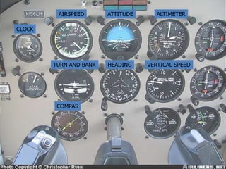
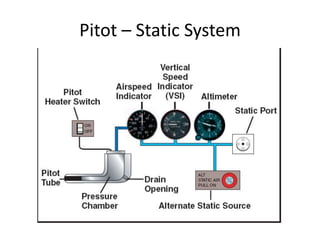
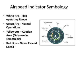
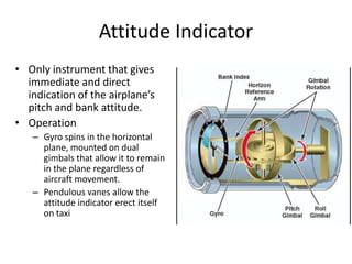
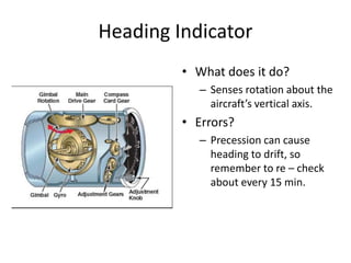
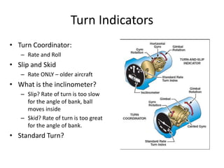
Aircraft Instruments
5.1 ELECTRONIC INSTRUMENT SYSTEM


             www.part66.blogspot.com
AIRSPEED       ATTITUDE      ALTIMETER

CLOCK


        TURN AND BANK   HEADING    VERTICAL SPEED


         COMPAS
Pitot – Static System
Airspeed Indicator Symbology
• White Arc – Flap
  operating Range
• Green Arc – Normal
  Operations
• Yellow Arc – Caution
  Area (Only use in
  smooth air)
• Red Line – Never Exceed
  Speed
Airspeed Indicator
• Uses ram air from the pitot tube as well as static air.
• Ram air pushes against a diaphragm inside the airspeed
  indicator, which will then be able to expand or contract
  accordingly. This movement of the diaphragm is then translated
  into needle movement.
Altimeter
Altimeter
• Static Input Only
• Manufacturer seals the
  aneroid wafer(s) at a
  specific pressure. As the
  static pressure fills in the
  area around these sealed
  wafers, they will be able
  to contract or expand
  accordingly
Altimeter Operation
Air moves out
                       9 0 1
                   8           2
                   7           3
                       6 5 4

               Wafers expand
                       9 0 1
                   8           2
                   7           3
                       6 5 4


Air moves in
                       9 0 1
                   8           2
                   7           3
                       6 5 4

               Wafers contract
High to Low, Look out Below!
Vertical Speed Indicator


              • Rate of climb and descent
• Trend will show immediate indication of an increase in
          the airplanes rate of climb or descent
      • Rate shows a stabilized change in altitude
Vertical Speed Indicator
• Static air enters both the
  diaphragm and the area
  around it. However, the air in
  the diaphragm is constantly
  updated while the air outside
  of it is very slowly allowed to
  escape through a calibrated
  leak. The instrument
  measures the difference in
  these two pressures (the air
  where you where v. where
  you are)
Pitot – Static Summary
• While the Altimeter, VSI and airspeed indicator all
  use Static air, only the airspeed indicator uses Pitot
• If you notice all of your pitot static instruments are
  giving conflicting information, try turning using the
  alternate air source
• If only your airspeed indicator is not working
  properly, try turning on pitot heat
Gyro Instruments
Gyroscopic Principles
• Rigidity in Space
   – A wheel with a heavily
     weighted rim spun rapidly
     tends to remain fixed in the
     plane in which it is spinning
   – The wheel is mounted on a set
     of gimbals so that the gyro is
     able to rotate freely in any
     plane
   – As the gimbals’ base tilts and
     twists, the gyro remains
     spinning in its original plane
   – Allows a gyroscope to measure
     changes in the attitude or
     direction of an airplane
Precession
• What is precession?
   – When an outside force tries to
     tilt a spinning gryo, the gyro
     responds as if the force had
     been applied at a point 90
     degrees in the direction of
     rotation
• Precession side – effects?
   – Friction in gimbals and
     bearings may cause a slow
     drifting in the heading indicator
     and occasional small errors in
     the attitude indicator
Vacuum Instruments
Attitude Indicator
• Only instrument that gives
  immediate and direct
  indication of the airplane’s
  pitch and bank attitude.
• Operation
   – Gyro spins in the horizontal
     plane, mounted on dual
     gimbals that allow it to remain
     in the plane regardless of
     aircraft movement.
   – Pendulous vanes allow the
     attitude indicator erect itself
     on taxi
Heading Indicator
         • What does it do?
            – Senses rotation about the
              aircraft’s vertical axis.
         • Errors?
            – Precession can cause
              heading to drift, so
              remember to re – check
              about every 15 min.
Turn Indicators
• Turn Coordinator:
   – Rate and Roll
• Slip and Skid
   – Rate ONLY – older aircraft
• What is the inclinometer?
   – Slip? Rate of turn is too slow
     for the angle of bank, ball
     moves inside
   – Skid? Rate of turn is too great
     for the angle of bank.
• Standard Turn?
Gyro Instruments Summary
• The gyroscopic instruments incorporate two
  concepts, Rigidity in Space and precession
• The turn coordinator is powered by the
  electrical system rather than the vacuum
  system so that in case of a failure, the pilot
  will always have a way to reference flight
  attitude.
Compass
• Bar Magnet aligns itself
  with the magnetic field
Compass Errors
• Variation: Difference between the true and
  magnetic poles. Use correction indicated on
  sectional
Compass Errors
• Deviation: Compass error due to disturbances
  in magnetic field de to metals and electrical
  accessories in the airplane. Use deviation card
  in airplane to correct.
Compass Errors
• Magnetic Dip: Bar magnet contained in
  compass is pulled by the earth’s magnetic
  field, it tends to point north and somewhat
  downward. Greatest near the poles
Compass Errors
• Acceleration Error: Occurs when accelerating
  or decelerating on an easterly or westerly
  heading. As you accelerate, inertia causes the
  compass weight on the south end of magnetic
  to lag and turn the compass toward north. As
  you decelerate, inertia causes weight to move
  ahead, moves the compass toward a southerly
  heading.
Compass Errors
• Turning Error: Most pronounced when turning
  to or from headings of north or south.
• When you begin a turn from a heading of
  north, the compass initially indicates a turn to
  the opposite direction. When the turn is
  established, the compass begins to turn in the
  correct direction, but it lags behind the actual
  heading.

EASA PART 66 MODULE 5.1 : ELECTRONIC INSTRUMENT SYSTEMS

  • 1.
    Aircraft Instruments 5.1 ELECTRONICINSTRUMENT SYSTEM www.part66.blogspot.com
  • 2.
    AIRSPEED ATTITUDE ALTIMETER CLOCK TURN AND BANK HEADING VERTICAL SPEED COMPAS
  • 3.
  • 4.
    Airspeed Indicator Symbology •White Arc – Flap operating Range • Green Arc – Normal Operations • Yellow Arc – Caution Area (Only use in smooth air) • Red Line – Never Exceed Speed
  • 5.
    Airspeed Indicator • Usesram air from the pitot tube as well as static air. • Ram air pushes against a diaphragm inside the airspeed indicator, which will then be able to expand or contract accordingly. This movement of the diaphragm is then translated into needle movement.
  • 6.
  • 7.
    Altimeter • Static InputOnly • Manufacturer seals the aneroid wafer(s) at a specific pressure. As the static pressure fills in the area around these sealed wafers, they will be able to contract or expand accordingly
  • 8.
    Altimeter Operation Air movesout 9 0 1 8 2 7 3 6 5 4 Wafers expand 9 0 1 8 2 7 3 6 5 4 Air moves in 9 0 1 8 2 7 3 6 5 4 Wafers contract
  • 9.
    High to Low,Look out Below!
  • 10.
    Vertical Speed Indicator • Rate of climb and descent • Trend will show immediate indication of an increase in the airplanes rate of climb or descent • Rate shows a stabilized change in altitude
  • 11.
    Vertical Speed Indicator •Static air enters both the diaphragm and the area around it. However, the air in the diaphragm is constantly updated while the air outside of it is very slowly allowed to escape through a calibrated leak. The instrument measures the difference in these two pressures (the air where you where v. where you are)
  • 12.
    Pitot – StaticSummary • While the Altimeter, VSI and airspeed indicator all use Static air, only the airspeed indicator uses Pitot • If you notice all of your pitot static instruments are giving conflicting information, try turning using the alternate air source • If only your airspeed indicator is not working properly, try turning on pitot heat
  • 13.
  • 14.
    Gyroscopic Principles • Rigidityin Space – A wheel with a heavily weighted rim spun rapidly tends to remain fixed in the plane in which it is spinning – The wheel is mounted on a set of gimbals so that the gyro is able to rotate freely in any plane – As the gimbals’ base tilts and twists, the gyro remains spinning in its original plane – Allows a gyroscope to measure changes in the attitude or direction of an airplane
  • 15.
    Precession • What isprecession? – When an outside force tries to tilt a spinning gryo, the gyro responds as if the force had been applied at a point 90 degrees in the direction of rotation • Precession side – effects? – Friction in gimbals and bearings may cause a slow drifting in the heading indicator and occasional small errors in the attitude indicator
  • 16.
  • 17.
    Attitude Indicator • Onlyinstrument that gives immediate and direct indication of the airplane’s pitch and bank attitude. • Operation – Gyro spins in the horizontal plane, mounted on dual gimbals that allow it to remain in the plane regardless of aircraft movement. – Pendulous vanes allow the attitude indicator erect itself on taxi
  • 18.
    Heading Indicator • What does it do? – Senses rotation about the aircraft’s vertical axis. • Errors? – Precession can cause heading to drift, so remember to re – check about every 15 min.
  • 19.
    Turn Indicators • TurnCoordinator: – Rate and Roll • Slip and Skid – Rate ONLY – older aircraft • What is the inclinometer? – Slip? Rate of turn is too slow for the angle of bank, ball moves inside – Skid? Rate of turn is too great for the angle of bank. • Standard Turn?
  • 20.
    Gyro Instruments Summary •The gyroscopic instruments incorporate two concepts, Rigidity in Space and precession • The turn coordinator is powered by the electrical system rather than the vacuum system so that in case of a failure, the pilot will always have a way to reference flight attitude.
  • 21.
    Compass • Bar Magnetaligns itself with the magnetic field
  • 22.
    Compass Errors • Variation:Difference between the true and magnetic poles. Use correction indicated on sectional
  • 23.
    Compass Errors • Deviation:Compass error due to disturbances in magnetic field de to metals and electrical accessories in the airplane. Use deviation card in airplane to correct.
  • 24.
    Compass Errors • MagneticDip: Bar magnet contained in compass is pulled by the earth’s magnetic field, it tends to point north and somewhat downward. Greatest near the poles
  • 25.
    Compass Errors • AccelerationError: Occurs when accelerating or decelerating on an easterly or westerly heading. As you accelerate, inertia causes the compass weight on the south end of magnetic to lag and turn the compass toward north. As you decelerate, inertia causes weight to move ahead, moves the compass toward a southerly heading.
  • 26.
    Compass Errors • TurningError: Most pronounced when turning to or from headings of north or south. • When you begin a turn from a heading of north, the compass initially indicates a turn to the opposite direction. When the turn is established, the compass begins to turn in the correct direction, but it lags behind the actual heading.