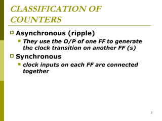
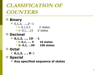
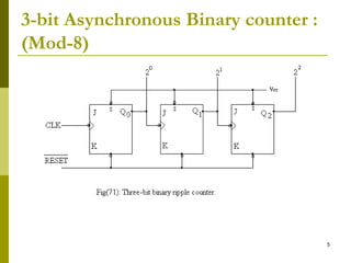
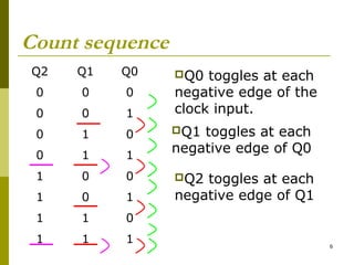
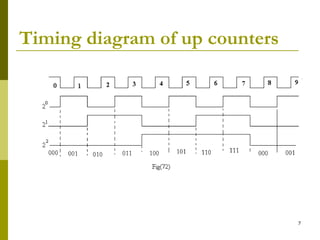
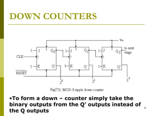
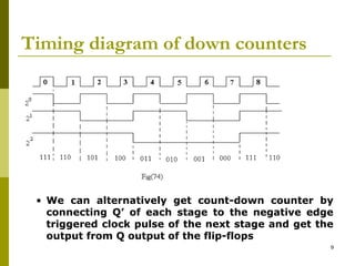
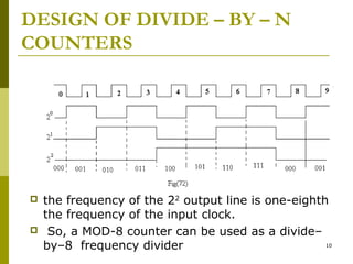
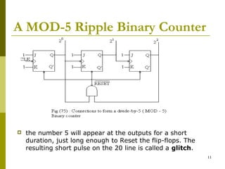
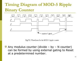
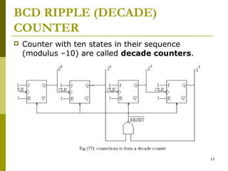
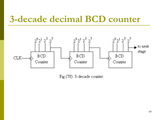
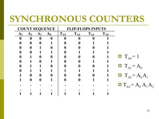
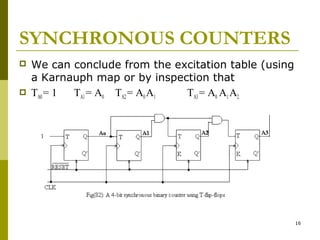
CHAPTER 8
Counter Circuits

1
CLASSIFICATION OF
COUNTERS


Asynchronous (ripple)




They use the O/P of one FF to generate
the clock transition on another FF (s)

Synchronous


clock inputs on each FF are connected
together

2
CLASSIFICATION OF
COUNTERS


Binary


0,1,2, ….,2n –1





0,1,2, …, 10n ‑ 1



i- 0,1, …. 9
ii- 0,1, …99

10 states
100 states

Octal




22 states
24 states

Decimal




i- 0,1,2,3
ii- 0,1,…,15

0,1,2, .. , 8n-1

Special


Any specified sequence sf states
3
CLASSIFICATION OF
COUNTERS
up
 down
 up/down


4
3-bit Asynchronous Binary counter :
(Mod-8)

5
Count sequence
Q2

Q1

Q0

0

0

0

0

0

1

toggles at each
negative edge of the
clock input.

0

1

0

Q1

0

1

1

1

0

0

1

0

1

1

1

0

1

1

1

Q0

toggles at each
negative edge of Q0
Q2

toggles at each
negative edge of Q1

6
Timing diagram of up counters

7
DOWN COUNTERS

•To form a down – counter simply take the
binary outputs from the Q’ outputs instead of
the Q outputs

8
Timing diagram of down counters

• We can alternatively get count-down counter by
connecting Q’ of each stage to the negative edge
triggered clock pulse of the next stage and get the
output from Q output of the flip-flops
9
DESIGN OF DIVIDE – BY – N
COUNTERS





the frequency of the 22 output line is one-eighth
the frequency of the input clock.
So, a MOD-8 counter can be used as a divide–
10
by–8 frequency divider
A MOD-5 Ripple Binary Counter



the number 5 will appear at the outputs for a short
duration, just long enough to Reset the flip-flops. The
resulting short pulse on the 20 line is called a glitch.
11
Timing Diagram of MOD-5 Ripple
Binary Counter



Any modulus counter (divide – by – N counter)
can be formed by using external gating to Reset
at a predetermined number.
12
BCD RIPPLE (DECADE)
COUNTER


Counter with ten states in their sequence
(modulus –10) are called decade counters.

13
3-decade decimal BCD counter

14
SYNCHRONOUS COUNTERS
COUNT SEQUENCE
A3 A2 A1 A0
0
0
0
0
0
0
0
1
0
0
1
0
0
0
1
1
0
1
0
0
0
1
0
1
0
1
1
0
0
1
1
1
1
0
0
0
1
0
0
1
.
.
.
.
.
.
.
.
1
1
1
1

FLIP-FLOPS INPUTS
TA3
TA2
TA1
TA0
0
0
0
1
0
0
1
1
0
0
0
1
0
1
1
1
0
0
0
1
0
0
1
1
0
0
0
1
1
1
1
1
0
0
0
1
0
0
1
1
.
.
.
.
.
.
.
.
1
1
1
1



TA0 = 1



TA1 = A0



TA2 = A0 A1



TA3 = A0 A1 A2

15
SYNCHRONOUS COUNTERS




We can conclude from the excitation table (using
a Karnauph map or by inspection that
TA0 = 1
TA1 = A0 TA2 = A0 A1
TA3 = A0 A1 A2

16
Synchronous Counter Using J-K

17
SYNCHRONOUS BINARY DOWNCOUNTER
• The only change is that the outputs are used as inputs to
the T (or J–K) input of the next flip-flop.

18
UP/DOWN SYNCHRONOUS
COUNTERS

19

Logic Design - Chapter 8: counters