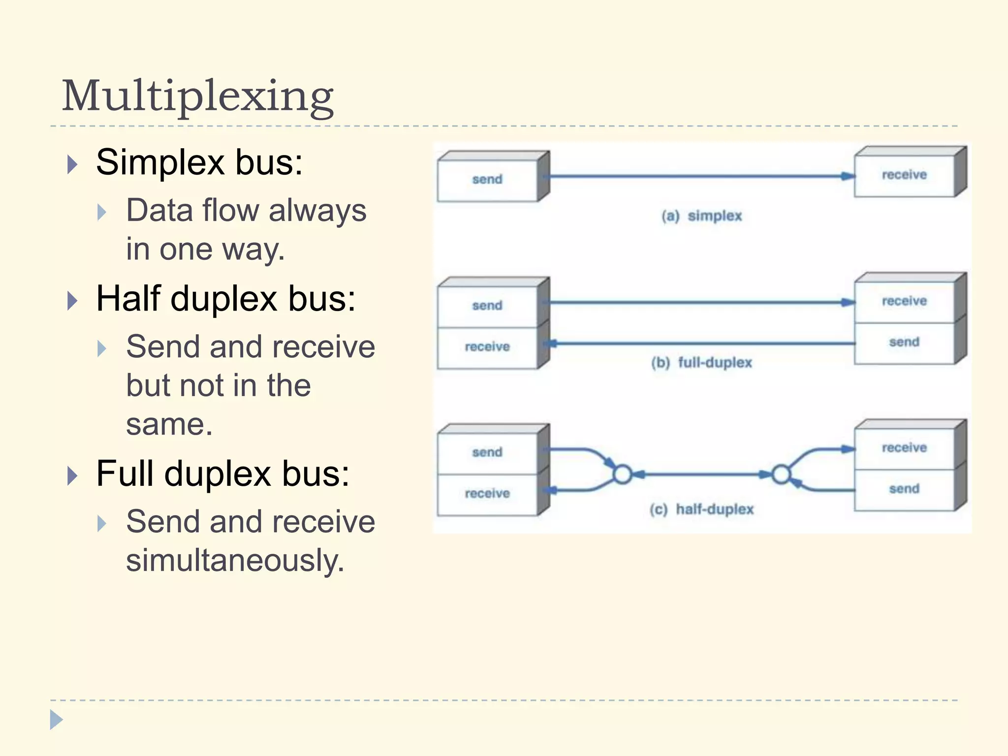
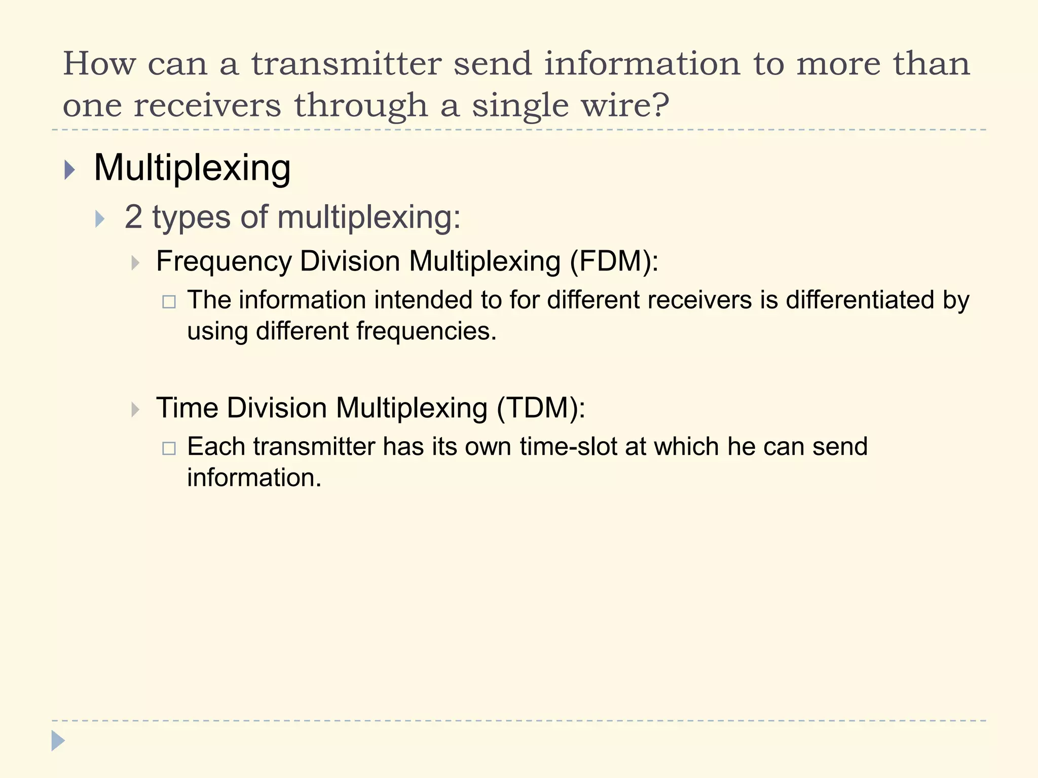
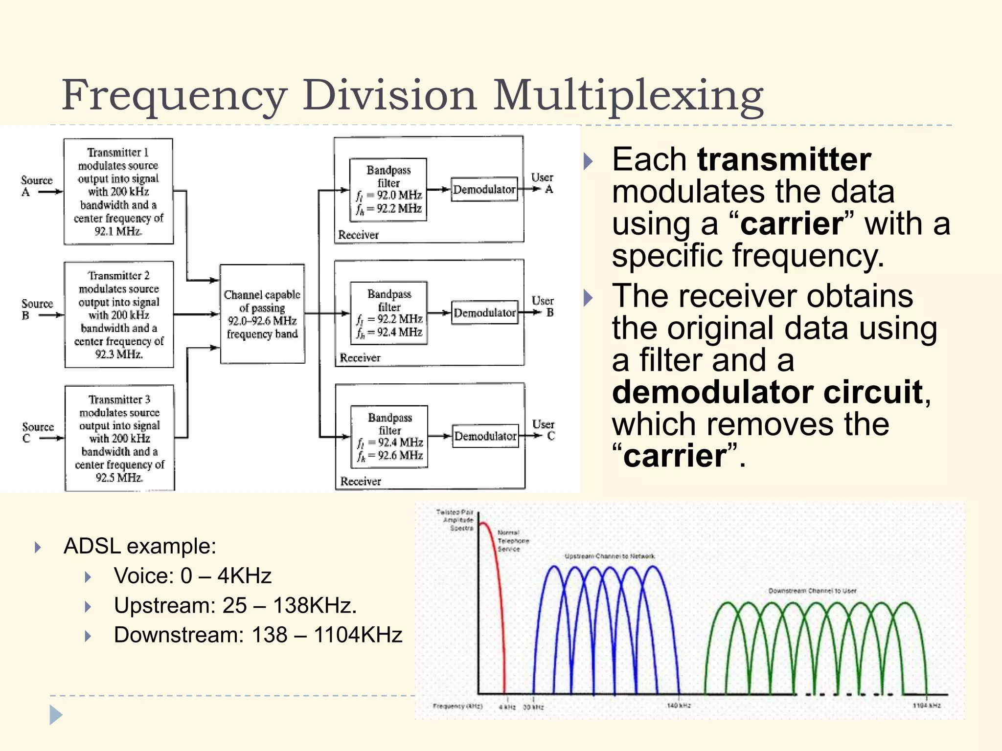
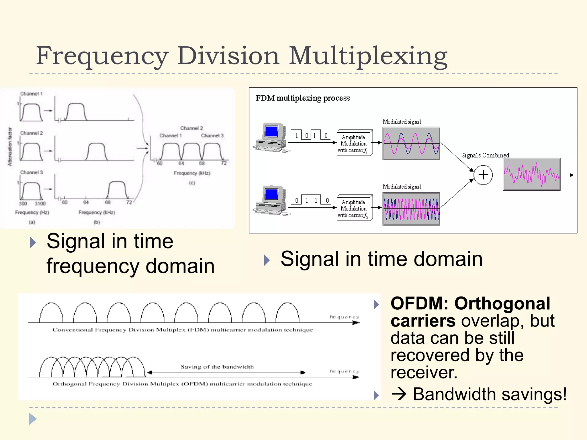
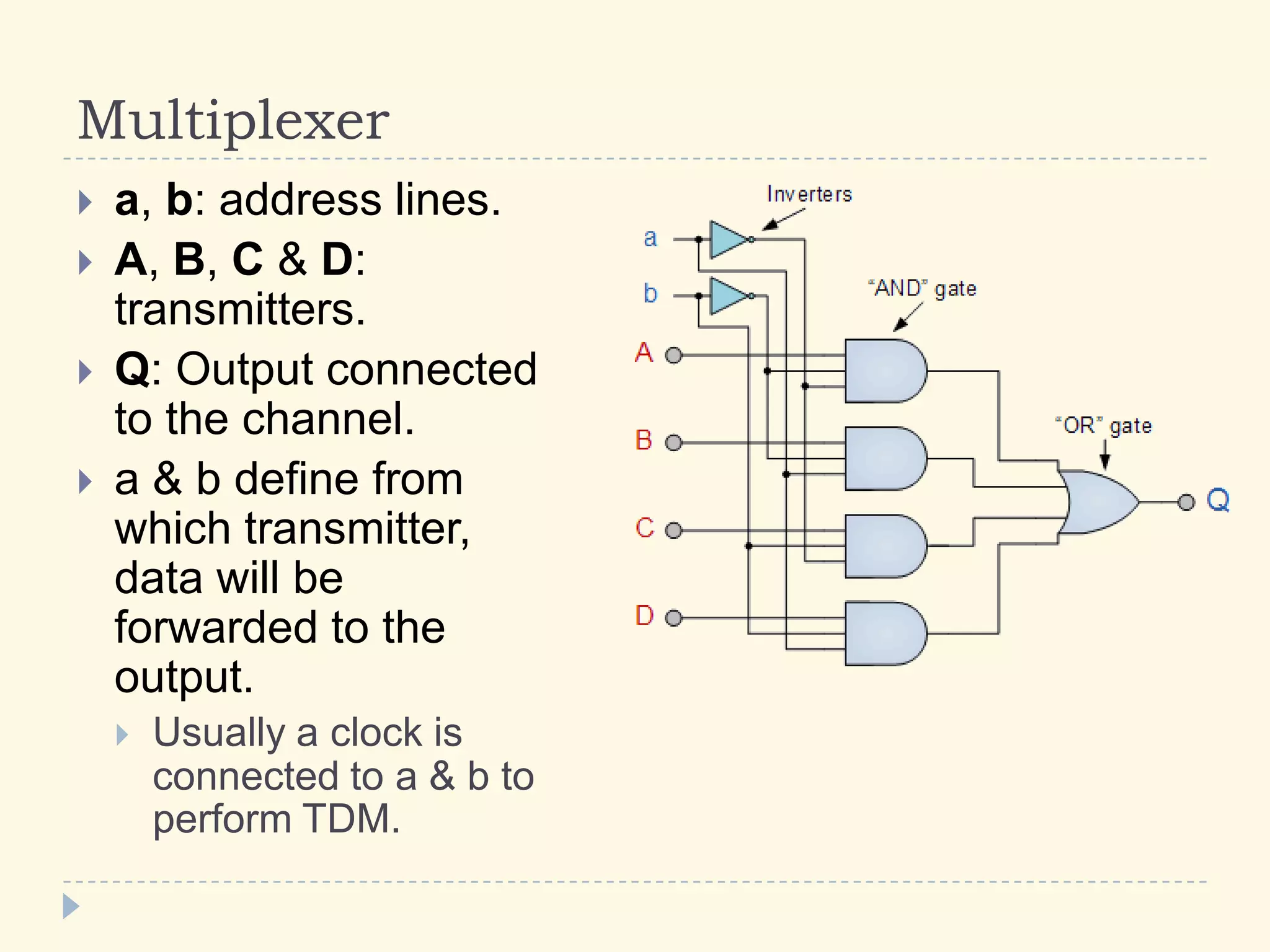
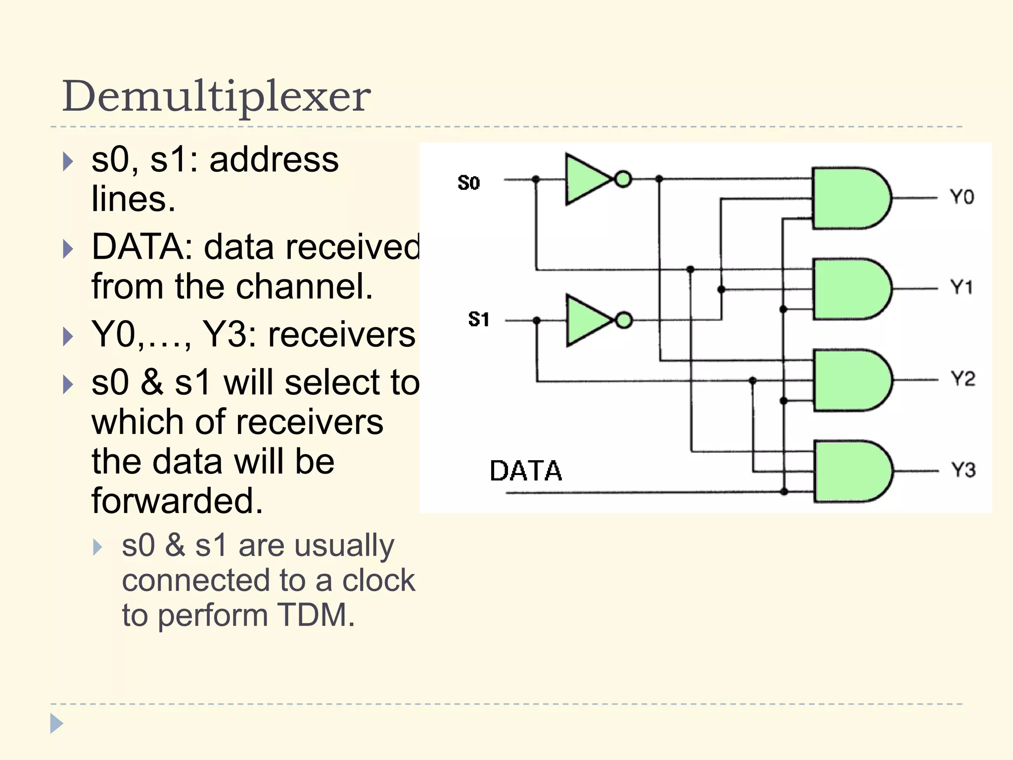
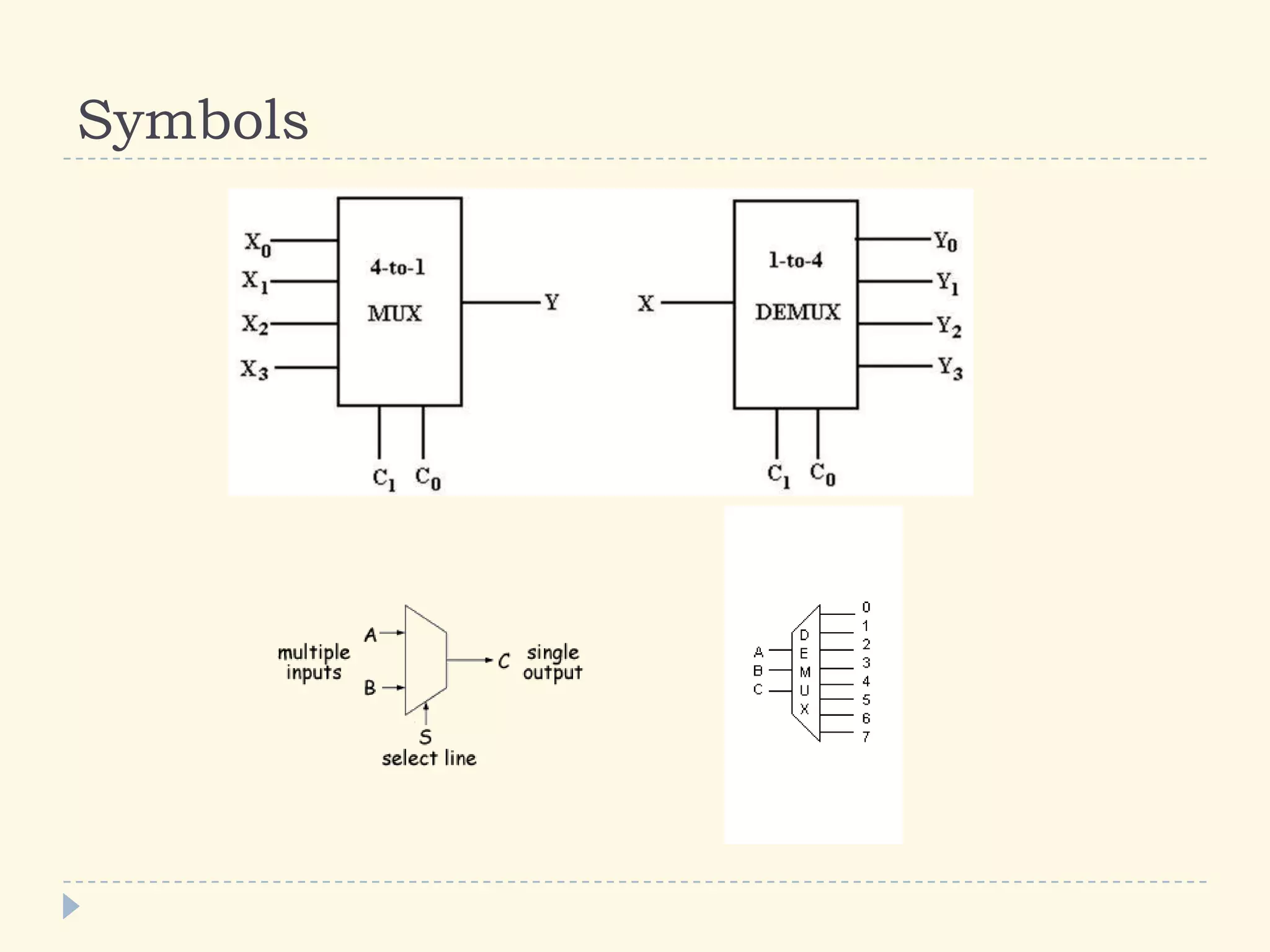
Module 5: Digital Techniques and
Electronic Instrument Systems
5.9 Multiplexing
Multiplexing
 Simplex bus:
 Data flow always
in one way.
 Half duplex bus:
 Send and receive
but not in the
same.
 Full duplex bus:
 Send and receive
simultaneously.
How can a transmitter send information to more than
one receivers through a single wire?
 Multiplexing
 2 types of multiplexing:
 Frequency Division Multiplexing (FDM):
 The information intended to for different receivers is differentiated by
using different frequencies.
 Time Division Multiplexing (TDM):
 Each transmitter has its own time-slot at which he can send
information.
Frequency Division Multiplexing
 Each transmitter
modulates the data
using a “carrier” with a
specific frequency.
 The receiver obtains
the original data using
a filter and a
demodulator circuit,
which removes the
“carrier”.
 ADSL example:
 Voice: 0 – 4KHz
 Upstream: 25 – 138KHz.
 Downstream: 138 – 1104KHz
Frequency Division Multiplexing
 Signal in time domain
 Signal in time
frequency domain
 OFDM: Orthogonal
carriers overlap, but
data can be still
recovered by the
receiver.
  Bandwidth savings!
Time Division Multiplexing
 Each receiver has a
specific timeslot.
 Multiplexer receives
one bit form each
transmitter in order,
combines them to a
TDM frame and
sends them to the
channel.
 Demultiplexer
receives the TDM
frame and gives
each bit the
appropriate receiver
in order.
Multiplexer
 a, b: address lines.
 A, B, C & D:
transmitters.
 Q: Output connected
to the channel.
 a & b define from
which transmitter,
data will be
forwarded to the
output.
 Usually a clock is
connected to a & b to
perform TDM.
Demultiplexer
 s0, s1: address
lines.
 DATA: data received
from the channel.
 Y0,…, Y3: receivers.
 s0 & s1 will select to
which of receivers
the data will be
forwarded.
 s0 & s1 are usually
connected to a clock
to perform TDM.
Symbols

5.9 Multiplexing

  • 1.
    Module 5: DigitalTechniques and Electronic Instrument Systems 5.9 Multiplexing
  • 2.
    Multiplexing  Simplex bus: Data flow always in one way.  Half duplex bus:  Send and receive but not in the same.  Full duplex bus:  Send and receive simultaneously.
  • 3.
    How can atransmitter send information to more than one receivers through a single wire?  Multiplexing  2 types of multiplexing:  Frequency Division Multiplexing (FDM):  The information intended to for different receivers is differentiated by using different frequencies.  Time Division Multiplexing (TDM):  Each transmitter has its own time-slot at which he can send information.
  • 4.
    Frequency Division Multiplexing Each transmitter modulates the data using a “carrier” with a specific frequency.  The receiver obtains the original data using a filter and a demodulator circuit, which removes the “carrier”.  ADSL example:  Voice: 0 – 4KHz  Upstream: 25 – 138KHz.  Downstream: 138 – 1104KHz
  • 5.
    Frequency Division Multiplexing Signal in time domain  Signal in time frequency domain  OFDM: Orthogonal carriers overlap, but data can be still recovered by the receiver.   Bandwidth savings!
  • 6.
    Time Division Multiplexing Each receiver has a specific timeslot.  Multiplexer receives one bit form each transmitter in order, combines them to a TDM frame and sends them to the channel.  Demultiplexer receives the TDM frame and gives each bit the appropriate receiver in order.
  • 7.
    Multiplexer  a, b:address lines.  A, B, C & D: transmitters.  Q: Output connected to the channel.  a & b define from which transmitter, data will be forwarded to the output.  Usually a clock is connected to a & b to perform TDM.
  • 8.
    Demultiplexer  s0, s1:address lines.  DATA: data received from the channel.  Y0,…, Y3: receivers.  s0 & s1 will select to which of receivers the data will be forwarded.  s0 & s1 are usually connected to a clock to perform TDM.
  • 9.