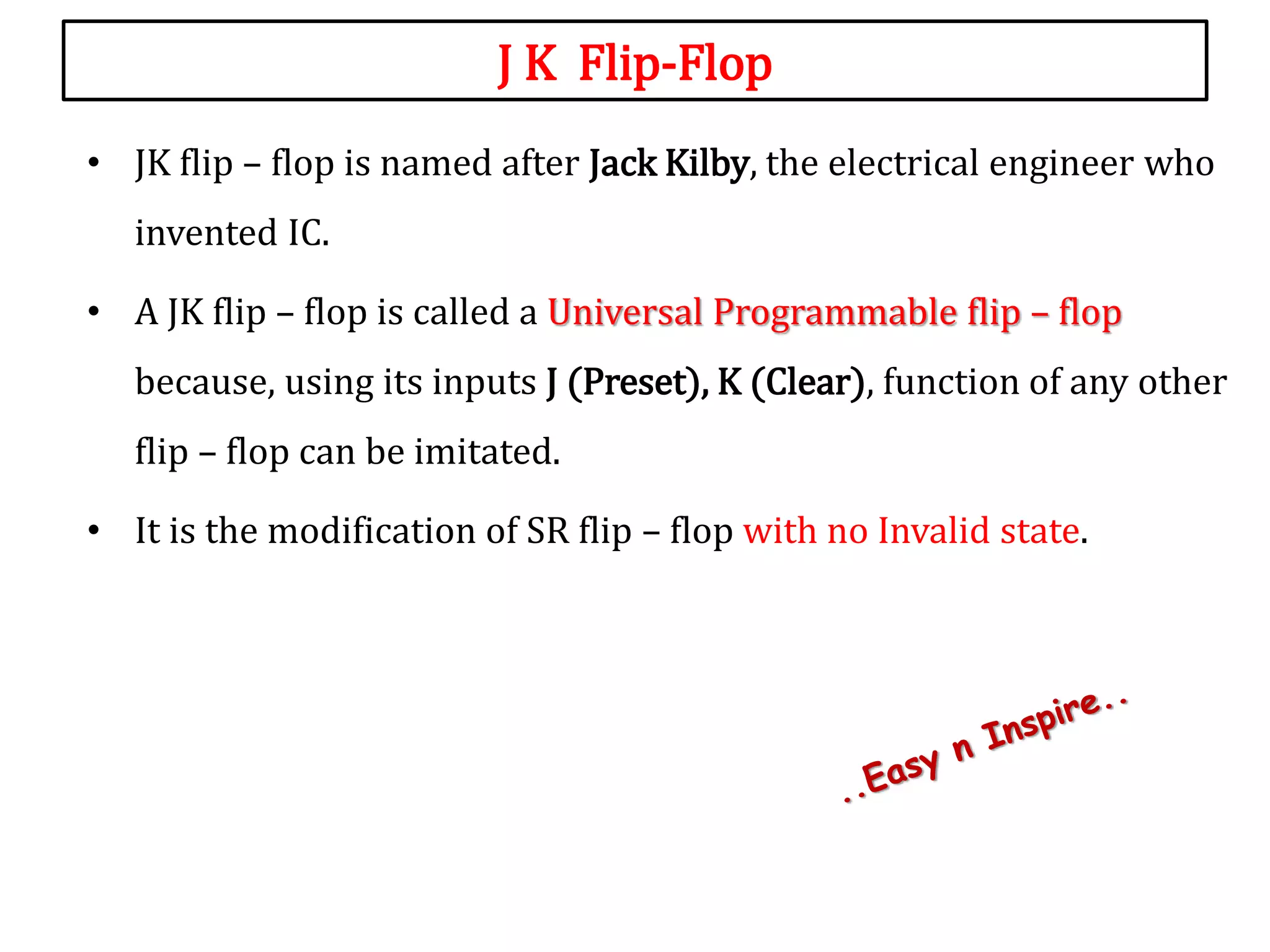
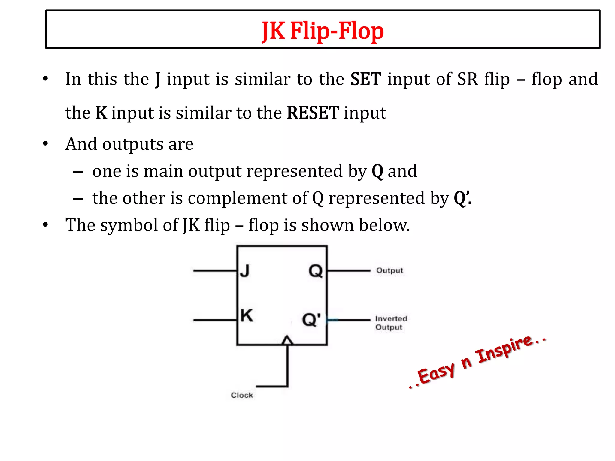
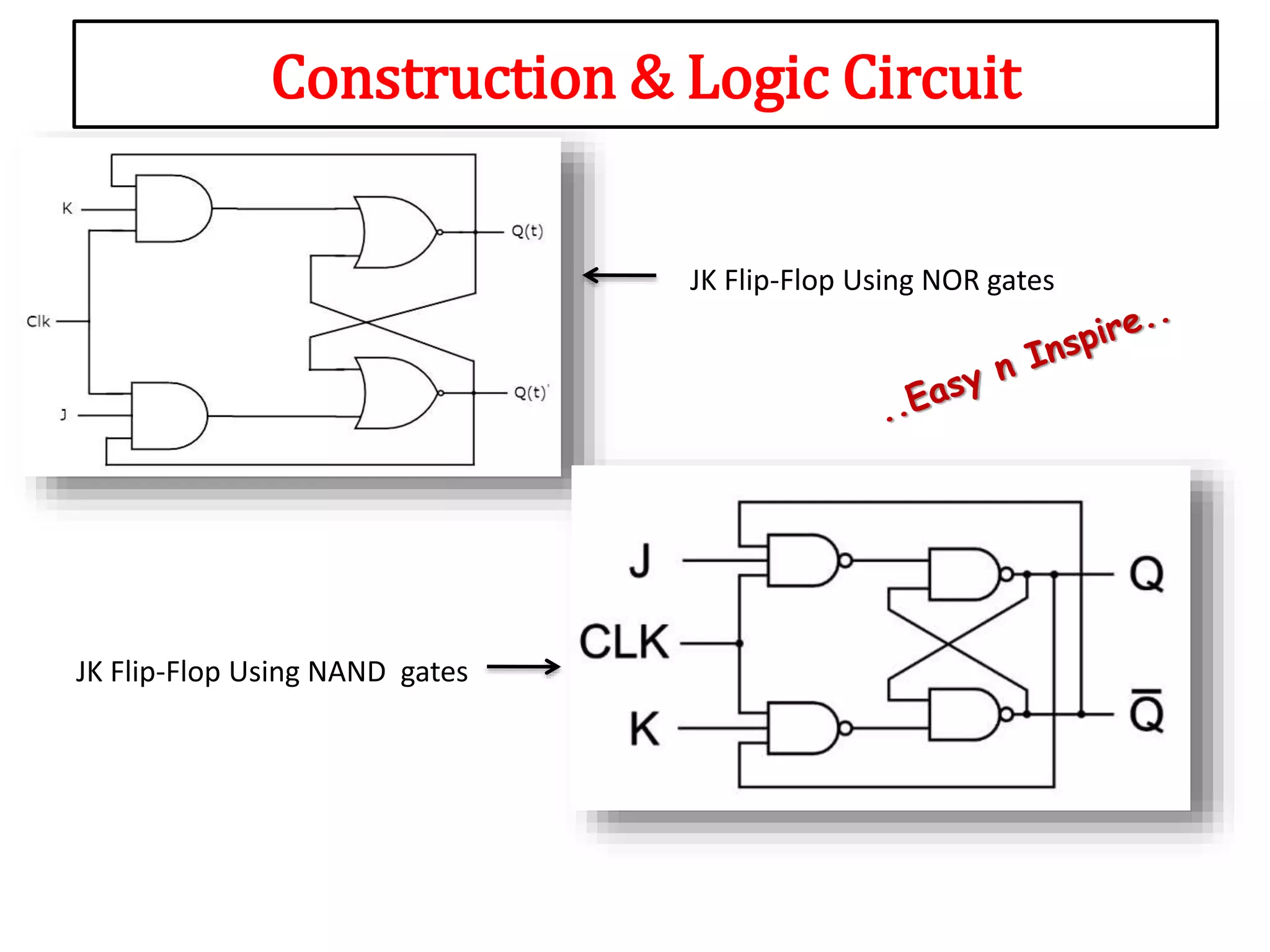
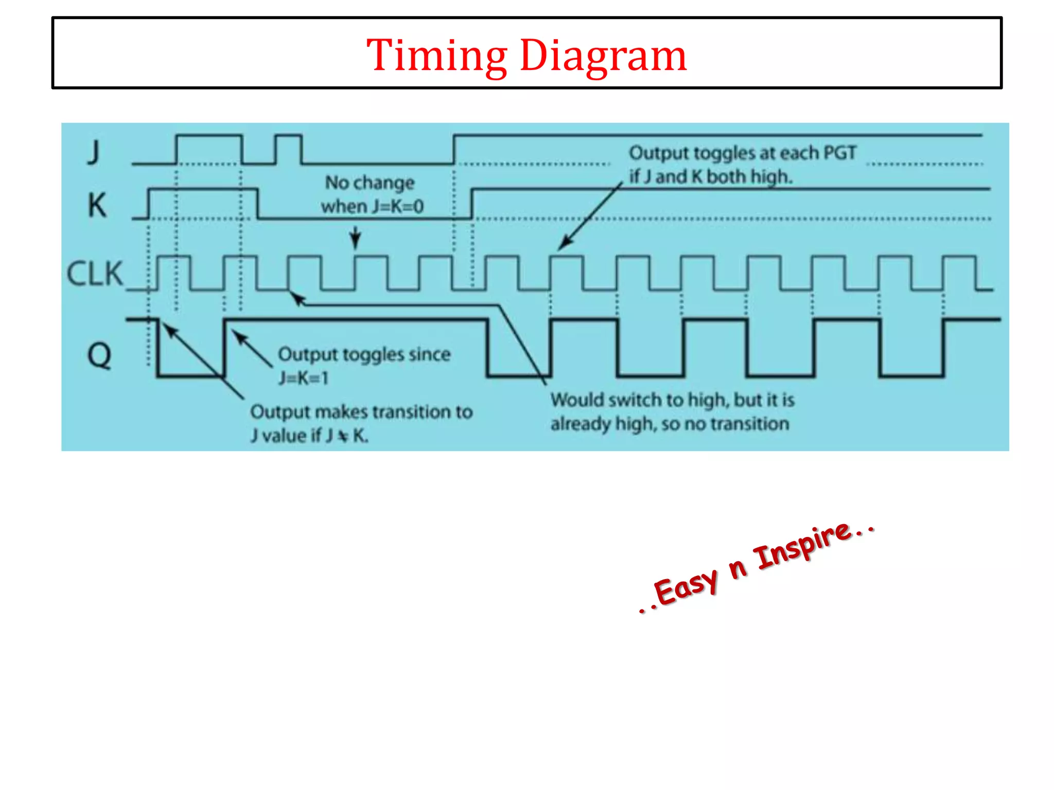
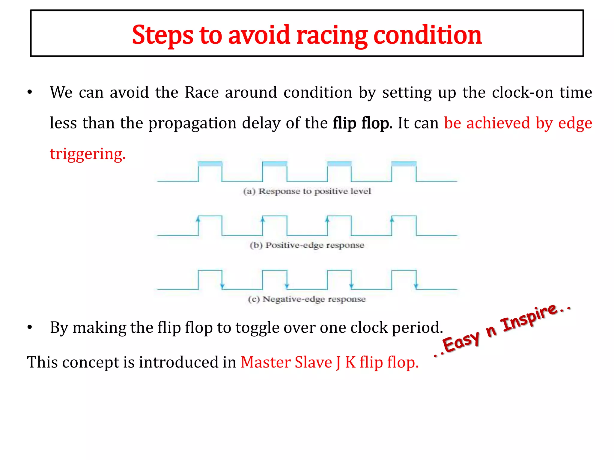
JK Flip-Flop
Today's Topic
Sequential Logic Circuits
• JK Flip-Flop
Why JK Flip-Flop
• SR
• D
J K Flip-Flop
• JK flip – flop is named after Jack Kilby, the electrical engineer who
invented IC.
• A JK flip – flop is called a Universal Programmable flip – flop
because, using its inputs J (Preset), K (Clear), function of any other
flip – flop can be imitated.
• It is the modification of SR flip – flop with no Invalid state.
JK Flip-Flop
• In this the J input is similar to the SET input of SR flip – flop and
the K input is similar to the RESET input
• And outputs are
– one is main output represented by Q and
– the other is complement of Q represented by Q’.
• The symbol of JK flip – flop is shown below.
Construction & Logic Circuit
JK Flip-Flop Using NOR gates
JK Flip-Flop Using NAND gates
NAND Truth table
1. J=0 , K=1 Q=0 Q’=1
2. J=0 , K=0 Q= 0 Q’= 1
3. J=1 , K=0 Q= 1 Q’= 0
4. J=0 , K=0 Q= 1 Q’= 0
5. J=1 , K=1 Q= T Q’= T
A B Y
0 0 1
0 1 1
1 0 1
1 1 0
Clk J K Q Q’ State
↑ » 1 0 0 Q Q’ NC
↑ » 1 0 1 0 1 RESET
↑ » 1 1 0 1 0 SET
↑ » 1 1 1 T T Toggle
» 0 X X - - -
JK Flip-Flop Truth Table
Clk J K Q(t) Q(t+1) State
↑ » 1 0 0 0 0
Memory / No change state
↑ » 1 0 0 1 1
↑ » 1 0 1 0 0
RESET
↑ » 1 0 1 1 0
↑ » 1 1 0 0 1
SET
↑ » 1 1 0 1 1
↑ » 1 1 1 0 1 0 1 0..
Toggle
↑ » 1 1 1 1 0 1 0 1..
JK Flip-Flop Characteristic Table
 Toggle means switch between two states.
 Conditions for toggle in JK- flip flop :
 Both J and K should be 1.
 Clock should be present( Here I have considered +ve clock/rising edge)
Timing Diagram
Review
• A J-K flip-flop is nothing more than an S-R flip-flop with an added layer
of feedback.
• This eliminates the invalid condition.
• When both J and K inputs are activated (J=1,K=1), and the clock input
is applied then the circuit will toggle from a set state to a reset state or
vice versa.
• The limitation of JK Latch is Race Around Condition (in JK Latch)
 Race around condition means toggling is happening at the output many
a time within a single clock period.
Steps to avoid racing condition
• We can avoid the Race around condition by setting up the clock-on time
less than the propagation delay of the flip flop. It can be achieved by edge
triggering.
• By making the flip flop to toggle over one clock period.
This concept is introduced in Master Slave J K flip flop.
In Next Class
• Master Slave JK Flip Flop
• A

JK flip flop in Digital electronics

  • 1.
  • 2.
    Today's Topic Sequential LogicCircuits • JK Flip-Flop
  • 3.
  • 4.
    J K Flip-Flop •JK flip – flop is named after Jack Kilby, the electrical engineer who invented IC. • A JK flip – flop is called a Universal Programmable flip – flop because, using its inputs J (Preset), K (Clear), function of any other flip – flop can be imitated. • It is the modification of SR flip – flop with no Invalid state.
  • 5.
    JK Flip-Flop • Inthis the J input is similar to the SET input of SR flip – flop and the K input is similar to the RESET input • And outputs are – one is main output represented by Q and – the other is complement of Q represented by Q’. • The symbol of JK flip – flop is shown below.
  • 6.
    Construction & LogicCircuit JK Flip-Flop Using NOR gates JK Flip-Flop Using NAND gates
  • 7.
    NAND Truth table 1.J=0 , K=1 Q=0 Q’=1 2. J=0 , K=0 Q= 0 Q’= 1 3. J=1 , K=0 Q= 1 Q’= 0 4. J=0 , K=0 Q= 1 Q’= 0 5. J=1 , K=1 Q= T Q’= T A B Y 0 0 1 0 1 1 1 0 1 1 1 0
  • 8.
    Clk J KQ Q’ State ↑ » 1 0 0 Q Q’ NC ↑ » 1 0 1 0 1 RESET ↑ » 1 1 0 1 0 SET ↑ » 1 1 1 T T Toggle » 0 X X - - - JK Flip-Flop Truth Table
  • 9.
    Clk J KQ(t) Q(t+1) State ↑ » 1 0 0 0 0 Memory / No change state ↑ » 1 0 0 1 1 ↑ » 1 0 1 0 0 RESET ↑ » 1 0 1 1 0 ↑ » 1 1 0 0 1 SET ↑ » 1 1 0 1 1 ↑ » 1 1 1 0 1 0 1 0.. Toggle ↑ » 1 1 1 1 0 1 0 1.. JK Flip-Flop Characteristic Table  Toggle means switch between two states.  Conditions for toggle in JK- flip flop :  Both J and K should be 1.  Clock should be present( Here I have considered +ve clock/rising edge)
  • 10.
  • 11.
    Review • A J-Kflip-flop is nothing more than an S-R flip-flop with an added layer of feedback. • This eliminates the invalid condition. • When both J and K inputs are activated (J=1,K=1), and the clock input is applied then the circuit will toggle from a set state to a reset state or vice versa. • The limitation of JK Latch is Race Around Condition (in JK Latch)  Race around condition means toggling is happening at the output many a time within a single clock period.
  • 12.
    Steps to avoidracing condition • We can avoid the Race around condition by setting up the clock-on time less than the propagation delay of the flip flop. It can be achieved by edge triggering. • By making the flip flop to toggle over one clock period. This concept is introduced in Master Slave J K flip flop.
  • 13.
    In Next Class •Master Slave JK Flip Flop
  • 14.