Downloaded 125 times

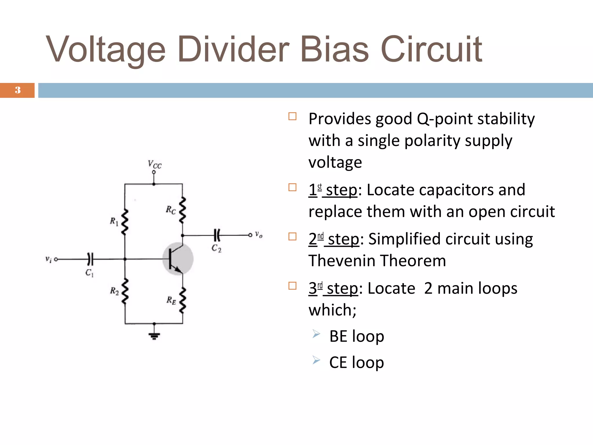


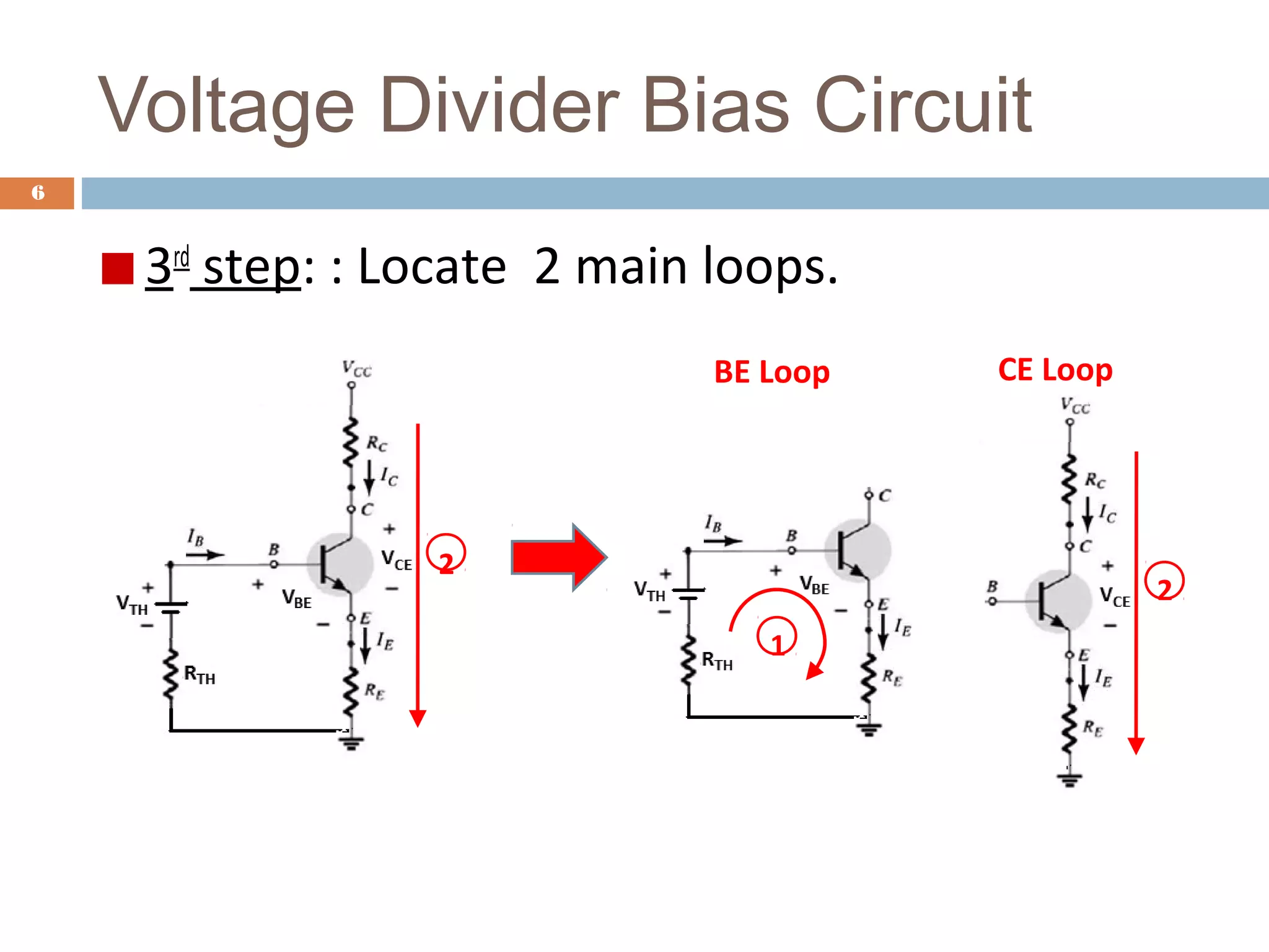


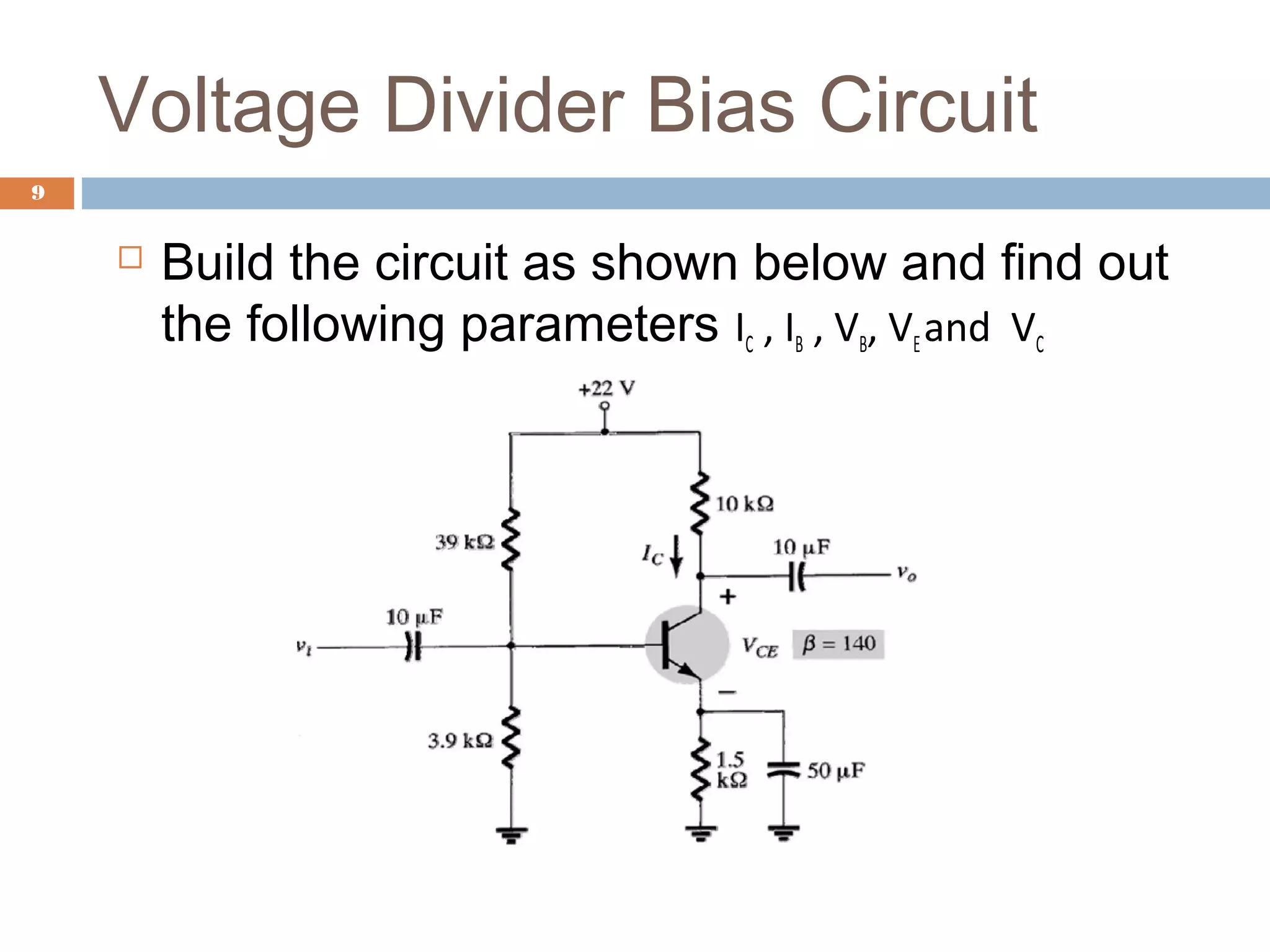


This document discusses voltage divider biasing of BJT transistors. It explains the steps to analyze a voltage divider bias circuit: 1) replace capacitors with open circuits, 2) simplify the circuit using Thevenin's theorem, and 3) identify the base-emitter and collector-emitter loops. Equations for the bias point currents and voltages are derived from loop analyses. A simulation circuit is provided to experimentally determine the bias point parameters. The full experiment can be accessed online for hands-on practice of voltage divider bias analysis.