Downloaded 99 times


![77
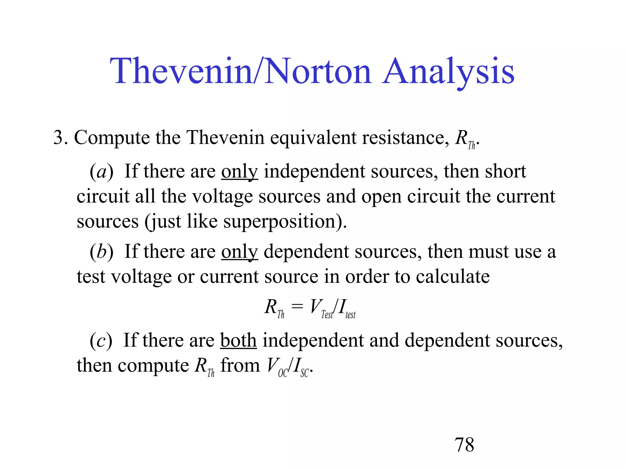
Thevenin/Norton Analysis
1. Pick a good breaking point in the circuit (cannot split a
dependent source and its control variable).
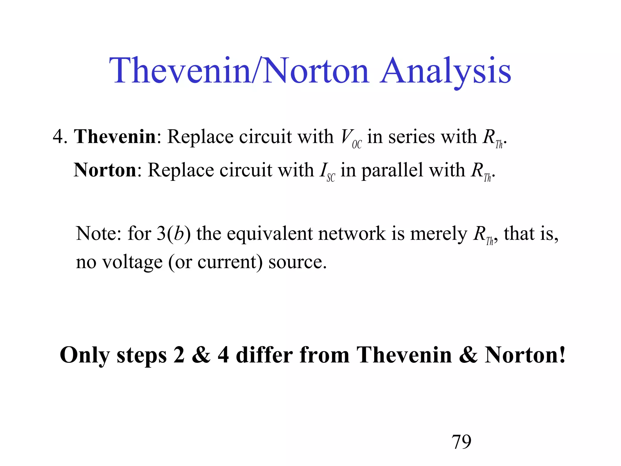
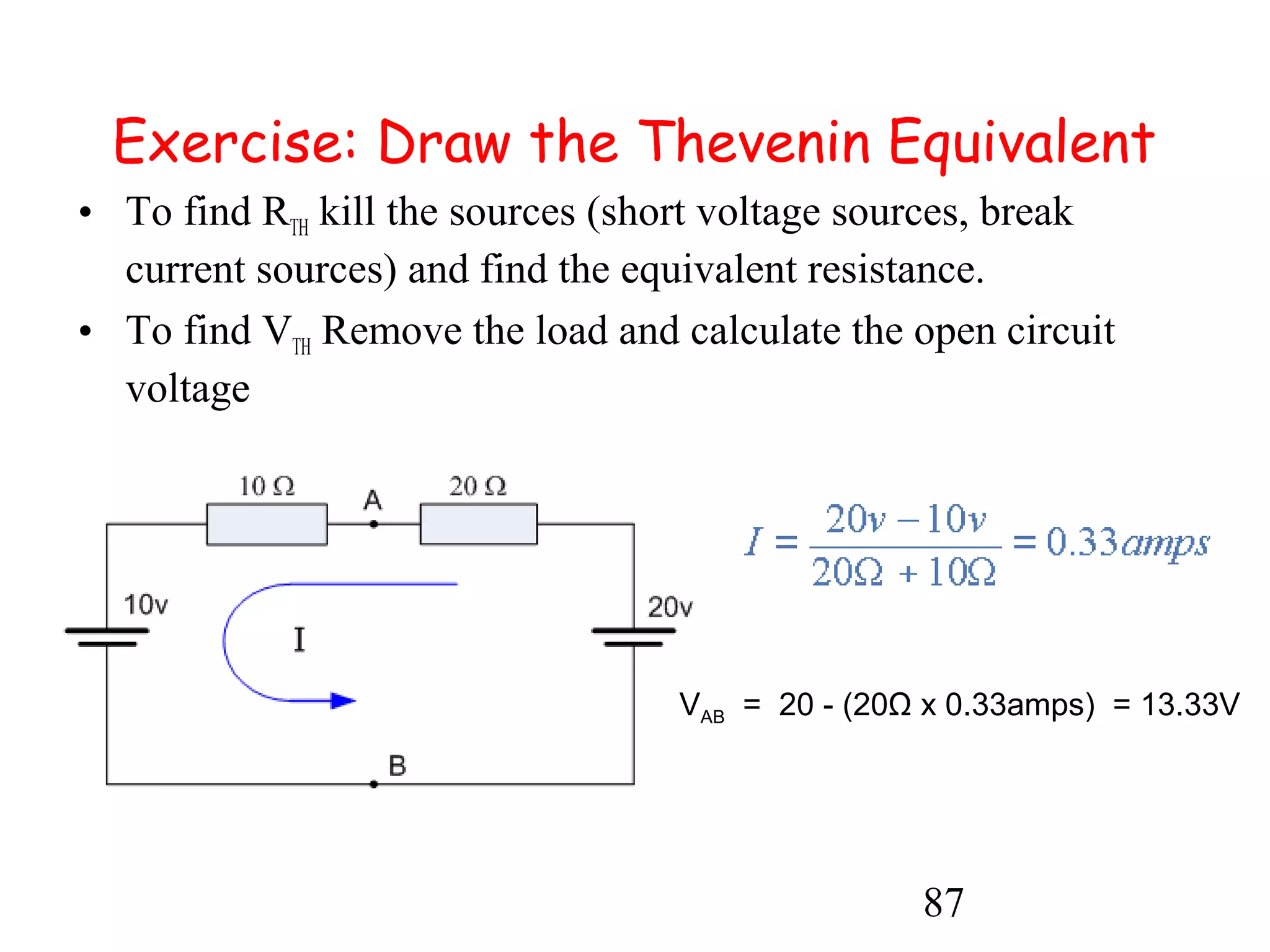
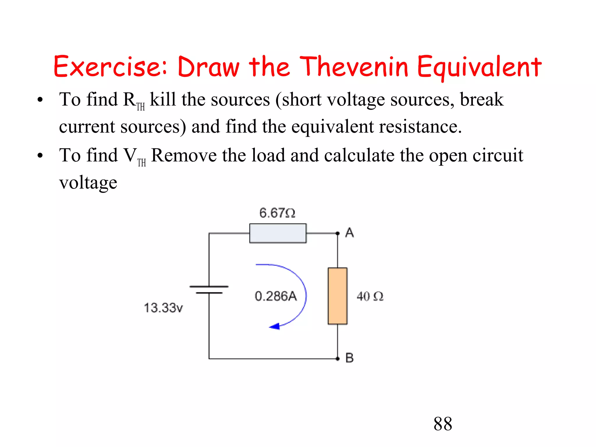
2. Thevenin: Compute the open circuit voltage, VOC.
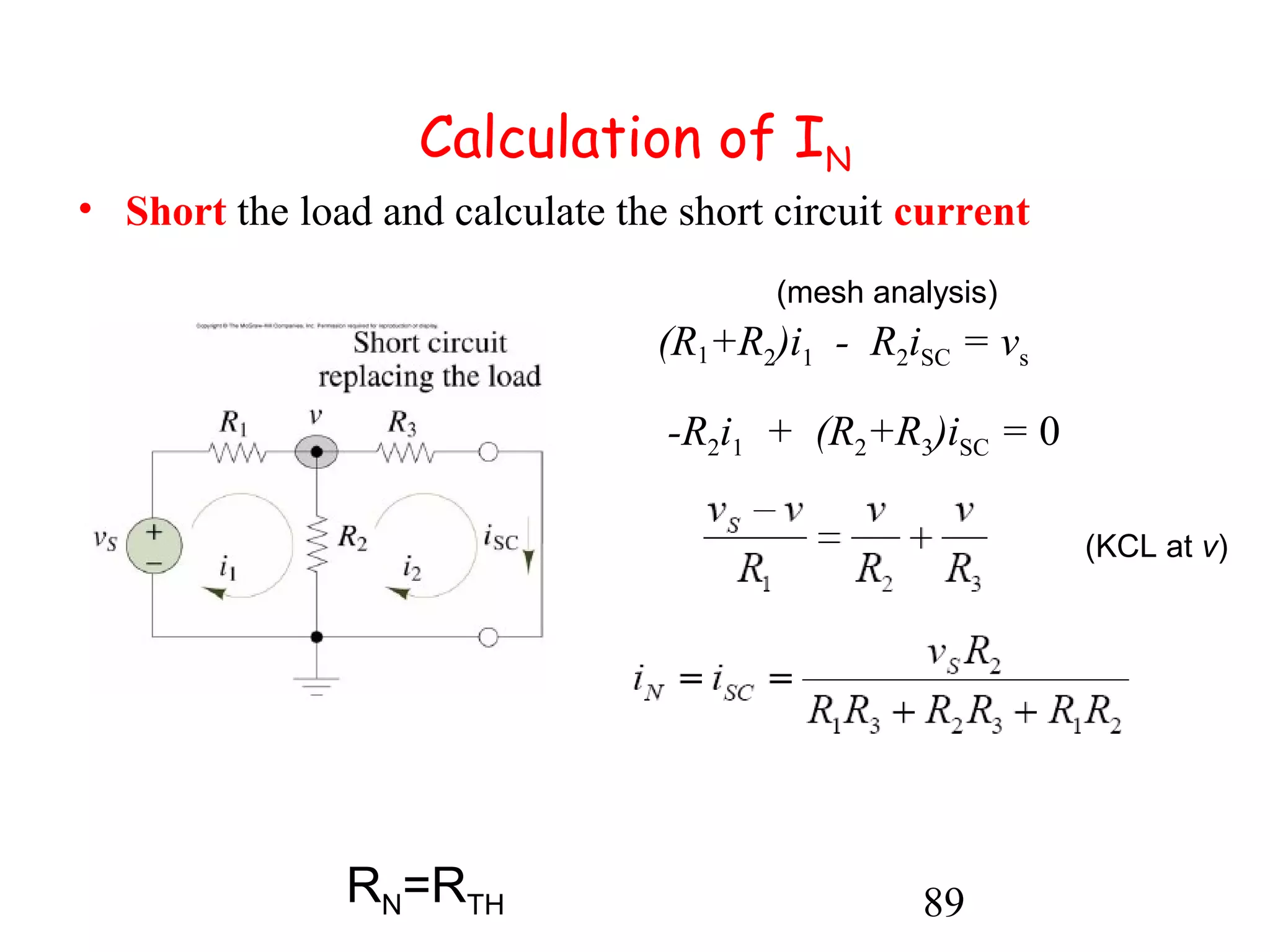
Norton: Compute the short circuit current, ISC.
For case 3(b) both VOC=0 and ISC=0 [so skip step 2]](https://image.slidesharecdn.com/topic1bbasicconceptsandtheorem-140828062543-phpapp01/75/Topic-1-b_basic_concepts_and_theorem-77-2048.jpg)

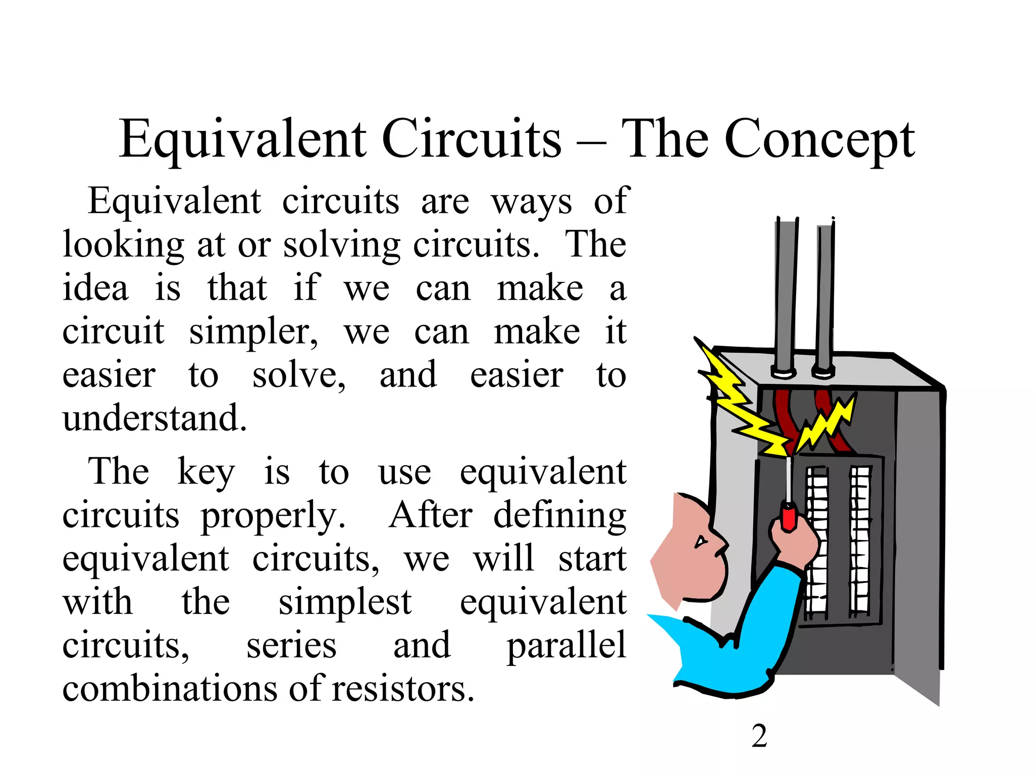
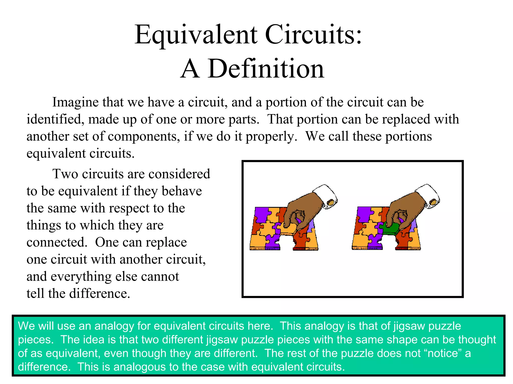
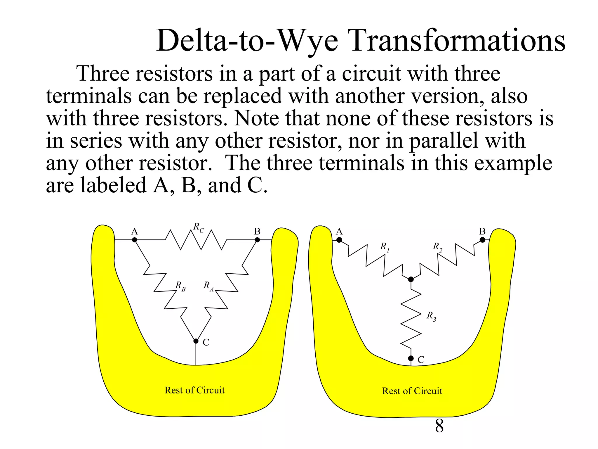
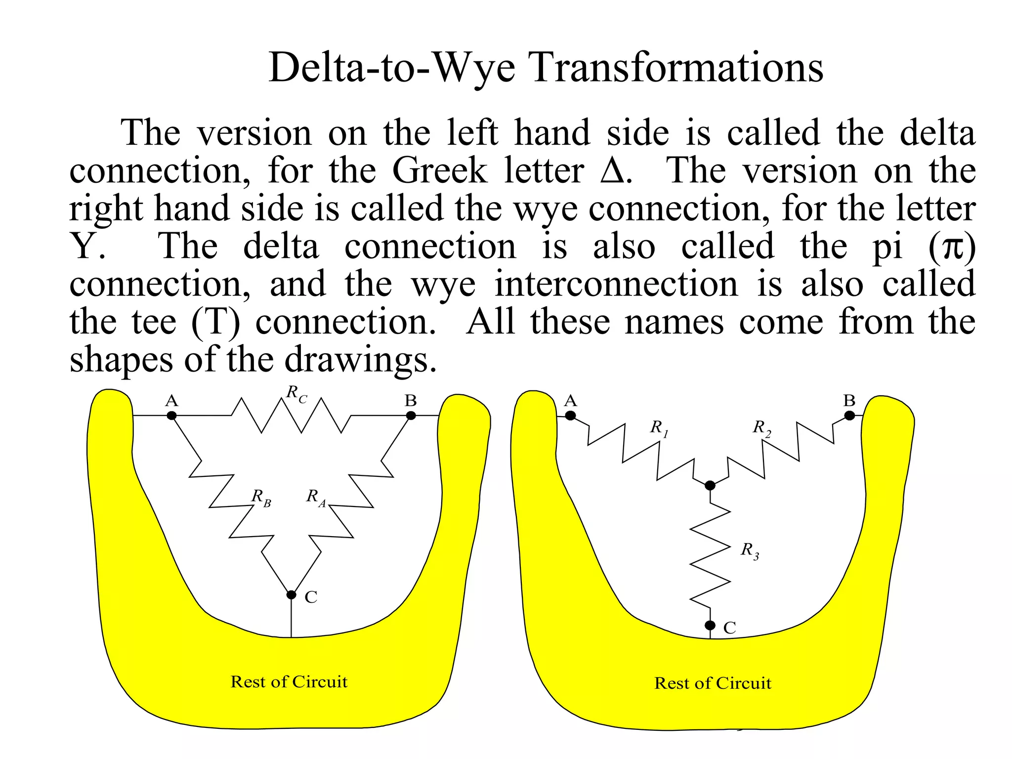
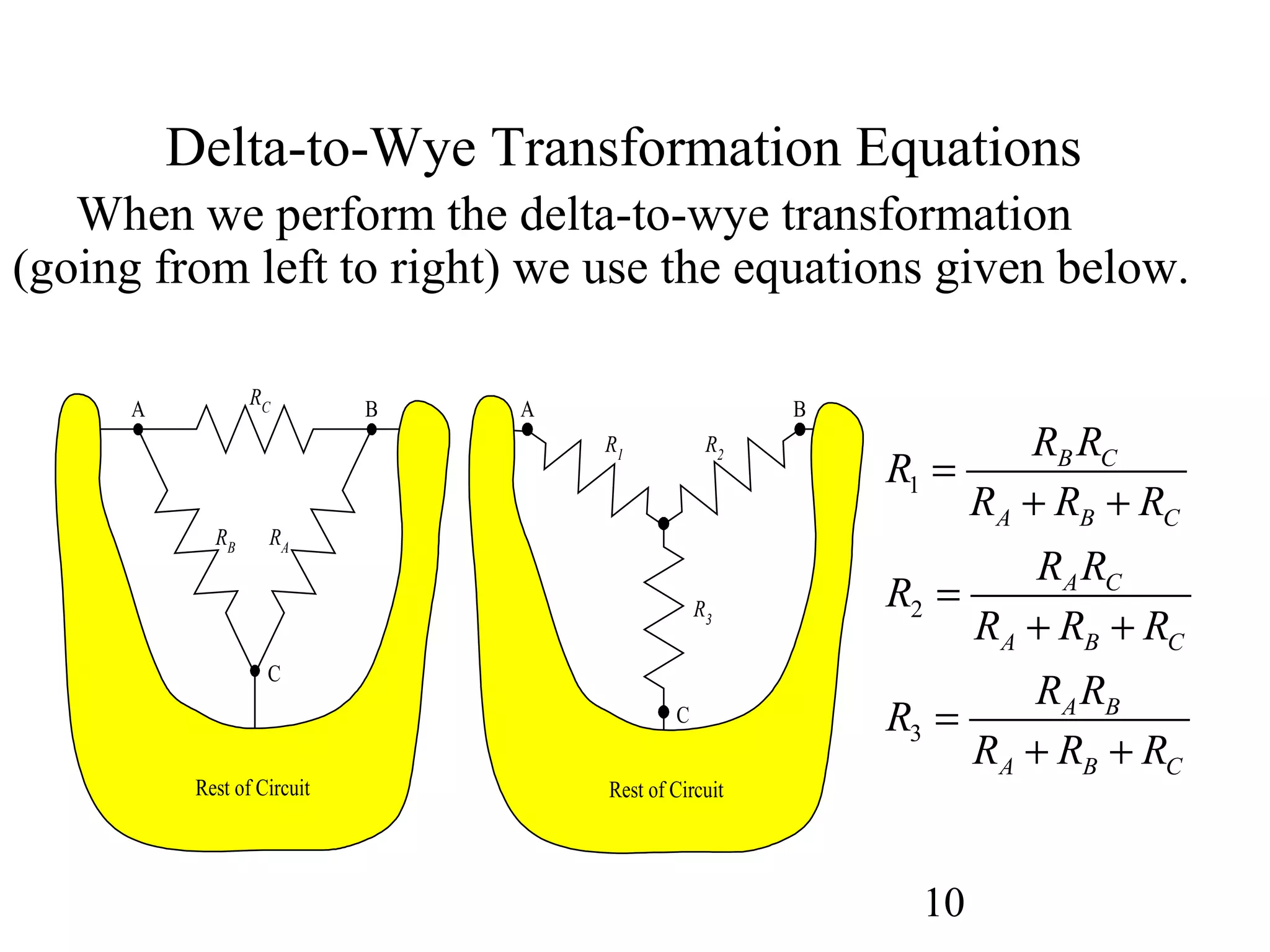
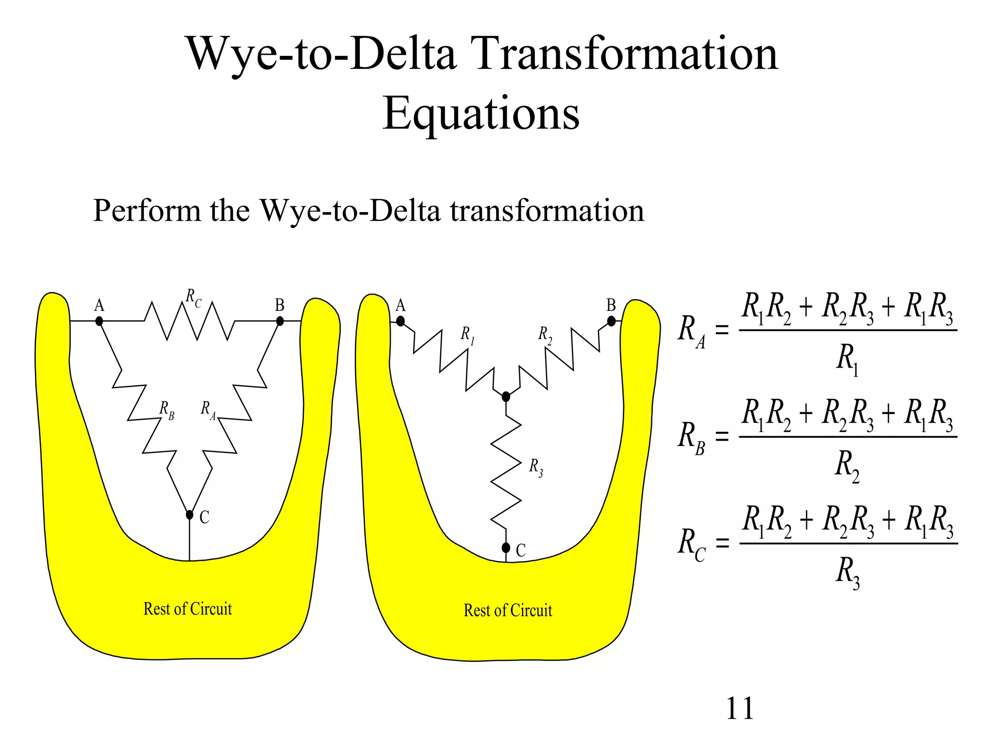
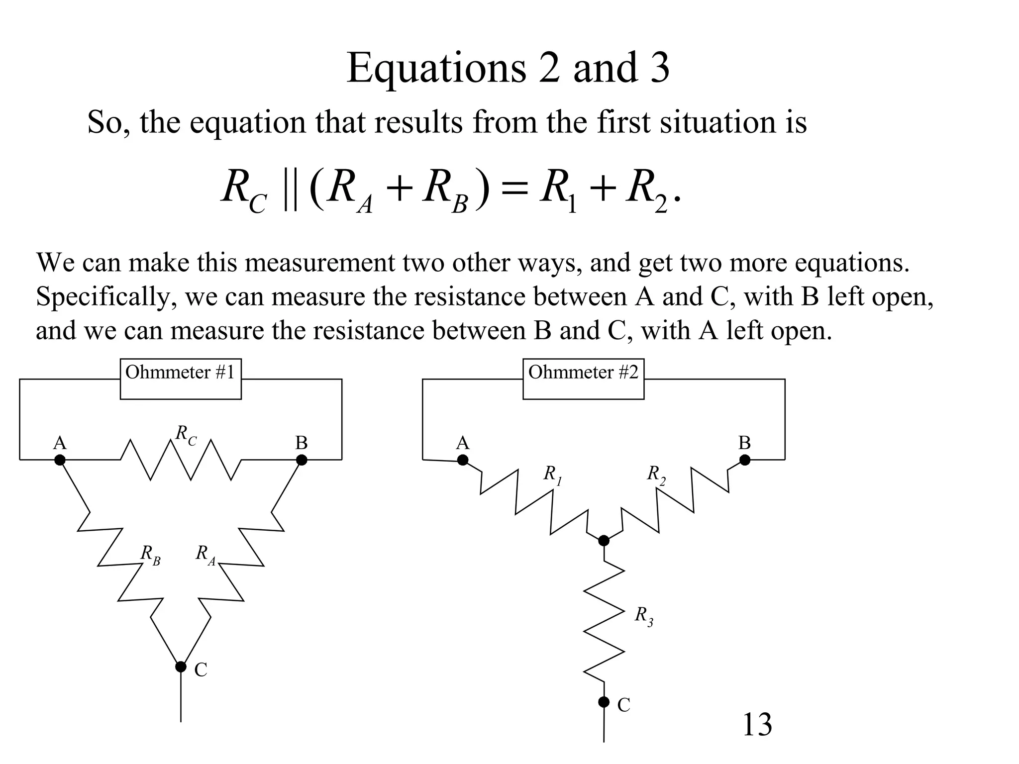
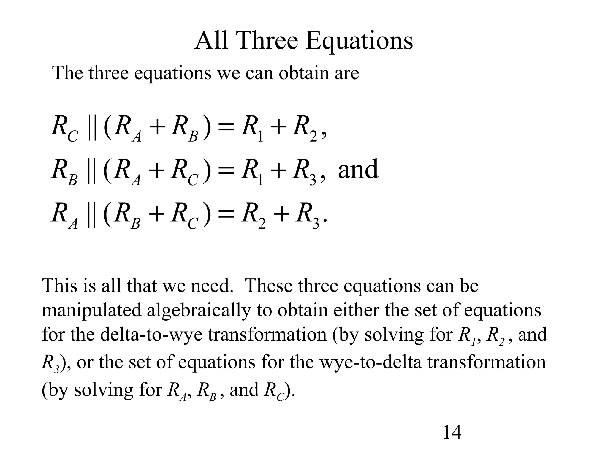
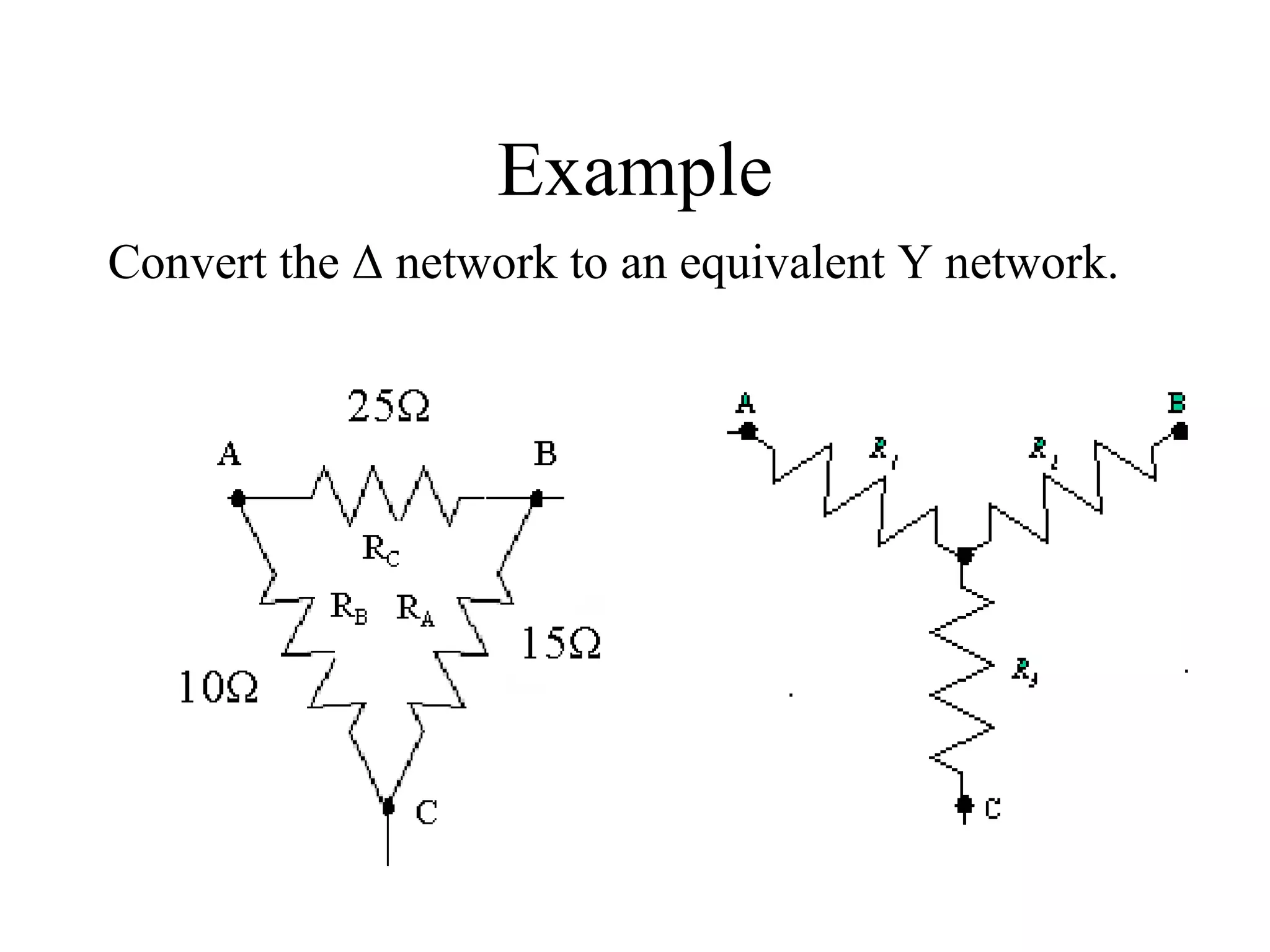
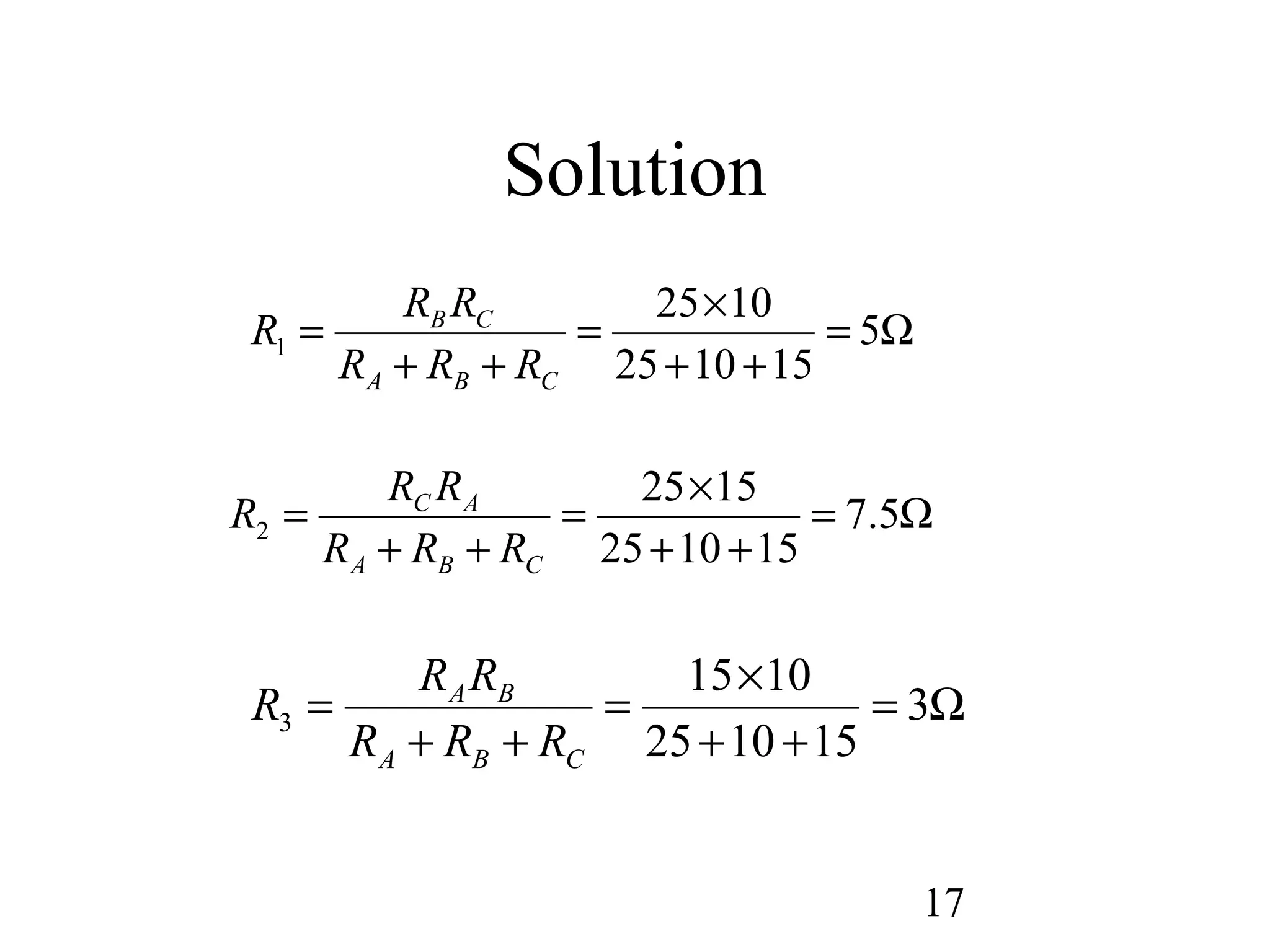
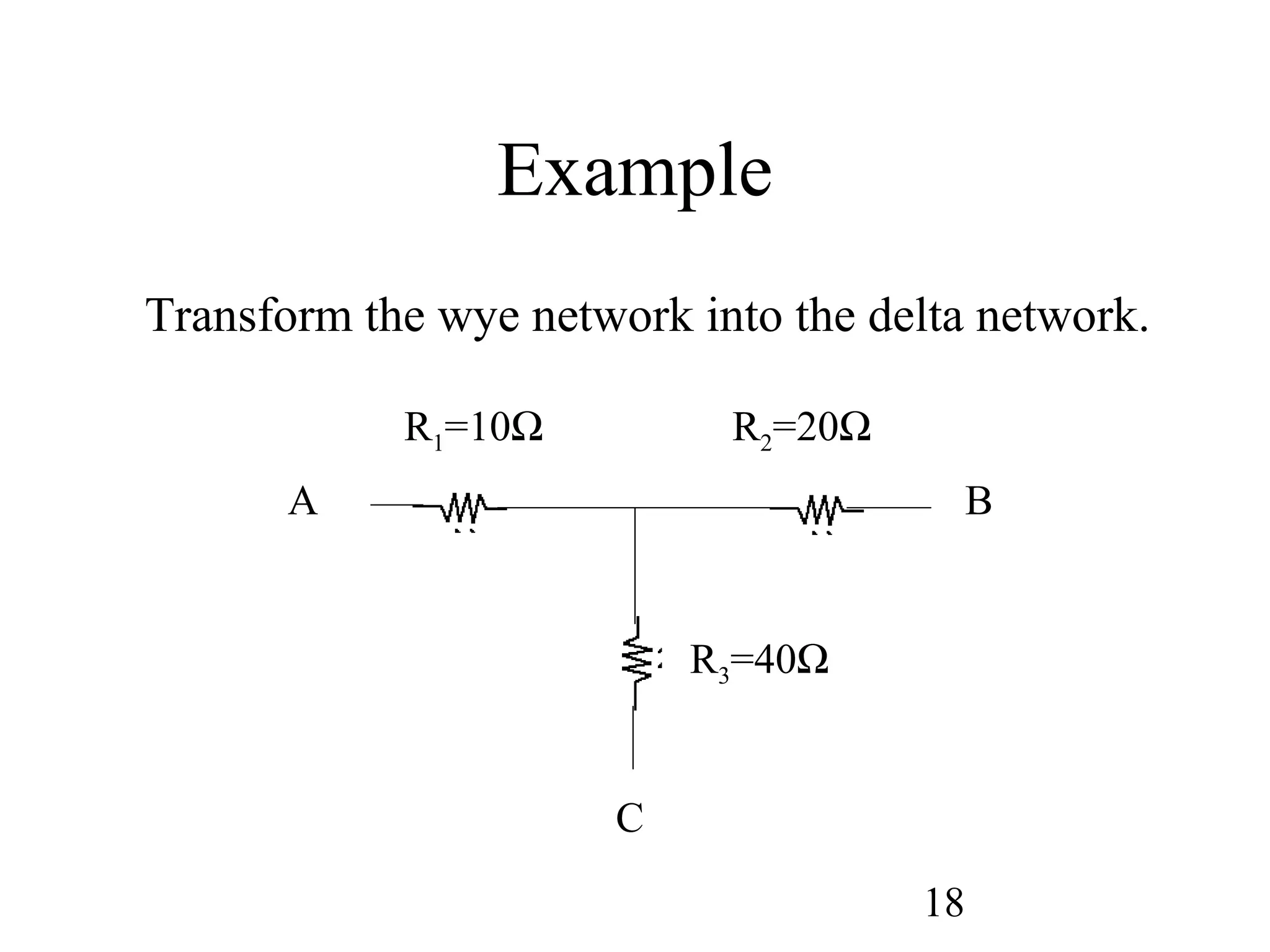
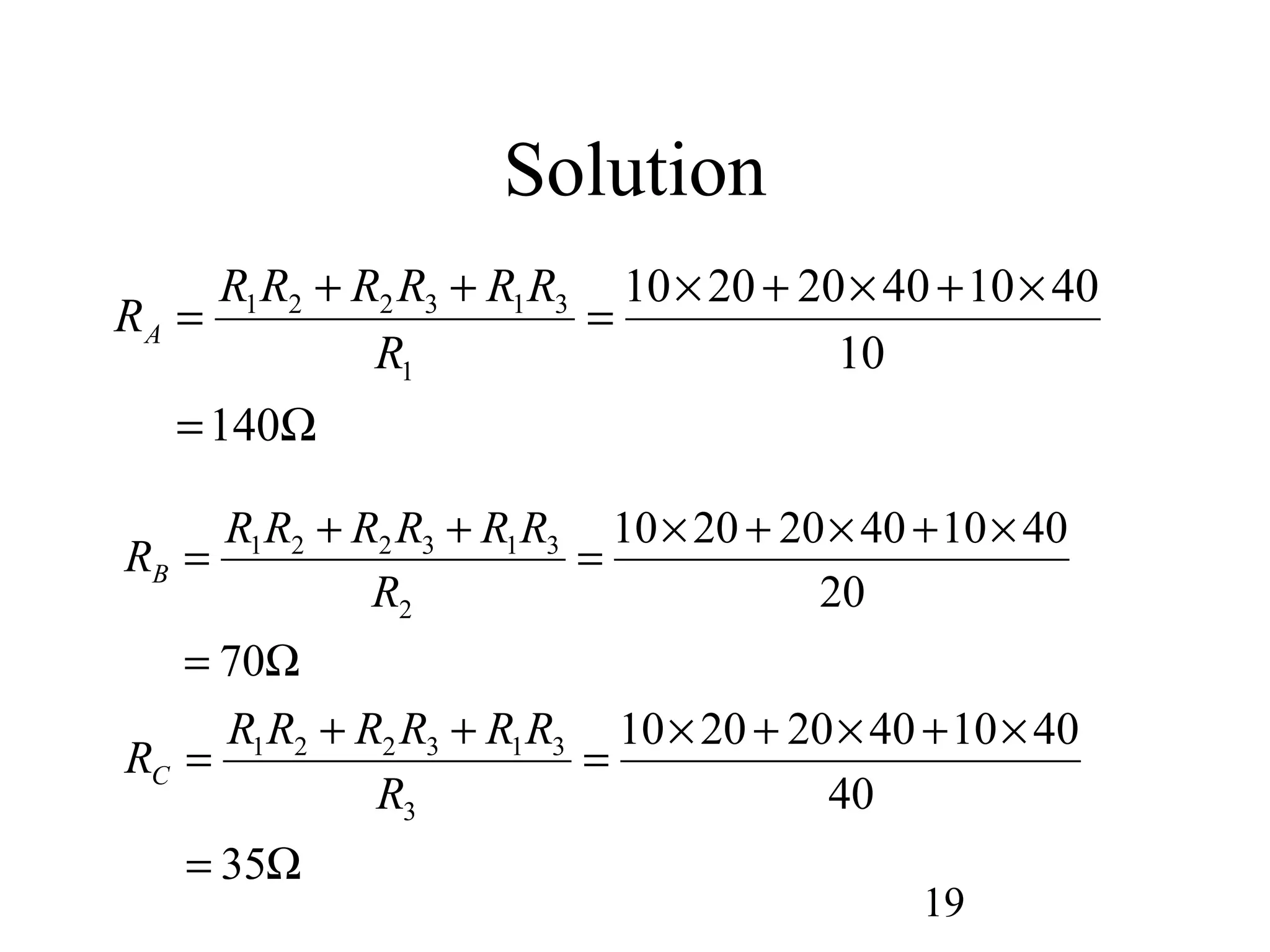
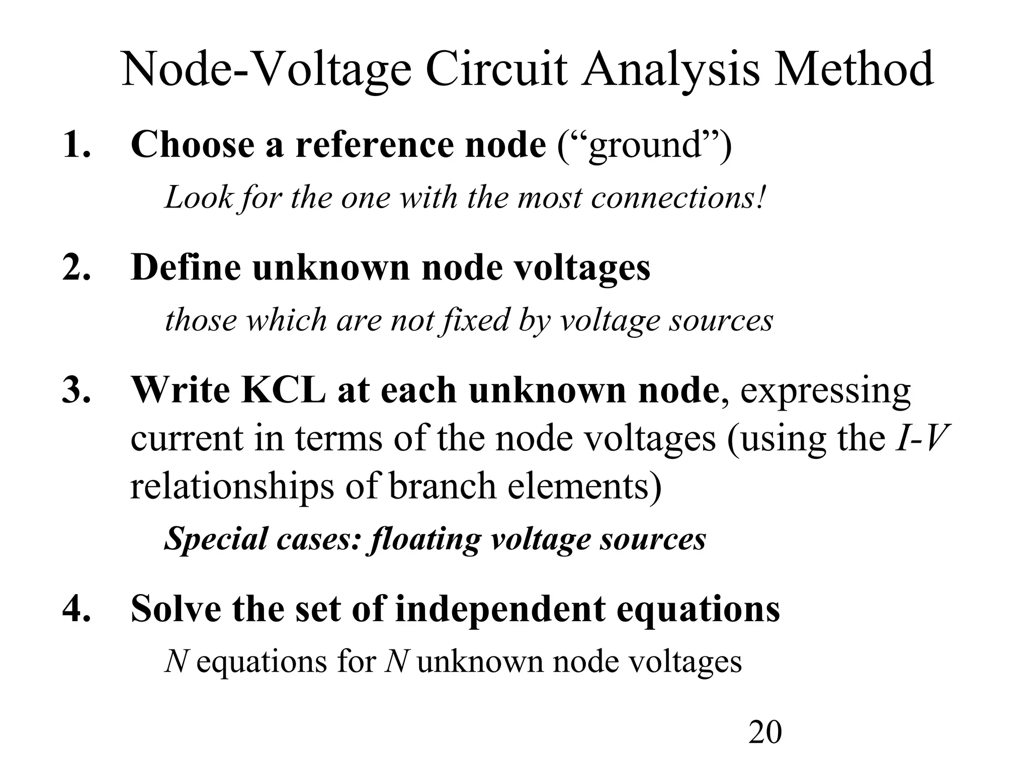
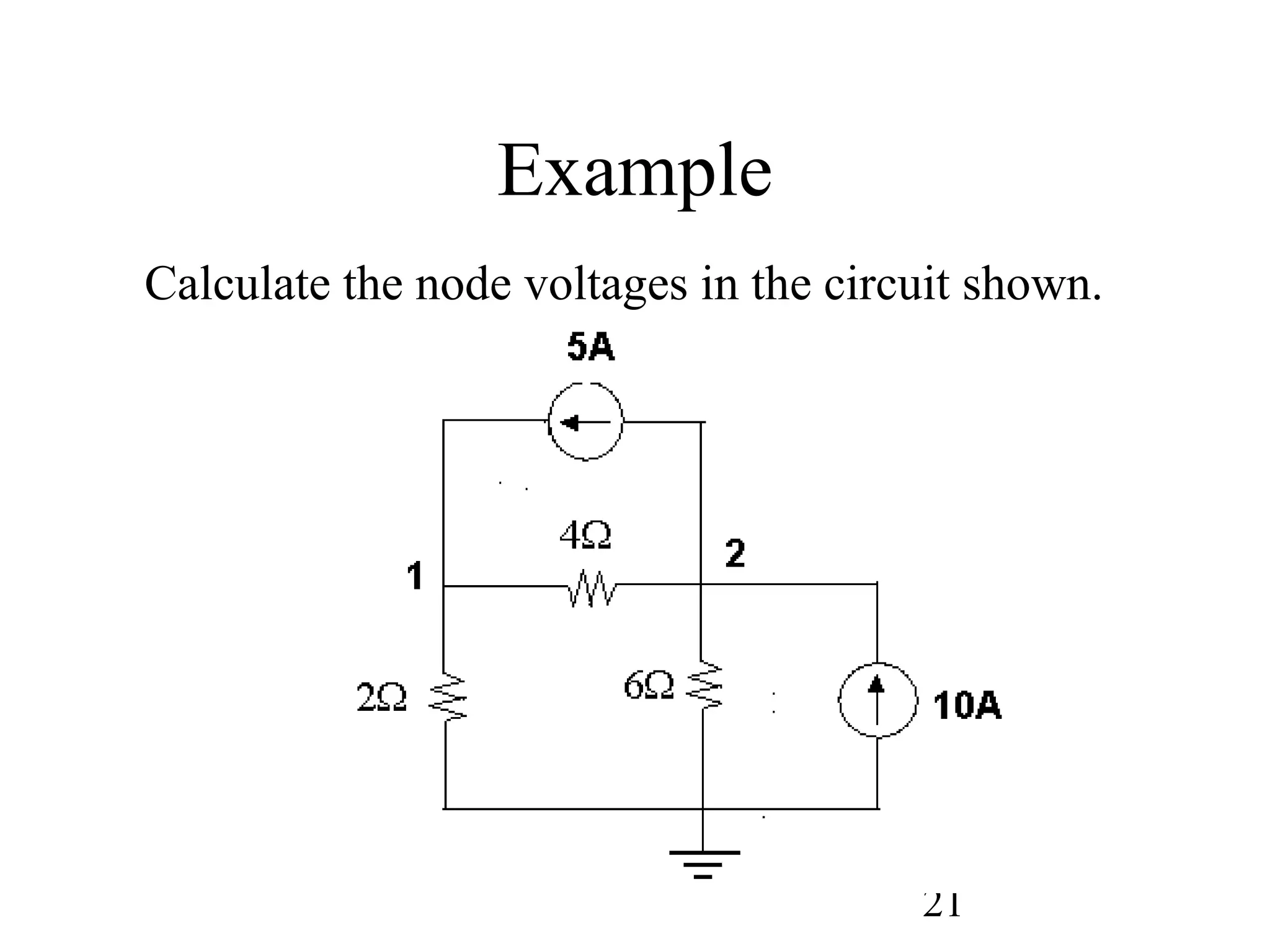
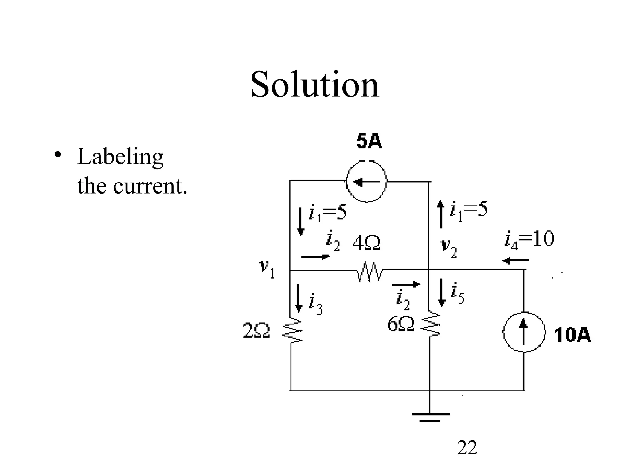
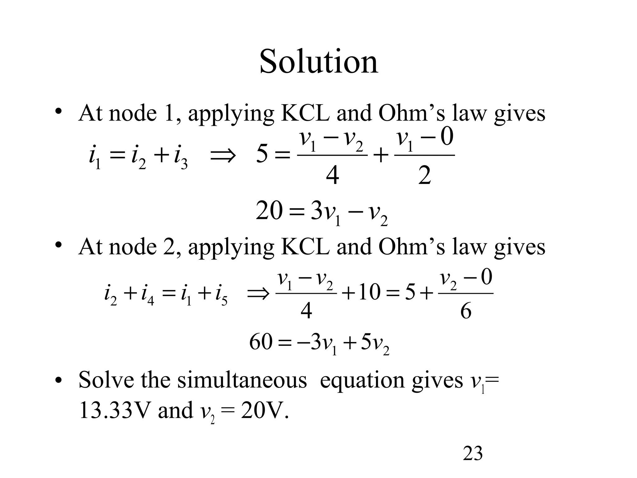
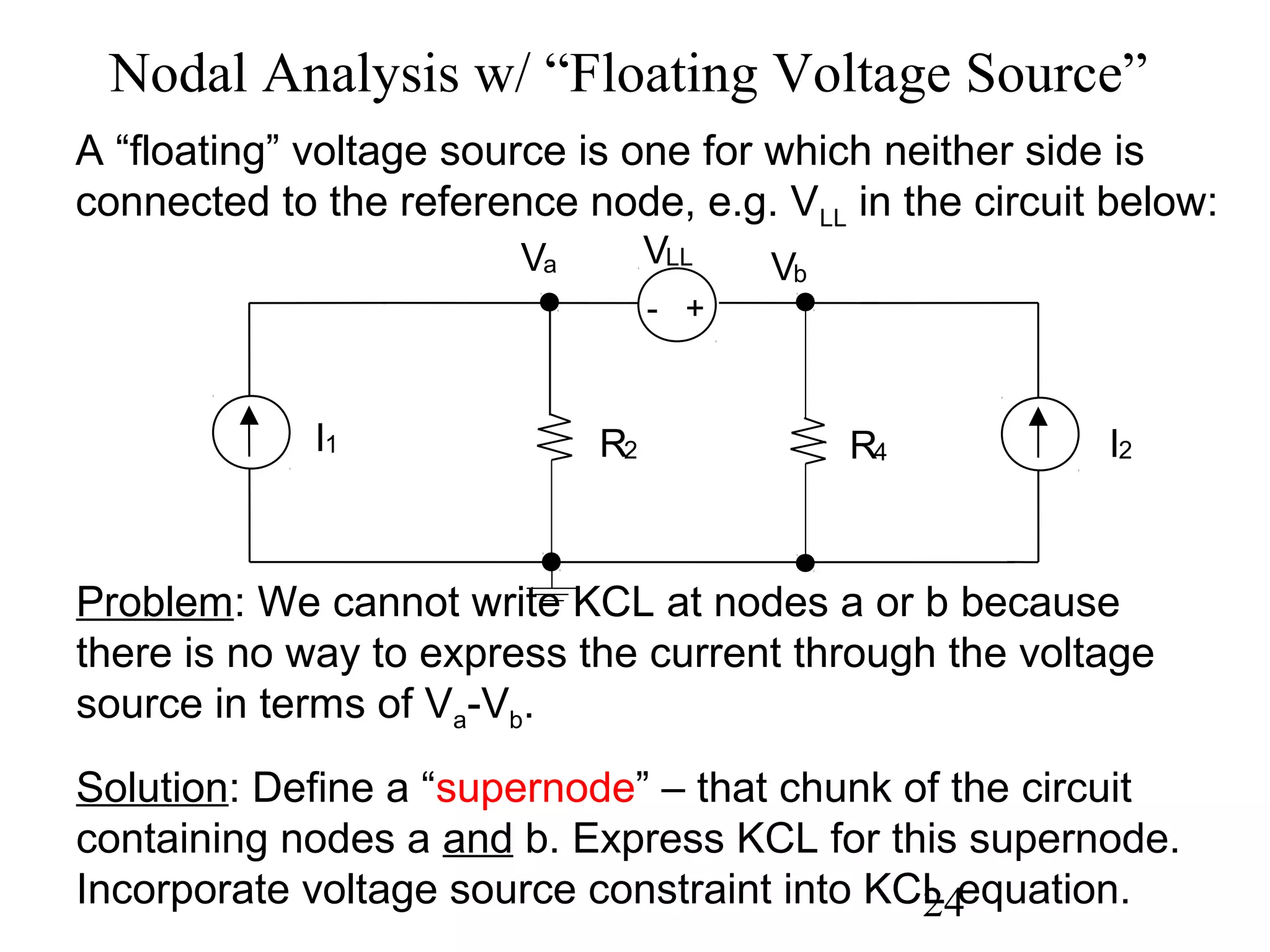
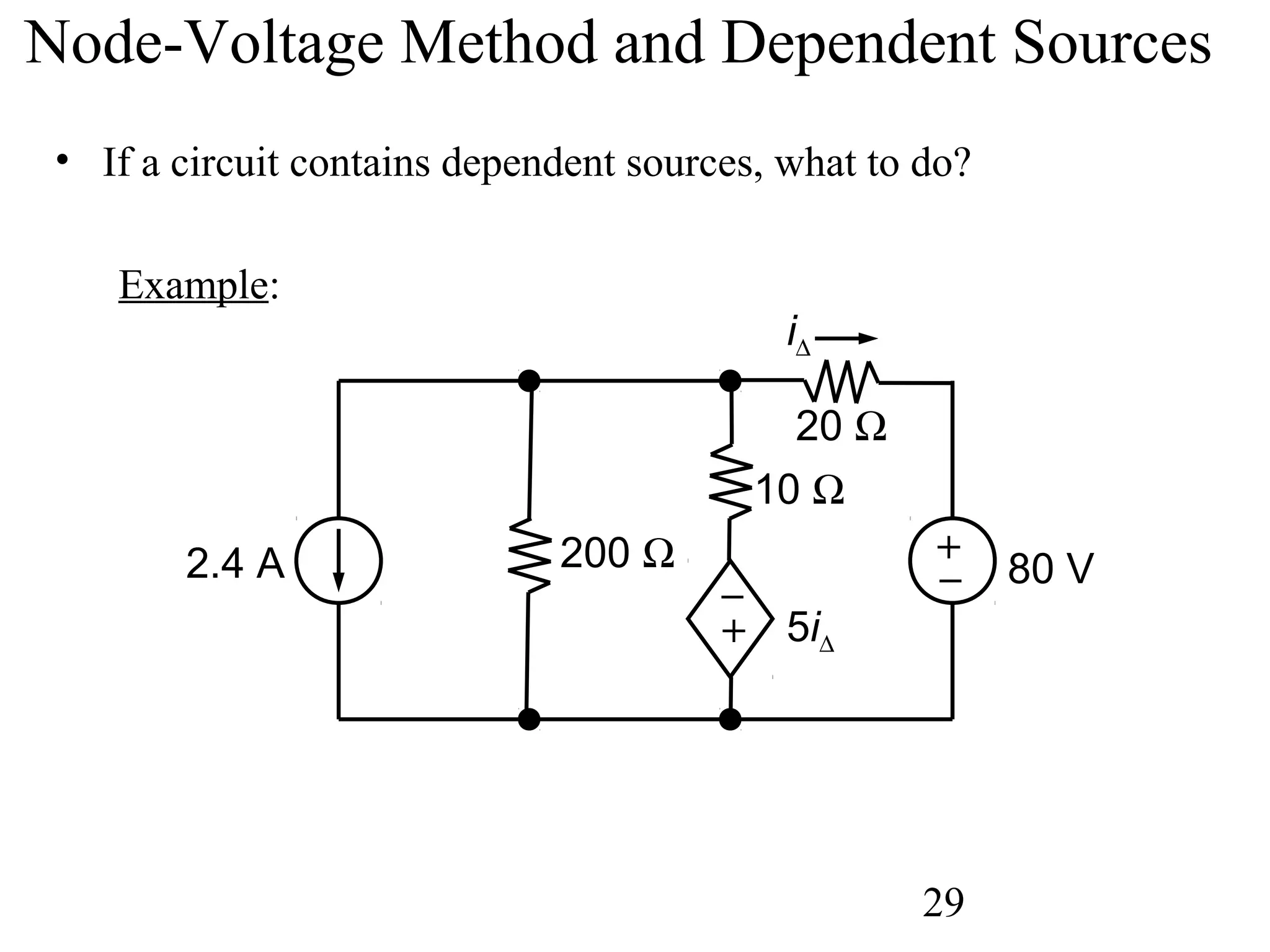
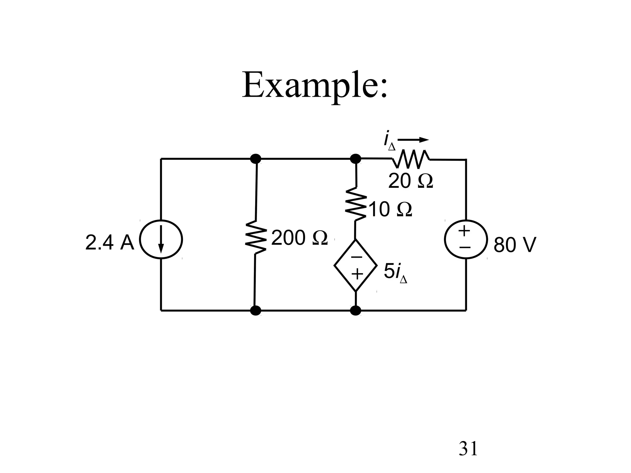
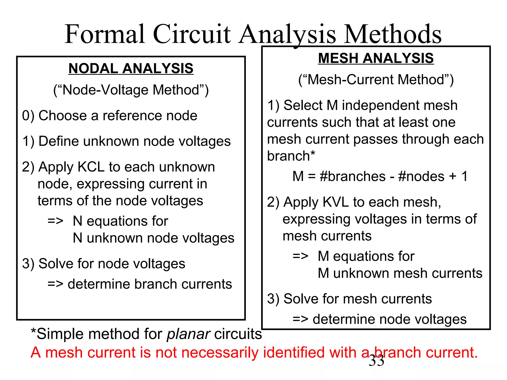
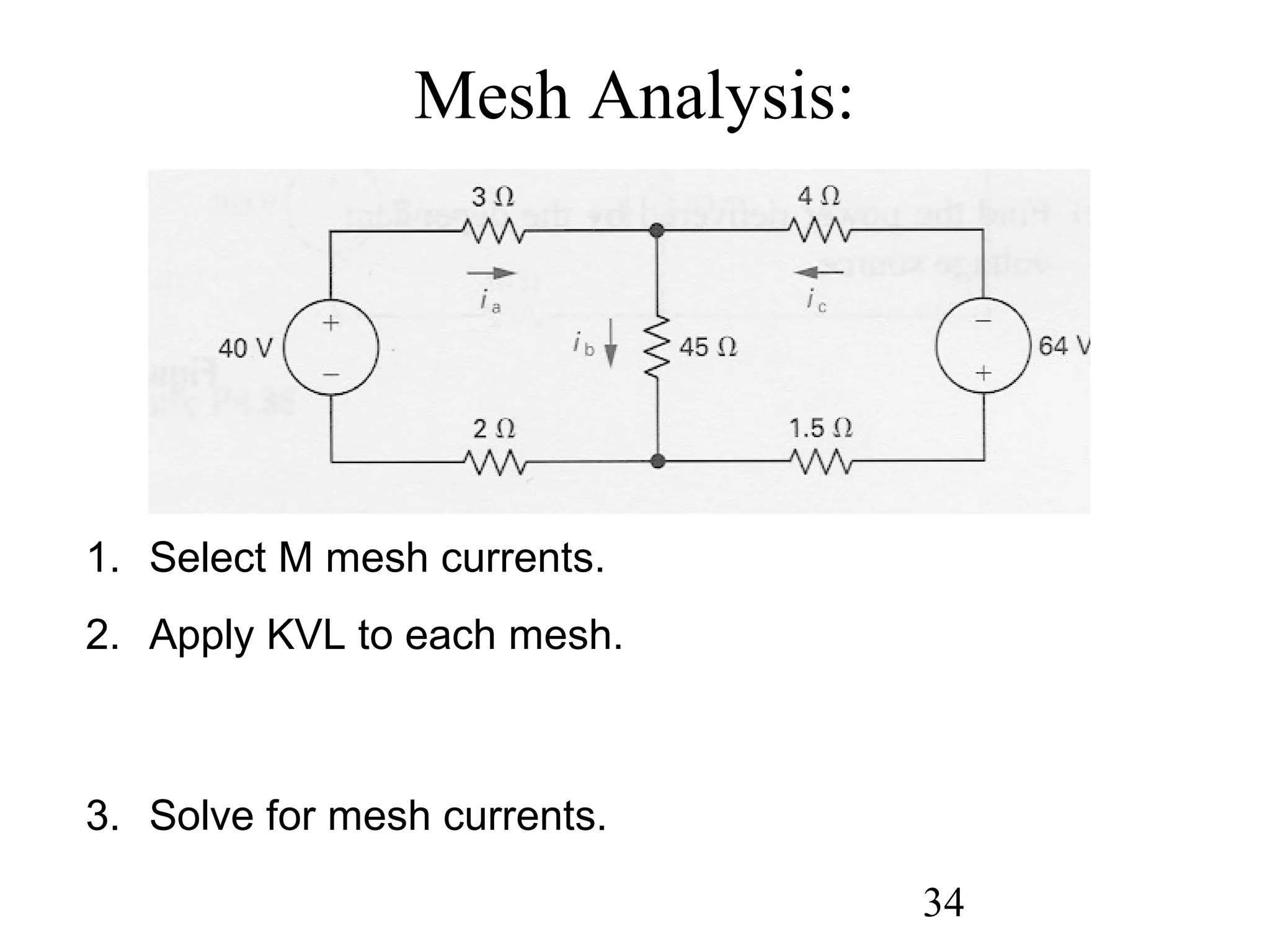
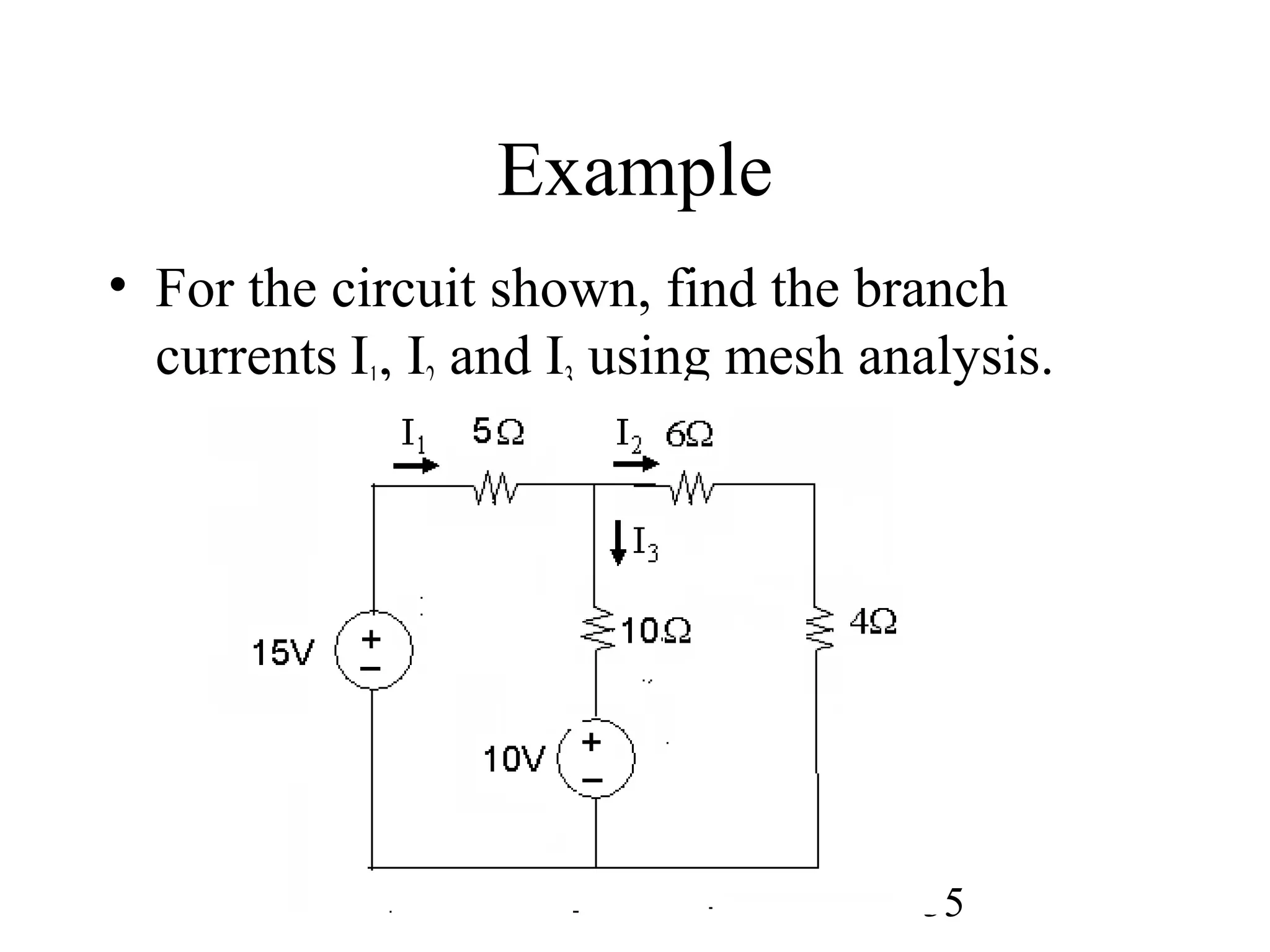
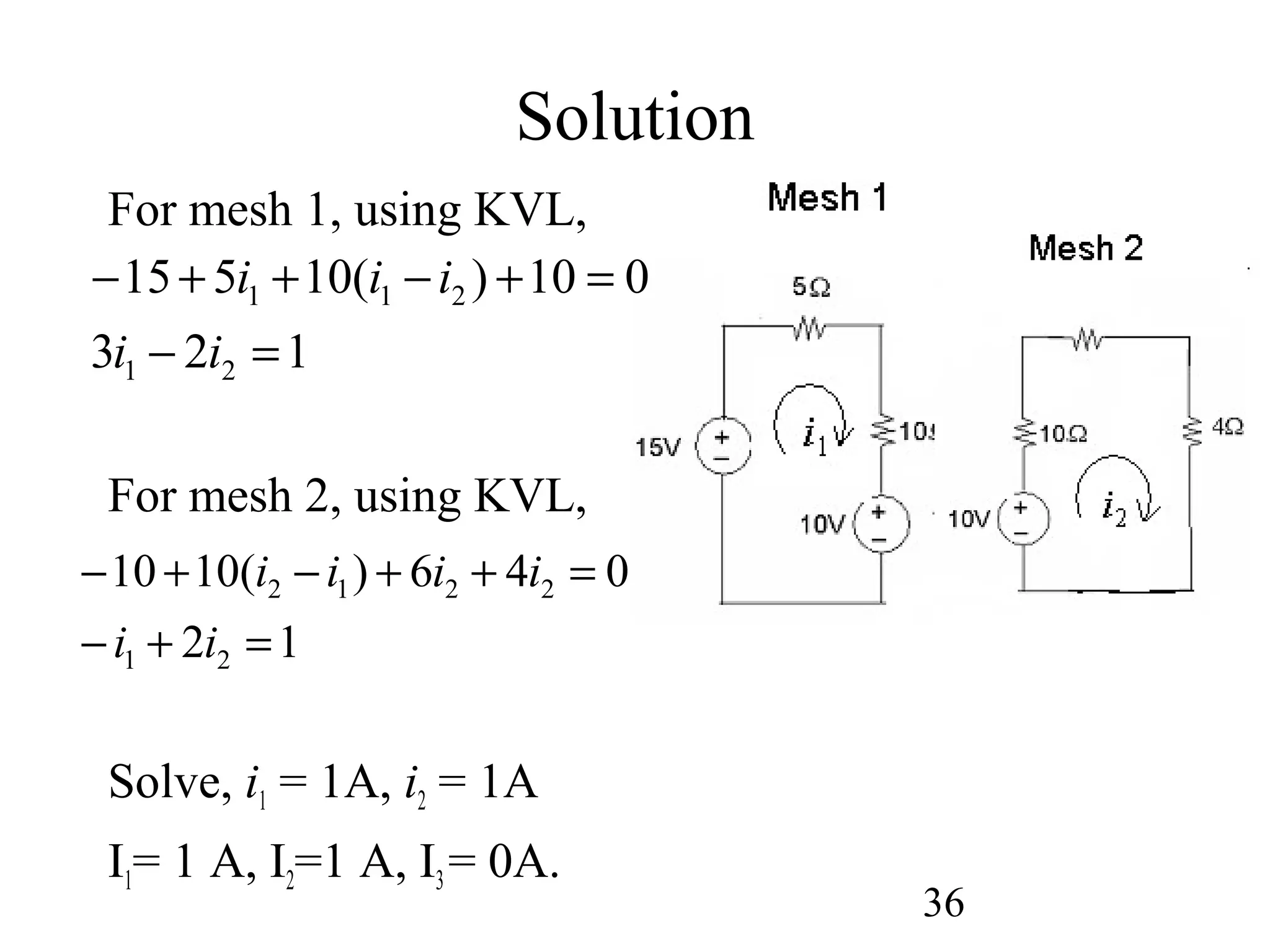
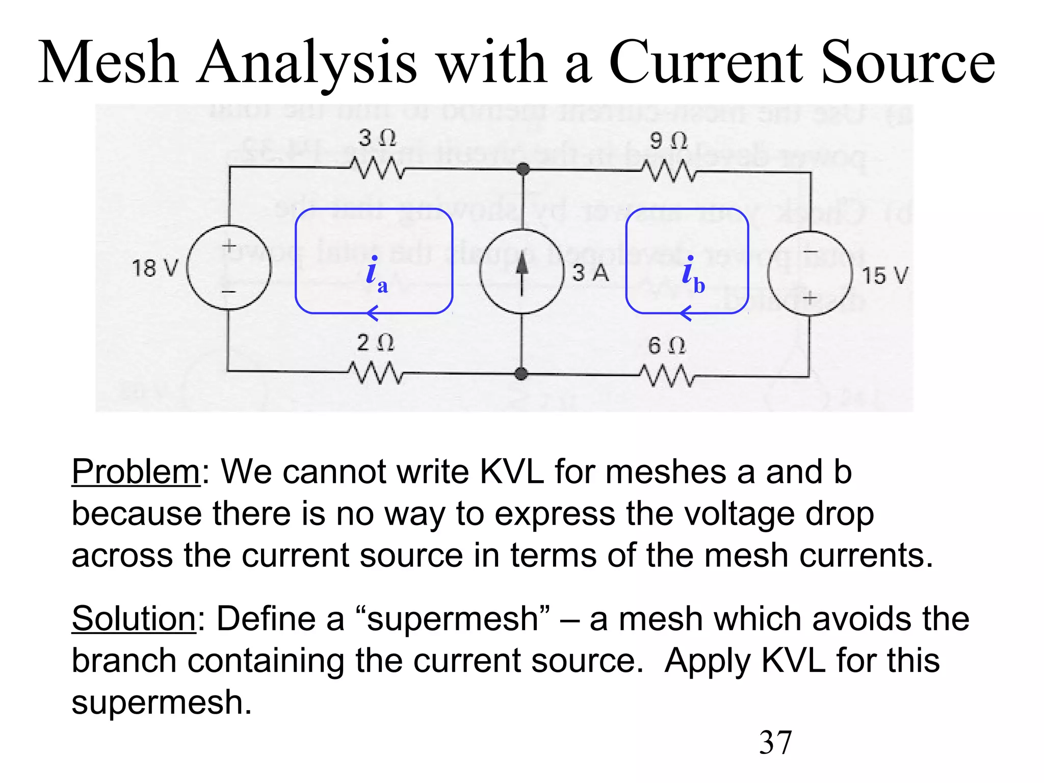
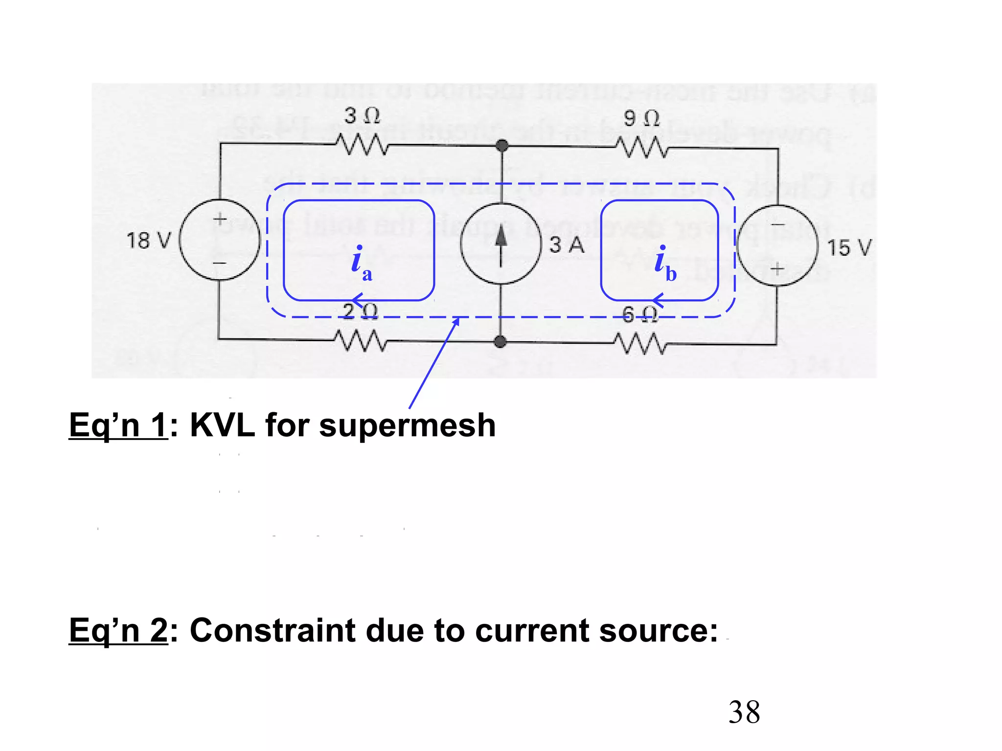
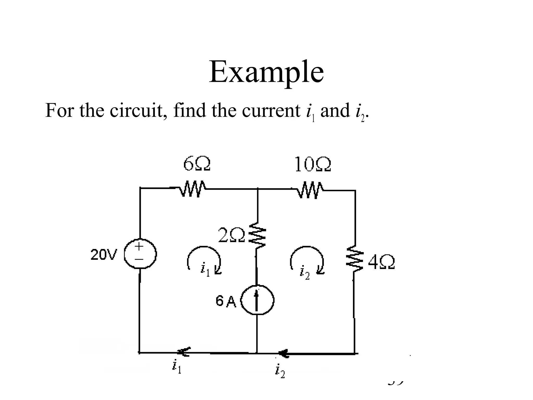
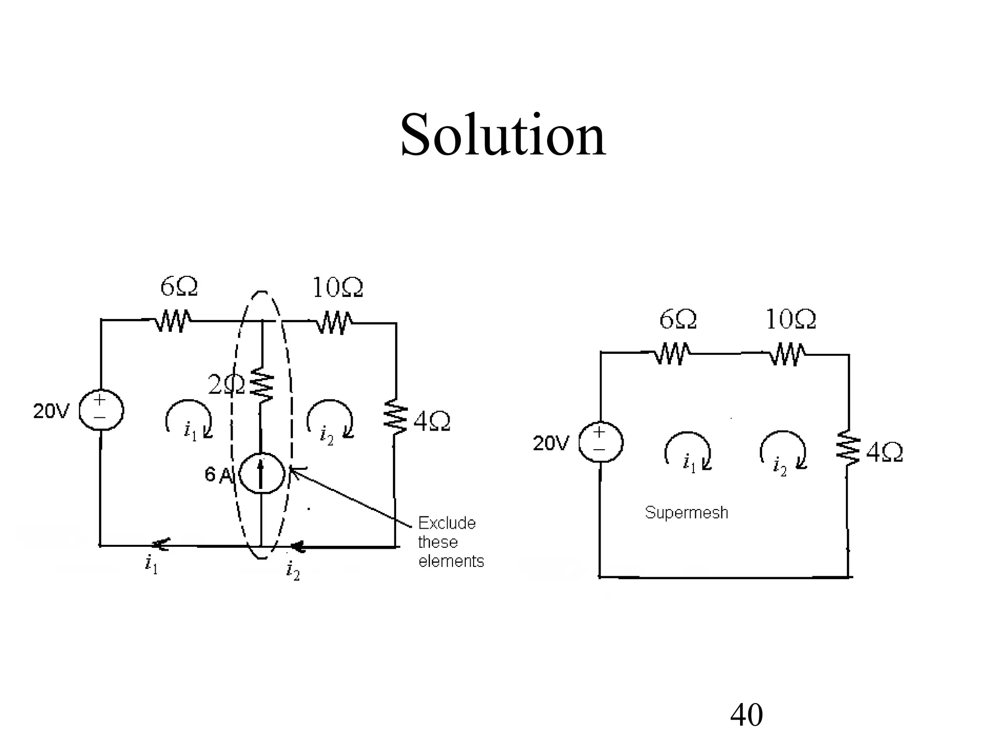
This document provides an overview of equivalent circuits and circuit analysis techniques including node-voltage analysis, mesh analysis, and dealing with dependent and independent sources. It defines equivalent circuits as circuits that can replace one another without changing the external behavior of the overall circuit. It also describes node-voltage and mesh analysis, specifying how to write equations for each method by applying Kirchhoff's laws. Techniques for handling dependent sources and circuits with no path to ground are discussed. Examples demonstrate transforming between delta-wye configurations and using the different analysis methods to solve for voltages and currents.