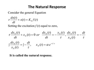
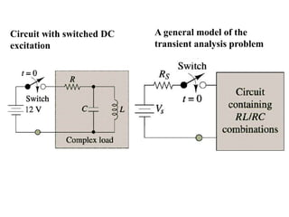
The document discusses transient analysis of first order differential equations that model circuits containing energy storage elements like capacitors and inductors. It explains that when the circuit conditions change, there will be a transient response before reaching the steady-state. The complete solution consists of the natural/homogeneous response and the particular/forced response. The natural response dies out over time, while the forced response depends on the external excitation. Circuits are solved using the time constant, which relates to how long it takes for the transient response to decay to the steady-state.


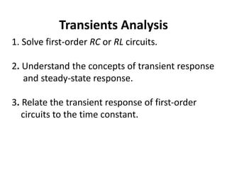
![The Complete Response
)(
)()(
/
/
xe
FKe
txtxx
t
S
t
FN
Consider the general Equation
The complete response is:
• the natural response +
• the forced response
)()(
)(
tfKtx
dt
tdx
s
Solve for ,
)()0(
)()0()0(
0
xx
xxtx
tfor
The Complete solution:
)()]()0([)( /
xexxtx t
/
)]()0([ t
exx
called transient response
)(x called steady state response](https://image.slidesharecdn.com/transientanalysis-170603060752/85/Transient-analysis-5-320.jpg)


![The Complete Response
)(
)()(
/
/
xe
FKe
txtxx
t
S
t
FN
Consider the general Equation
The complete response is:
• the natural response +
• the forced response
)()(
)(
tfKtx
dt
tdx
s
Solve for ,
)()0(
)()0()0(
0
xx
xxtx
tfor
The Complete solution:
)()]()0([)( /
xexxtx t
/
)]()0([ t
exx
called transient response
)(x called steady state response](https://image.slidesharecdn.com/transientanalysis-170603060752/85/Transient-analysis-26-320.jpg)


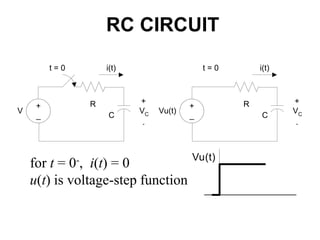
![RL CIRCUIT
Vu(t)
R
L
+
VL
-
i(t)
+
_
Vu(t)
ktRiV
R
L
sidesbothgIntegratin
dt
RiV
Ldi
V
dt
di
LRi
)ln(
,
0,
]ln)[ln(
ln,0)0(
/
/
tfore
R
V
R
V
i
ore
V
RiV
tVRiV
R
L
V
R
L
kthusi
LRt
LRt
where L/R is the time constant](https://image.slidesharecdn.com/transientanalysis-170603060752/85/Transient-analysis-34-320.jpg)