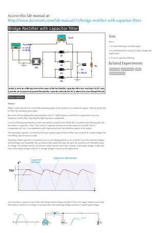
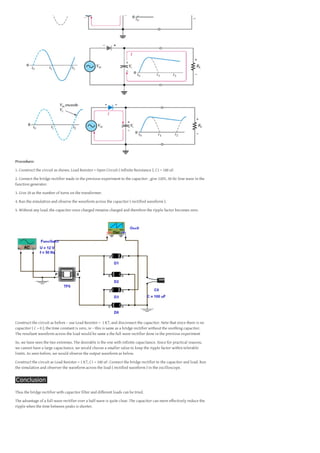
Access this lab-manual at:
http://www.docircuits.com/lab-manual/13/bridge-rectifier-with-capacitor-filter
Bridge Rectifier with capacitor filter
Aim
Aim is
1. To learn filtering of rectified signal
2. To understand the concept of ripple voltage and
ripple factor
3. To learn capacitive filtering

Related Experiments
CAPACITOR

RECTIFICATION

BRIDGE RECTIFIER

Description
Theory:
What is really desired is to convert the pulsating output of the rectifier to a constant DC supply. Thus we would like
to ‘filter’ the pulsating input signal.
We can do this by splitting the input waveform into AC ( high frequency ) and the DC components ( very low
frequency ) and by then ‘rejecting’ the high frequency components.
From our filtering experiments we have seen that the simplest kind of filter that can perform the filtering task just
described is a capacitor. Thus, if we connect a capacitor directly across the output of a rectifier, the AC
components will ‘see’ a low impedance path to ground and will not, therefore appear in the output.
The smoothing capacitor converts the full-wave rippled output of the rectifier into a smooth DC output voltage. The
smoothing capacitor acts as a tank.
Assuming a finite capacitor is connected, since a new charging pulse occurs every half cycle the capacitor charges
and discharges very frequently. We can observe that smaller the Vpp, the more the waveform will resemble a pure
dc voltage. The variable portion is known as ‘ripple’ and the value Vpp is known as the ripple voltage. Further the
ratio of the ripple voltage to the DC or average voltage is known as the ripple factor.

So we see that, a capacitor-input filter will charge and discharge such that it fills in the “gaps” between each peak.
This reduces variations of voltage. As we have seen, the remaining voltage variation is called ripple voltage.

DIODE
Procedure:
1. Construct the circuit as shown. Load Resistor = Open Circuit ( Infinite Resistance ), C1 = 100 uF.
2. Connect the bridge rectifier made in the previous experiment to the capacitor , give 220V, 50 Hz Sine wave in the
function generator.
3. Give 20 as the number of turns on the transformer.
4. Run the simulation and observe the waveform across the capacitor ( rectified waveform ).
5. Without any load, the capacitor once charged remains charged and therefore the ripple factor becomes zero.

Construct the circuit as before – use Load Resistor = 1 K?, and disconnect the capacitor. Note that since there is no
capacitor ( C = 0 ), the time constant is zero, ie – this is same as a bridge rectifier without the soothing capacitor.
The resultant waveform across the load would be same a the full wave rectifier done in the previous experiment
So, we have seen the two extremes. The desirable is the one with infinite capacitance. Since for practical reasons,
we cannot have a large capacitance, we would choose a smaller value to keep the ripple factor within tolerable
limits. As seen before, we would observe the output waveform as below.
Construct the circuit as Load Resistor = 1 K?, C1 = 100 uF. Connect the bridge rectifier to the capacitor and load. Run
the simulation and observer the waveform across the load ( rectified waveform ) in the oscilloscope.

Conclusion
Thus the bridge rectifier with capacitor filter and different loads can be tried.
The advantage of a full-wave rectifier over a half-wave is quite clear. The capacitor can more effectively reduce the
ripple when the time between peaks is shorter.

Bridge Rectifier with Capacitor filter

  • 1.
    Access this lab-manualat: http://www.docircuits.com/lab-manual/13/bridge-rectifier-with-capacitor-filter Bridge Rectifier with capacitor filter Aim Aim is 1. To learn filtering of rectified signal 2. To understand the concept of ripple voltage and ripple factor 3. To learn capacitive filtering Related Experiments CAPACITOR RECTIFICATION BRIDGE RECTIFIER Description Theory: What is really desired is to convert the pulsating output of the rectifier to a constant DC supply. Thus we would like to ‘filter’ the pulsating input signal. We can do this by splitting the input waveform into AC ( high frequency ) and the DC components ( very low frequency ) and by then ‘rejecting’ the high frequency components. From our filtering experiments we have seen that the simplest kind of filter that can perform the filtering task just described is a capacitor. Thus, if we connect a capacitor directly across the output of a rectifier, the AC components will ‘see’ a low impedance path to ground and will not, therefore appear in the output. The smoothing capacitor converts the full-wave rippled output of the rectifier into a smooth DC output voltage. The smoothing capacitor acts as a tank. Assuming a finite capacitor is connected, since a new charging pulse occurs every half cycle the capacitor charges and discharges very frequently. We can observe that smaller the Vpp, the more the waveform will resemble a pure dc voltage. The variable portion is known as ‘ripple’ and the value Vpp is known as the ripple voltage. Further the ratio of the ripple voltage to the DC or average voltage is known as the ripple factor. So we see that, a capacitor-input filter will charge and discharge such that it fills in the “gaps” between each peak. This reduces variations of voltage. As we have seen, the remaining voltage variation is called ripple voltage. DIODE
  • 2.
    Procedure: 1. Construct thecircuit as shown. Load Resistor = Open Circuit ( Infinite Resistance ), C1 = 100 uF. 2. Connect the bridge rectifier made in the previous experiment to the capacitor , give 220V, 50 Hz Sine wave in the function generator. 3. Give 20 as the number of turns on the transformer. 4. Run the simulation and observe the waveform across the capacitor ( rectified waveform ). 5. Without any load, the capacitor once charged remains charged and therefore the ripple factor becomes zero. Construct the circuit as before – use Load Resistor = 1 K?, and disconnect the capacitor. Note that since there is no capacitor ( C = 0 ), the time constant is zero, ie – this is same as a bridge rectifier without the soothing capacitor. The resultant waveform across the load would be same a the full wave rectifier done in the previous experiment So, we have seen the two extremes. The desirable is the one with infinite capacitance. Since for practical reasons, we cannot have a large capacitance, we would choose a smaller value to keep the ripple factor within tolerable limits. As seen before, we would observe the output waveform as below. Construct the circuit as Load Resistor = 1 K?, C1 = 100 uF. Connect the bridge rectifier to the capacitor and load. Run the simulation and observer the waveform across the load ( rectified waveform ) in the oscilloscope. Conclusion Thus the bridge rectifier with capacitor filter and different loads can be tried. The advantage of a full-wave rectifier over a half-wave is quite clear. The capacitor can more effectively reduce the ripple when the time between peaks is shorter.