Download to read offline
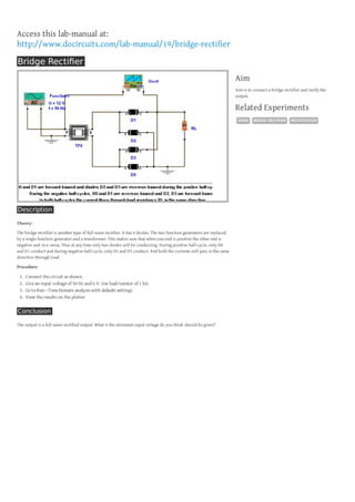

This document provides instructions for connecting a bridge rectifier circuit and verifying its output. It describes the theory behind how a bridge rectifier works using 4 diodes to produce a full-wave rectified output from an AC input signal. The procedure involves connecting the circuit as shown, applying a 6V 50Hz input, performing a time domain analysis with a 1kΩ load resistor, and viewing the full-wave rectified output on a plotter.